"
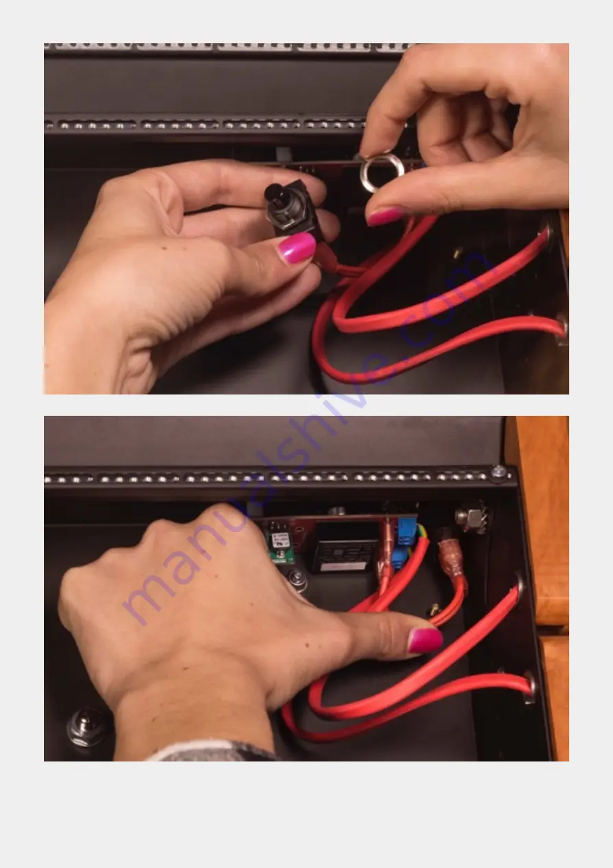
Put the button in place. Pay attention to do not force or disconnect the cables.
user manual rev 1 May 2016
Page
!
of
15
18
Page 1: ...SILTA made by SoundMachines for Frap Tools...
Page 2: ...1 SAFETY WARRANTY 2 2 WHAT IS SILTA 3 3 MOUNTING THE MODULE 3 4 EXTERNAL POWER BRICK 3 5 POWER UP 3 6 THE SILTA FLYING BUS 4 7 USB port 4 8 MOUNTING THE SILTA POWERKIT FOR UNO 4...
Page 3: ...n human injury property damage and or improper functioning of the device itself The device is designed for use only when safely and tightly mounted in a proper eurorack case made of non flammable mate...
Page 4: ...the address above for advice 2 WHAT IS SILTA SILTA is a clean regulated and protected power solution for eurorack systems The SILTA 6HP eurorack power module provides up to 1 25A 12V 1 25A 12V 1 5A 5...
Page 5: ...t circuits WARNING 500mA are enough in order to connect lamps or other equipment that require a powered USB port It is possible but not recommended to charge other devices like cell phones However be...
Page 6: ...Bend a bit as shown below the cables included in the kit to ease the insertion in the case Insert the cables from the inner row to the upper and lower rows user manual rev 1 May 2016 Page of 5 18...
Page 7: ...The cable comes out in the upper and lower row user manual rev 1 May 2016 Page of 6 18...
Page 8: ...port on the upper and lower row as shown below Pay attention to cable orientation red below yellow green above Insert the cables holding the SILTA boards on the blue or green connector DO NOT hold onl...
Page 9: ...g the SILTA board mainly with the blue or green connector After repeating the procedure for both upper and lower row repeat it for the middle row using the SILTA board with the smaller sheetmetal supp...
Page 10: ...Insert one of the eight 3mm spacers you unmounted in the beginning in the upper row and in the lower row user manual rev 1 May 2016 Page of 9 18...
Page 11: ...lower row as shown below pulling the red cable from the inner row as it is necessary Leave some cable in the upper and lower row as much as shown below Now insert the M3 teethed washer you unmounted...
Page 12: ...Now tight everything with the M3 wing nuts Do that for both upper and lower row and you ll get something similar to the picture below user manual rev 1 May 2016 Page of 11 18...
Page 13: ...Unmount the hex nut from the SILTA board of the inner row user manual rev 1 May 2016 Page of 12 18...
Page 14: ...Place the SILTA board in place in the inner row then tight the hex nut from the back as shown below user manual rev 1 May 2016 Page of 13 18...
Page 15: ...Unscrew the round nut from the I O button user manual rev 1 May 2016 Page of 14 18...
Page 16: ...Put the button in place Pay attention to do not force or disconnect the cables user manual rev 1 May 2016 Page of 15 18...
Page 17: ...Tight the round nut to the I O button again from the back of the UNO You may use a plier to ease the operation user manual rev 1 May 2016 Page of 16 18...
Page 18: ...nect the SILTA flying bus cable in the right position do not force it in the wrong one ALWAYS KEEP THE SILTA BOARD WITH YOUR HAND TO STRESS IT AS LESS AS POSSIBLE user manual rev 1 May 2016 Page of 17...
Page 19: ...uble check as soon as you turn it on that all the LEDs are lighted 2 LEDs in the upper and lower row for 12V and 12V and 3 LEDs in the inner row since it also have the 5V Turn it immediately off if on...