


www.soundskulptor.com
Document revision 1.2 – Last modification : 17/07/20
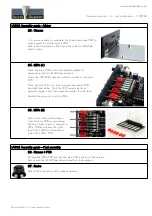
LA502 Assembly guide – Main PCB
10. Connector
Add CN1a. Solder one pin, check verticality then solder the other pins.
11. Opto-coupler
Bend the 2 wires that are widely spaced against the front.
The correct direction is given by the beveled side on the
left.
Insert, long lead into + hole and solder.
12. Trimmer potentiometers
Add P3 and P4 to P9. P3 is a different value from the others. Solder one pin, check verticality then
solder the other pins.
13. Non polarized electrolytic capacitors
Add C15, C3, C13.
These caps are not polarized and can be inserted in any direction.
14. Polarized electrolytic capacitors
Add C23, C24.
Warning
: The +lead must go into the +hole. Do not reverse (they may explode !)
15. Switches
Add SW1 to SW4. The position of the switches is critical for a good front-plate matching. They must sit
flat on the PCB. Press firmly the switch on the PCB and solder one of the front pins (housing). Check
verticality and horizontality. Then solder the other pins.
16. Input transformer
Insert and solder the input transformer.
17. Potentiometers P1 & P2
Place the bracket on the potentiometer bushing, and attach it with the lock washer and nut. Tighten.
Insert potentiometer and bracket into the PCB holes. Solder the central potentiometer pin. Now check
that the potentiometer shaft is perfectly parallel to the board.
Warning
: Do not only rely on the bracket being flat on the PCB, it sometimes need little visually made
adjustments to get a perfect position.
18. Output transformer
Insert and solder the output transformer.
19. IC's
Insert U1 to U6, U8 and U9 into their sockets. It is necessary to bend the pins slightly inward before
inserting.
Warning
: Make sure to insert the IC's in the correct direction which is identified by a notch.
Copyright ©2017 to Today SoundSkulptor


