Manual
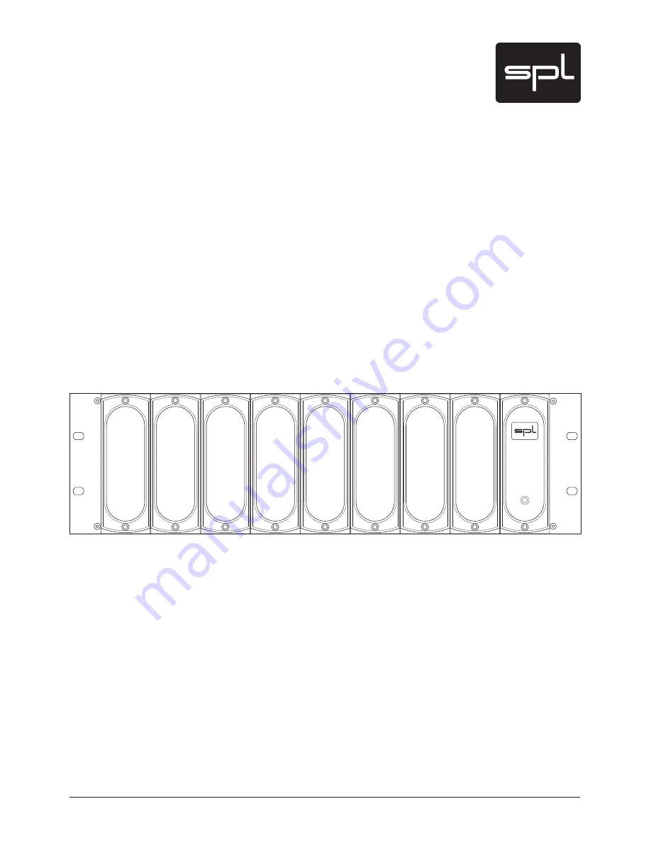
19"/3 U mounting frame for SPL RackPack modules
RackPack
Model 2710
3BDL
1BDL
.
"%&
*/(&3.
"/
:
108&3
Page 1: ...Manual 19 3U mounting frame for SPL RackPack modules RackPack Model 2710 3BDL 1BDL 3 108 3 ...
Page 2: ...essor Product RackPack Model 2710 Compliance Engineer Wolfgang Neumann Test Basis EN50081 1 1992 EN50082 1 1992 EN60065 1993 EN61000 3 3 1995 EN60065 2002 EN55013 2001 EN55020 2002 EN61000 3 2 2000 73 23 EWG 93 68 EWG We herewith declare that the construction of the RackPack Model 2710 is in compliance with the standards and regulations mentioned above Notes on environmental protection At the end ...
Page 3: ...Air Circulation Power Connection Signal Connections On And Off 8 Rear Panel Connections 9 Fitting Modules 10 Please Note Step 1 10 Step 2 and 3 11 Step 4 and 5 12 Link Cable Installation 13 External Power Supply 14 Description Placement Of The External Power Supply On And Off 14 Dimensions and Weight 15 Guarantee and Product Registration 15 Contents ...
Page 4: ... yourself to an electric shock In these cases SPL electronics GmbH denies any responsibility Electrical Power Run this machine ONLY from sources which can provide proper power at the prescribed rating When in doubt about a source contact your dealer or a professional electrician To be sure you have isolated the machine do so by disconnecting the power cord from your wall connection Be sure that th...
Page 5: ...cloth if necessary with an acid free cleaning oil Disconnect the machine from your power source before cleaning Warnings DO NOT PLACE THE MACHINE IN SUCH A WAY THAT IT MIGHT COME INTO CONTACT WITH OR SIT ON ANY FLUIDS AVOIDING SUCH CONTACT WILL AVOID HAZARDS FROM FIRE DANGEROUS ELECTRICAL SHOCK OR MACHINE DAMAGE DO NOT OPEN THE MACHINE THE LIGHTNING SYMBOL WITHIN A TRIANGLE WARNS YOU ABOUT UNINSUL...
Page 6: ...iking and while a continuous preamp quality is of immea surable value especially with multichannel recordings it is impressively economical as well now with the Preference Mic Pre module Further modules complete the RackPack system that includes the whole range of analogue peripheral equipment and allows for perfect integration into any live and studio environment From the passive equalizers Bass ...
Page 7: ...d so that you can easily reach it but there are other considerations Try not to place it near heat sources or in direct sunlight and avoid exposure to vibrations dust heat cold or moisture It should also be kept away from transformers motors power amplifiers and digital processors Always ensure sufficient air circulation by keeping a distance of 4 5 cm 2 inches to other units and to the sides of t...
Page 8: ...ith the multi pin connector on the other end is made to connect to the RackPack It is not possible to connect it incorrectly place the groove at the end of the plug on the spring at the socket on the RackPack and tighten the screw After connecting the external power supply to the RackPack and selecting the correct voltage on the external power supply connect the power supply to the wall socket and...
Page 9: ...3 3 4 0 53 4 0 0 0 5 0 1 6 5 0 108 3 4 165 108 3 065165 50 6 0 6 5 1035 5 0 5 108 3 03 50 6 0 6 5 03 48 5 0 108 3 FGPSF ZPV VTF UIF 3BDL1BDL NBLF TVSF UIBU UIJT WPMUBHF TFMFDUPS TXJUDI TFUUJOH SFGMFDUT UIF DPSSFDU MPDBM QPXFS MJOF WPMUBHF 7 QPTJUJPO 7 7 QPTJUJPO 7 5IF SFBS QBOFM MJGU TXJUDI FMJNJOBUFT IVN CZ TFQBSBUJOH UIF JOUFSOBM HSPVOE GSPN UIF VOJUµT IPVTJOH HSPVOE G IVN PDDVST QSFTT UIF TXJUD...
Page 10: ... the device and wait at least one minute before you disconnect the device from the external power supply Also disconnect any signal connec tions to other units and wait another five minutes to make sure no residual current is left before opening the RackPack This instruction explains how to fit a module into the third slot In this example modules have already been fitted into slot 1 and 2 You will...
Page 11: ... the two Phillips screws holding the cover panel of slot 3 on the rear Remove the cover panel As long as slot 3 is fitted with a module the cover will not be needed anymore You may want to store it for future use Step 3 Front View Unscrew the two Allen screws socket screws of slot 3 on the front of the RackPack frame with the Allen key and remove the silver decoration panel as well as the blank bl...
Page 12: ...f the front of the module Fix the panel and the front of the module by tightening the M4 screws into the threads of the housing see step 3 Step 5 Finally plug the multi pin connector of the ribbon cable that corresponds to the module s slot into the multi pin socket of the new module Make sure that the connection is safe and tight by plugging the connector completely into the socket IMPORTANT Only...
Page 13: ...xplain how to configure a module for master or slave mode All modules supporting LINK mode have a 10 pin socket on the top of their circuit board A flat ribbon cable with two 10 pin connectors is part of the module s scope of delivery Plug one of the two multi pin connectors of the ribbon cable into either one of the multi pin sockets of the modules to be connected Make sure that the connections a...
Page 14: ...ransients 48V phantom power is also processed using discrete low noise voltage regulators and fed directly to the microphone conductors through two resistors Placement Of The External Power Supply Do not place the RackPack on top of the external power supply or the power supply on top of the RackPack Place the external power supply on a level and stable surface only We recom mend a distance of at ...
Page 15: ...y from the date of purchase End users are supported in the two year guarantee through their distributor or dealer In such cases please contact your dealer for full guarantee conditions and service Direct SPL product support requires product registration Please fill out the guarantee card enclosed in the package legibly in printed letters and send it directly to SPL Or use the online registration f...
Page 16: ...RackPack Manual RackPack Model 2710 ...