17
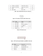
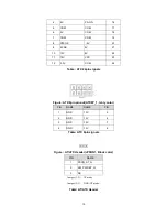
Figure : SATA Header pin-out(SATA1, SATA2, SATA3, SATA4, SATA5, SATA6, Black color)
PIN
NAME
1
GND
2
SATA_TX2_C_DP
3
SATA_TX2_C_DN
4
GND
5
SATA_RX2_C_DN
6
SATA_RX2_C_DP
7
GND
Table : SATA Header signals
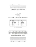
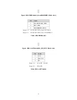
Figure : Panel power Header pin-out(J20, Black color)
PIN
NAME
Description
1
Key
No pin
2
3.3V
3.3V option (default)
3
12V
12V option
4
LCD_VCC
Send voltage to connector
5
Key
No pin
6
5V
5V option
Table : Panel power Header signal
Summary of Contents for sMB-Q370
Page 1: ...sMB Q370 embedded Motherboard Product Guide www sotm audio com Rev 1 1c...
Page 2: ......
Page 6: ...4 TABLE 2 SOtM sMB Q370 COMPONENTS SHOWN IN FIGURE 1...
Page 21: ...19 sMB Q370 embedded Motherboard BIOS Specification...
Page 78: ...76...
Page 79: ......
Page 80: ...www sotm audio com...


