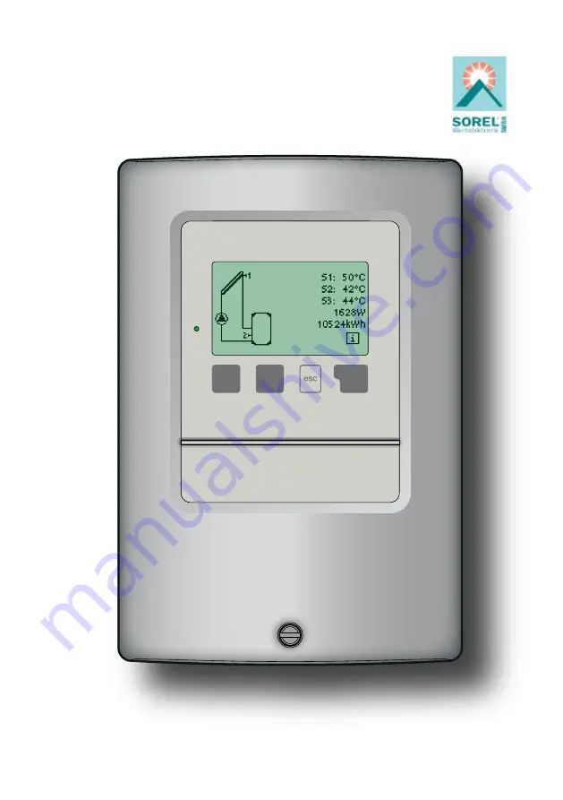
SOREL TDC 4
Temperature-Difference-Controller
Temperature Difference Controller TDC 4
Installation and operating instructions
Read carefully before installation, commissioning and operation
Page 1: ...SOREL TDC 4 Temperature Difference Controller Temperature Difference Controller TDC 4 Installation and operating instructions Read carefully before installation commissioning and operation...
Page 2: ...uage menu10 14 46 Malfunctions mainte nance 16 1 Error messages 16 2 Replacing the fuse 16 3 Maintenance 16 48 49 49 Installation 3 1 Wall installation 3 2 Electrical connection 3 3 Installing the sen...
Page 3: ...ns the regula tions of the local power utility the applicable DIN EN standards and the installation and operating instruction of the additional system components must also be observed The controller d...
Page 4: ...ginal spare parts and accessories Use of the device for other than its intended purpose Operation above or below the limit values listed in the specifications Force majeure Changes additions to or con...
Page 5: ...o moisture condensation permitted Other specifications and dimensions Housing design 2 part ABS plastic Installation methods Wall installation optionally panel installation Overall dimensions 163mm x...
Page 6: ...ng changes Resetting to previously selected values or factory settings A wide range of additional functions are available Description of controller 2 2 2 3 Scope of supply Temperature Difference Contr...
Page 7: ...complete The controller does not replace safety de vices under any circumstances Depending on the specific application additional system components and safety components may be mandatory such as chec...
Page 8: ...eing sure not to touch the elect ronics when doing so 4 Hold the lower part of the hou sing up to the selected position and mark the 3 mounting holes Make sure that the wall surface is as even as poss...
Page 9: ...g connected to the unit must not be stripped by more than 55mm and the cable jacket must reach into the housing just to the other side of the strain relief Relay R1 is only suitable for standard pumps...
Page 10: ...anger Caution Mains side 230VAC Caution Mains voltages 230VAC 50 60Hz Connection in the right hand terminal compartment Terminal Connection for L Mains phase conductor L N Mains neutral conductor N R1...
Page 11: ...to install the sensor in the return see also 12 7 heat metering The VFS has to be installed in the cor rect flow direction For additional advice regarding the sen sors and the VFS see 3 3 Installating...
Page 12: ...andard pumps minimum load 20VA Low voltage max 12VAC DC connec tion in the left hand terminal compart ment Terminal Connection for S1 Sensor 1 collector S2 Sensor 2 storage S3 Sensor 3 bypass flow S4...
Page 13: ...n the left hand terminal compart ment Terminal Connection for S1 Sensor 1 collector S2 Sensor 2 storage S3 Sensor 3 heating circuit return S4 Sensor 4 flow S5 VFS return C yellow S6 VFS flow l min whi...
Page 14: ...e to sensor 3 storage tank above Low voltage max 12VAC DC connec tion in the left hand terminal compart ment Terminal Connection for S1 Sensor 1 collector S2 Sensor 2 storage above S3 Sensor 3 storage...
Page 15: ...revent damage to the Vortex flow sensor it is strongly recommended to install the sensor in the return see also 12 7 heat metering The VFS has to be installed in the cor rect flow direction For additi...
Page 16: ...ollector with flow through sensor 3 Low voltage max 12VAC DC connec tion in the left hand terminal compart ment Terminal Connection for S1 Sensor 1 collector S2 Sensor 2 storage above S3 Sensor 3 coll...
Page 17: ...terminal compart ment Terminal Connection for S1 Sensor 1 collector S2 Sensor 2 storage above S3 Sensor 3 collector 2 S4 Sensor 4 flow S5 VFS return C yellow S6 VFS flow l min white VFS 5V DC brown ju...
Page 18: ...l connection continued Installation 3 3 Low voltage max 12VAC DC connec tion in the left hand terminal compart ment Terminal Connection for S1 Sensor 1 collector S2 Sensor 2 storage 1 S3 Sensor 3 stor...
Page 19: ...in the left hand terminal compart ment Terminal Connection for S1 Sensor 1 collector S2 Sensor 2 storage 1 S3 Sensor 3 storage 2 S4 Sensor 4 flow S5 VFS return C yellow S6 VFS flow l min white VFS 5V...
Page 20: ...ini mum load 20VA Low voltage max 12VAC DC connec tion in the left hand terminal compart ment Terminal Connection for S1 Sensor 1 collector S2 Sensor 2 storage 1 S3 Sensor 3 storage 2 S4 Sensor 4 flow...
Page 21: ...the left hand terminal compart ment Terminal Connection for S1 Sensor 1 collector S2 Sensor 2 pool S3 Sensor 3 flow primary S4 Sensor 4 flow secondary S5 VFS return C yellow S6 VFS flow l min white VF...
Page 22: ...e on charge to sensor 3 swimming pool Low voltage max 12VAC DC connec tion in the left hand terminal compart ment Terminal Connection for S1 Sensor 1 collector S2 Sensor 2 storage 1 S3 Sensor 3 pool S...
Page 23: ...ump to relay R2 Low voltage max 12VAC DC connec tion in the left hand terminal compart ment Terminal Connection for S1 Sensor 1 control S2 Sensor 2 reference S3 Sensor 3 thermostat S4 Sensor 4 flow he...
Page 24: ...o relay R2 Installation 3 3 3 2 Electrical connection continued Low voltage max 12VAC DC connec tion in the left hand terminal compart ment Terminal Connection for S1 Sensor 1 control S2 Sensor 2 ref...
Page 25: ...the PT1000 sensor should be inserted in an immersion sleeve mounted in the fluid The temperature sensor cables should be left inside the insulation for about 20 cm from the measuring point to prevent...
Page 26: ...to cancel an entry or to exit a menu If applicable there will be a request for confirmation as to whether the changes which have been made should be saved The function of each of the other three keys...
Page 27: ...there Current temperature values with explanations see 6 Function control of the system with operating hours etc see 7 Select graphics mode or overview mode see 8 Automatic mode manual mode or switch...
Page 28: ...aptations are necessary see 11 Menu 7 Special functions if additional changes are necessary see 12 through the necessary basic settings in the correct order and provides brief descriptions of each par...
Page 29: ...d of the measurement value then there may be a defective or incorrect temperature sensor Caution Measurement values menu 1 6 6 If the cables are too long or the sensors are not placed optimally the re...
Page 30: ...menu 2 4 This provides a clearly organised display of the data listed under 7 1 7 3 as a bar graph Various time ranges are available for comparison The two left hand keys can be used to page through t...
Page 31: ...by pressing esc or selecting Exit display mode 8 1 Graphics menu 3 1 In graphics mode the selected hydraulic systems are depicted with the mea sured temperatures and operating states of the connected...
Page 32: ...tion control 9 2 Manual menu 4 2 9 3 Off menu 4 3 When the operating mode Off is activated all controller functions are switched off This can lead for example to overheating on the solar collector or...
Page 33: ...itches the associated pump and or valve on If the temperature at sensor 1 drops below this value by 5 C then the pump and or the valve are switched off again Setting range from 0 C to 99 C default set...
Page 34: ...menu 5 x switch off temperature at sensor 3 If this value is exceeded at sensor 3 and the other conditions are also met then the controller switches the associated pump and or valve off If sensor 3 f...
Page 35: ...has risen to Tsetpoint S3 plus the hysteresis If the temperature at sensor 3 exceeds this value and a negative value is set under Hysteresis then relay R2 switches on as a heat dissipation function Th...
Page 36: ...t will soon enable charging in the higher priority storage tank If the conditions for charging the higher priority storage tank or for continued interruption are not met then the charging of the lower...
Page 37: ...S1 S2 R1 S1 S2 R1 T R2 S2 S3 R2 S3 S2 R2 S1 S3 R2 S2 S3 R2 S2 S3 R2 Tsetpoint S3 S3 R2 S3 R2 hysteresis S3 R2 S3 R2 Priority S2 o S3 R1 R2 S2 o S3 R1 R2 S2 o S3 R1 R2 S2 o S3 R1 R2 T Priority S2 o S3...
Page 38: ...e R2 daily weekly off default setting daily 11 2 Frost protection menus 6 2 6 2 1 6 2 2 A two stage frost protection function can be activated In stage 1 the controller switches the pump on for 1 minu...
Page 39: ...red The red light flashes and the corresponding warning appears in the display Col alarm setting range Off 60 C to 300 C default setting Off SPF variant V1 If the value SPF T on is exceeded at the col...
Page 40: ...ed off at delivery This function is only relevant for storage tanks where sensor 2 is installed Whenever heating up has been carried out with the anti Legionella function switched on an information me...
Page 41: ...tion can lead to unpredictable errors For analysis of the system data it is essential for the time to be set accurately on the controller Please note that the clock does not continue to run if the mai...
Page 42: ...ressing the esc key takes you back to the previous value so you can look at the selected setting again or adjust it if desired Pressing the esc more than once takes you back to the selection mode thus...
Page 43: ...asurement values In particular follow the instructions from the collector manufacturer Special functions menu 7 12 12 12 7 Heat quantity menus 7 7 7 7 1 7 7 5 In this menu the type and percentage of t...
Page 44: ...e pump is switched off Variant V2 After the purging time the controller switches to the set min speed If the temperature difference T between the reference sensors collector and storage tank is greate...
Page 45: ...ed menu 7 9 5 12 9 6 Setpoint menu 7 9 6 The maximum speed of the pump at relay R1 is specified here During the setting the pump runs at the specified speed and the flow rate can be determined Setting...
Page 46: ...neces sary 1 Measurement values 2 Analysis 3 Display mode 7 2 Time date 8 Menu lock 9 Service values To lock the other menus select Menu lock on To enable the menus again select Menu lock off Setting...
Page 47: ...he menu 9 Service values can be used for remote diagnosis by a specialist or the manufacturer in the event of an error etc Caution Enter the values at the time when the error occurs e g in the table T...
Page 48: ...alist Means that either the sensor the sensor input at the controller or the connecting cable is was defective Resistance table on page 5 Means that the collector has fallen fell below the temperature...
Page 49: ...re working on the unit switch off the power supply and secure it against being switched on again Check for the absence of power Danger Danger Only use the supplied spare fuse or a fuse of the same des...
Page 50: ...l method for remote diagnosis Write the service values down see 15 at the time that the suspected malfunction occurs Send the service value table by fax or e mail with a brief description of the error...
Page 51: ...ump is active In the universal programs 14 15 the times refer to relay R1 To protect against loss of data record any analyses and data that are particularly important to you see 7 at regular intervals...
Page 52: ...created with the greatest possible care the possibility of incorrect or incomplete information cannot be ex cluded Subject as a basic principle to errors and technical changes Notes SOREL GmbH Mikroel...