


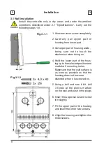


11
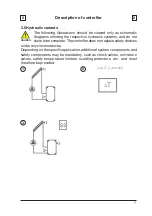
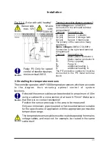
3.3 Installing the temperature sensors
The temperature sensor cables must be routed separately from mains
voltage cables, and must not, for example, be routed in the same
cable duct!
Caution
The controller operates with Pt1000 temperature sensors which are accurate
to the degree, thus ensuring optimal control of system
functions.
Caution
If desired the sensor cables can be extended to a maximum of 30m
using a cable with a cross-section of at least 0.75mm². Make sure
that there is no contact resistance!
Position the sensor precisely in the area to be measured!
Only use immersion, pipe-mounted or flat-mounted sensor suitable
for the specific area of application with the appropriate permissible
temperature range.
Installation
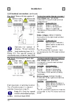
Terminal connection diagram, program 3
Fig. 3.2.4 „Solar with add. heating“
Low voltage
max. 12VAC/DC
connection in the left-hand terminal
compartment!
Terminal:
Connection for:
S1 (2x)
Sensor 1 collector
S2 (2x)
Sensor 2 storage tank
S3 (2x)
Sensor 3 thermostat
The polarity of the sensors is freely
selectable.
Relay R1: Only for speed
control of standard pumps,
minimum load 20VA
Mains voltages
230VAC 50-60Hz
Connection in the right-hand terminal
compartment!
Terminal:
Connection for:
L
Mains phase conductor L
N
Mains neutral conductor N
R1
Pump L (speed)
N
Pump N
R2
additional heating L
N
additional heating N
The PE protective conductor must be
connected to the PE metal terminal
block!
Sensor side
max. 12V
Danger
Caution
Mains
side
230VAC
Caution
Summary of Contents for TDC 2
Page 35: ...35 Notes...


