Read carefully before installation, commissioning and operation
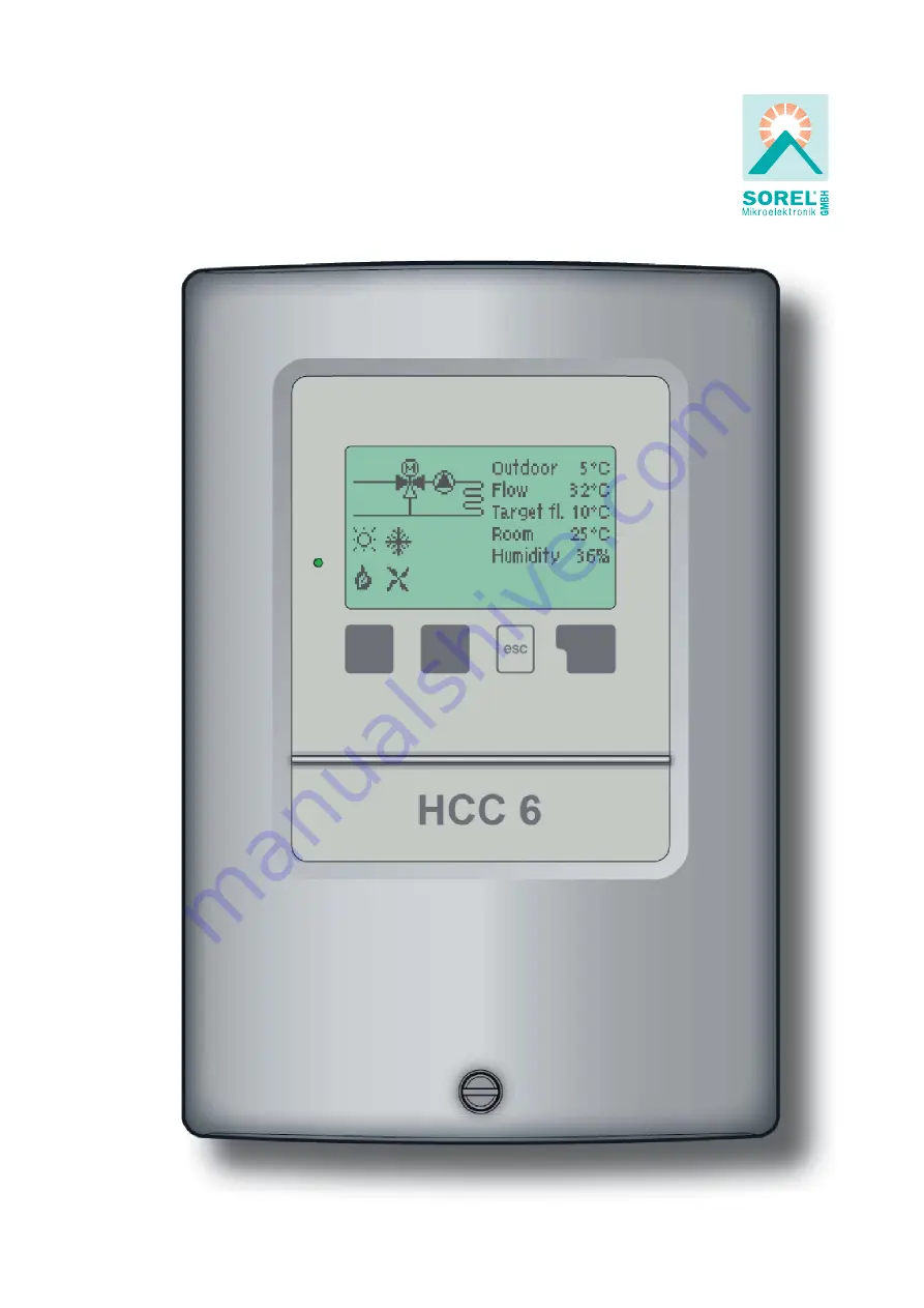
Heating-Controller HCC 6
Installation and operating instructions
Weather controlled heat circuit regulator
carefully before iinsttallllattiion commiissiioniing and operation
Page 1: ...nstallation commissioning and operation Heating Controller HCC 6 Installation and operating instructions Weather controlled heat circuit regulator carefully before i inst tal ll lat ti ion commi issi...
Page 2: ...19 4 5 Heat circuit reference 19 4 6 14 day reference 19 5 Settings 20 5 1 Heat circuit 20 5 1 1 Su Wi Day 20 5 1 2 Su Wi night 20 5 1 3 Curve 21 5 1 4 Day correction 22 5 1 5 Night correction 22 5 1...
Page 3: ...ons the regulations of the lo cal power utility the applicable DIN EN standards and the installation and operating instruction of the additional system components must also be observed The controller...
Page 4: ...d accessories Use of the device for other than its intended purpose Operation above or below the limit values listed in the specifications Force majeure Changes additions to or conversion of the unit...
Page 5: ...storage 0 C 60 C Air humidity for controller operation max 85 humidity at 25 C for transport storage no moisture condensation permitted Other specifications and dimensions Housing design 2 part ABS p...
Page 6: ...ons Menu block can be activated to prevent unintentional setting changes Resetting to previously selected values or factory settings various additional functions are or will be available e g 0 10V con...
Page 7: ...ive hydraulic systems and do not claim to be complete The controller does not replace safety devices under any circumstances Depending on the specific application additional system components and safe...
Page 8: ...the 3 mounting holes Make sure that the wall surface is as even as possible so that the housing does not become distorted when it is screwed on 5 Using a drill and size 6 bit drill 3 holes at the poin...
Page 9: ...side of the unit and mains voltage cables only into the right hand side The cables being connected to the unit must not be stripped by more than 55mm and the cable jacket must reach into the housing j...
Page 10: ...ptimal control of system functions Caution Caution If needed the sensor cables can be extended to a maximum of 30m using a cable with a cross section of at least 0 75mm Make sure that there is no cont...
Page 11: ...rminal Connection for N Jumper terminal blockN L Mains phase conductor L R1 Heat circuit pump R2 Mixer open R3 Mixer close R4 Cooling Heating mode R5 add heating cooling R5I add heating cooling The PE...
Page 12: ...uld be saved The function of each of the other three keys 4 is shown in the display line directly above the keys the right hand key is generally has a confirmation and selec tion function Examples of...
Page 13: ...to test the switch outputs with the consumers connected and to check the sensor values for plausibility Then switch on automatic mode Caution Observe the explanations for the individual parameters on...
Page 14: ...ges at critical points For diagnosis in the event of an error Selection of the menu language 1 Measurements 2 Statistics 3 Times 4 Operating mode 5 HC settings 6 Cool settings 7 Protections 8 Special...
Page 15: ...y instead of the measurement value then there may be a defective or incorrect temperature sensor If the cables are too long or the sensors are not placed optimally the result may be small deviations i...
Page 16: ...heating 2 6 Error messages 2 7 Reset clear Flow temperature for the present day In the graphical overview the characteristics of outdoor and flow temperature for the present day is shown from 0 24h Th...
Page 17: ...rately on the controller Please note that the clock continues to run for about 24 hours if the mains volt age is interrupted and after that has to be reset Caution This menu can be used to select a ti...
Page 18: ...4 6 14 day reference After 14 days the reference temperature of the 14th day is used until the operating mode is changed Off Heating circuit is switched off except Frost protection Heating can also b...
Page 19: ...rrect assignment 4 4 Manual The operating mode Manual may only be used by specialists for brief function tests e g during commissioning Danger If operating mode Reference value is selected in 4 1 Heat...
Page 20: ...matically switches the heating circuit off Summer mode If the outdoor temperature drops below this value the heating circuit is switched on again Winter mode Settings range from 0 C to 30 C Default 18...
Page 21: ...adjusting the curve the steepness of the slope and the cal culated reference flow temperature for 12 C outdoor temperature is displayed Settings range Characteristic curve simple or split Default simp...
Page 22: ...urve The night correction produces a parallel translation of the heating characteristic during the nighttime operating hours If a negative value is set for the night correction the ref erence flow tem...
Page 23: ...and cooling To prevent excessive oscillation when additional heating or cooling start the corre sponging relay is switched on up to 5 minutes after the switch on conditions are met Settings range 0 to...
Page 24: ...rrection can be used to shift the calculated dew point by up to 10 C Example Condesation occurs with the standard value The dew point room tem perature should be higher Example Condensation can be ign...
Page 25: ...oling mode This is the lower limit of the flow reference temperature for cooling Einstellbereich 5 C bis 20 C Voreinstellung 10 C 5 2 6 Min flow cool Maximum flow temperature in cooling mode This is t...
Page 26: ...umidity sensor S5 is shortcircuited in cooling mode A C cooling function can operate with a manually fixed humidity value Einstellbereich 50 100 Voreinstellung 70 Danger Manual humidity can lead to co...
Page 27: ...e operating modes Reference value and 14 days reference Caution The RC22 is used to set the 3 operating modes Heating Off and Cool ing Also the dial is used to influence the reference flow temperature...
Page 28: ...ler switches the heat circuit back on with the reference temperature set in menu 7 3 min flow temperature As soon as the outdoor temperature exceeds 1 C the heat circuit is switched off again Frost pr...
Page 29: ...errors Starting the commissioning help guides you in the correct order through the basic set tings necessary for commissioning and provides brief descriptions of each parameter in the display Pressing...
Page 30: ...closing for the time span set here then the temperature is measured to control the flow temperature Settings range 0 5 sec to 3 sec Default 2 sec 7 5 2 Pause Factor The calculated pause time of the mi...
Page 31: ...menu lock The menus listed below remain completely accessible despite the menu lock being activated and can be used to make adjustments if necessary 1 Measurement values 2 Statistics 3 Times 8 Menu l...
Page 32: ...remote diagnosis by a specialist or the manufacturer in the event of an error etc Caution The menu can be closed at any time by pressing esc Service values 9 Service values Enter the values at the ti...
Page 33: ...the language for the menu guidance This is que riedautomaticallyduringinitialcommissioning The choice of languages may differ however depending on the device design Language selectionisnotavailableine...
Page 34: ...r info symbol Notes for the specialist Means that either the sensor the sensor input at the controller or the connecting cable is was defective Resistance table on page 5 Means that the controller was...
Page 35: ...a specialist Before working on the unit switch off the power supply and secure it against being switched on again Check for the absence of power Danger Only use the supplied spare fuse or a fuse of t...
Page 36: ...or e mail with a brief description of the error to the specialist To protect against loss of data record any statistics and data that are particularly important to you see 2 at regular intervals Usef...