


– 12 –
WA1
RM-Y1108
PR
OGRAMME LABELS
This option
allows you to name a channel
us
ing
up
to
five characters
(letters or numbers).
To do
th
is
:
1
Once you
hav
e entered th
e "Set Up"
menu as
it is explained in the
prev
ious page
and
af
ter
selecting
this
option,
pre
ss
OK
, then pre
ss
v
or
V
to select the
programme number with
th
e channel
you wish to name.
Next
press
OK
.
2
Wi
th the
fi
rst
el
em
en
t of the
Label
column h
ighlighted, press
OK
and
v
,
V
,
B
or
b
to sele
ct
t
he le
tte
r, ne
xt
pre
ss
OK
.
When
you h
ave finished
, press
v
,
V
,
B
or
b
t
o select
the word
“
En
d
”
on
the scr
een and f
inally
press
OK
to
turn off
the menu from the screen.
To cor
rec
t a le
tte
r, sel
ect
"
%
" on the
screen to
go back and press
OK
.
Fo
r
a
blank, select "
"
on the screen and
press
OK
.
AV PRESET
This option
allows you to:
a)
Designate a name to
th
e external equipment you have
connected
to the
in
put so
ckets
of the TV
set.
To do
th
is
:
1
Once you have entered the
"Set
Up" menu as it is exp
lained in
the previous page and af
ter
selectin
g
this option,
press
OK
, the
n
pr
ess
v
or
V
to select
the inp
ut sour
ce
you wish to name:
AV1
and
AV
2
for the
rear
Scarts
and
AV3
for
side connect
ors.
Next
press
OK
twi
ce
.
2
A
la
bel
a
utom
ati
ca
ll
y a
ppea
rs i
n t
he
la
bel
c
olum
n:
a)
If yo
u want to
use
one
of the
predefined labels,
press
v
or
V
to select
the desi
red
label an
d fin
ally press
OK
.
The t
ot
al pre
defi
ned la
bel
s are:
VIDEO, DVD, CABLE, GA
ME
,
CAM
(camcorder)
or
SA
T
(sa
tel
li
te).
b)
If
you
want
to
set a di
fferent label,
select
Edit
and press
OK
. T
hen
, wi
th
the
first
el
em
ent
hig
hligh
ted
, p
ress
v
,
V
,
B
or
b
t
o se
le
ct
t
he le
tt
er,
next
pr
ess
OK
. Wh
en you have fin
ished, press
v
,
V
,
B
or
b
to
select
the wor
d
“
End
”
on the screen
and finally
press
OK
to turn off the
menu from
the screen.
To cor
rec
t the le
tt
er,
se
lec
t "
%
" on
the screen to g
o back
an
d press
OK
.
Fo
r
a
blank,
select "
" on
the screen an
d
press
OK
.
b)
C
hange the
inpu
t sound
level o
f the
optional equipment connected.
To do
th
is
:
Once you
have
entered
the
"Set
Up" menu
as
it is
explained
in
the p
revious page
and
after selectin
g this op
tion
press
OK
, the
n
pr
ess
v
or
V
to select
th
e input source you want to alter
the input
sound
level:
AV1
and
AV2
for the
rear Scarts
and
AV
3
for side co
nnectors.
Next press
twice
b
to hig
hligh
t
th
e
Sou
nd Offset
column.
Finally press
OK
and
v
or
V
to alter
the inpu
t
soun
d
level between -9 and +9
.
The Manual Programme Preset Menu
The
“Manual Programme
Pr
eset
” opti
on in the
"Set
Up" menu
allows y
ou to manually tune
individual channels.
To do
th
is:
Pres
s the
MEN
U
bu
tton
and press
v
thre
e tim
es
to
sele
ct
, t
hen
press
OK
to enter the
"Set
Up" menu.
Next, p
ress
v
or
V
to
se
lec
t
"Manual Pr
ogramme
Preset" and press
OK
.
Finally, r
ead below
how to operate
into each
option.
The
Manu
al Programme Pres
et option allows
you to:
a)
Preset chann
els
or the
VCR channel one b
y
one to the
programme
order of
your
choice.
To do this:
1
Once you have
entered
th
e
“Set Up
”m
enu as it is
explained on
page
23 and
after
selecting
the "Manual
Pr
ogramme
Preset" option, press
OK
. Next
with
Program
me
option
hi
ghlighted press
OK
.
Pres
s
v
or
V
to select
which p
rogramme nu
mber yo
u want
to
preset the
channel
on (f
or VCR, select
programme numb
er
“0
”). Th
en press
B
.
2
The f
ollo
wing o
ptio
n is
only
available
depending on
th
e
country y
ou have selected
in
th
e
“Coun
try
”
menu
.
Afte
r se
le
ct
ing th
e
Sys
tem
option, press
OK
. Then
press
v
or
V
to select t
he TV Bro
adcast system
(
B/G
for
western European
cou
ntries,
D/K
for
easter
n European
coun
tries,
L
fo
r France or
I
for
United
Kingdo
m).
The
n pr
ess
B
.
3
Af
ter
sel
ec
ting
th
e
C
h
annel
option, pr
ess
OK
. Next
press
v
or
V
t
o select
the chan
nel
tun
ing
("
C
" for
terrestr
ial
chan
nels or "
S
" for
cab
le channels). Th
en press
the number buttons
to
enter
di
rectly
the channel
numb
er of
the TV Broadcast
or
th
e channel
of
th
e VC
R
signal.
If
you do not know the
channel numb
er,
press
b
and
v
or
V
to
search
for
it. When you have
tuned
th
e desired channel, press
OK
tw
ic
e to st
ore
.
Repeat all the above
steps
to
tune and store more
channels.
b)
Label
a
chann
el using up to five
characters.
To do
this:
Once you
have
entered
the
“Set Up
”menu
as
it
is explaine
d
on page 23
and
after
selectin
g the
"Manual
Programme Preset" option, press
OK
. Next
wi
th t
he
Programme
optio
n, highlig
hted
p
ress the
PROG +/-
button
to
select the
progr
amme
number with
the channel
yo
u wish to name.
When
the programme you want to name
appears on
the screen,
pres
s
v
or
V
to se
le
ct
t
he
Label
o
ptio
n and pr
ess
OK
. T
he
n, with the
f
irst el
eme
nt
highlig
hted, press
v
,
V
,
B
or
b
to se
le
ct
th
e le
tte
r, ne
xt press
OK
. When you have
finished, press
v
,
V
,
B
or
b
to se
le
ct
th
e wo
rd
“
End
”
on
th
e screen and finally
press
OK
to turn off the
menu from
the screen.
Finally
press
OK
to store.
To cor
rec
t a let
te
r, sele
ct
"
%
" on
the screen to go back
and press
OK
.
Fo
r
a
blank,
select "
" on
the screen an
d
press
OK
.
,
m
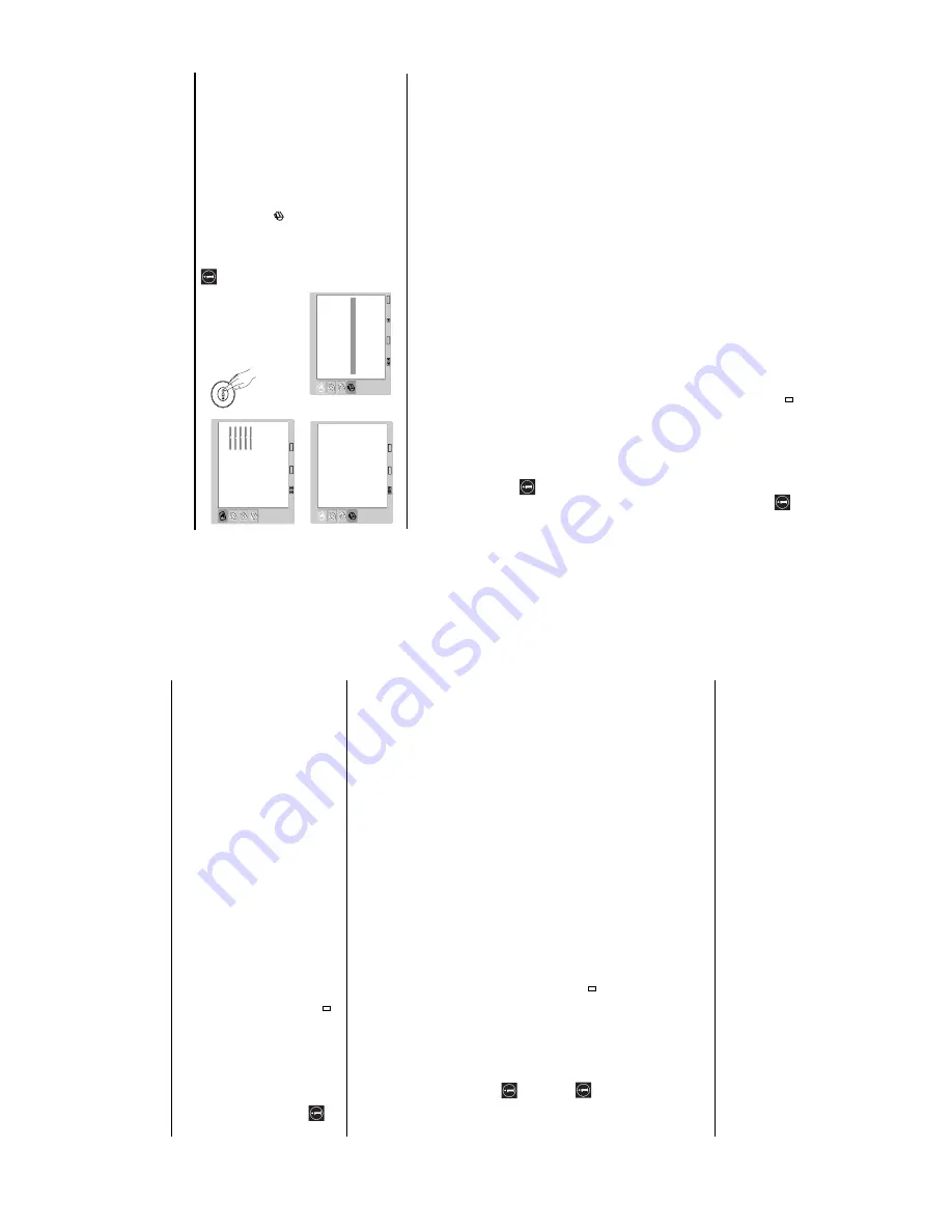
Picture Adjustment
Picture Mode
Contr
ast
Br
ightness
Colour
Shar
p
ness
Bac
klight
Reset
Noise Reduction
Colour T
o
ne
Select:
Set:
OK
End:
MENU
P
ersonal
80
50
50
50
70
A
uto
Nor
mal
Language
Countr
y
A
u
to T
u
ning
Prog
ra
mme Sor
ting
Prog
ra
mme Labels
A
V
Preset
Man
ual Prog
ramme Preset
English
United Kingdom
Set Up
Select:
Set:
OK
End:
MENU
Set Up
Language
Country
Auto Tuning
Programme Sorting
Programme Labels
AV Preset
Manual Programme Preset
English
United Kingdom
Select:
Set:
OK
End:
MENU
Back:
continued...
Summary of Contents for WEGA KLV-27HR3
Page 20: ... 19 WA1 RM Y1108 2 3 A BOARD REMOVAL 2 4 G2 BOARD REMOVAL ...
Page 21: ... 20 WA1 RM Y1108 2 5 H1 BOARD REMOVAL 2 6 H2 BOARD REMOVAL ...
Page 22: ... 21 WA1 RM Y1108 2 7 H3 BOARD REMOVAL 2 8 H5 BOARD REMOVAL ...
Page 23: ... 22 WA1 RM Y1108 2 9 LCD BRACKET REMOVAL 2 10 LCD ASSEMBLY REMOVAL ...