background image

22

WM-EX651

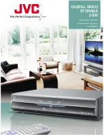
7-4. MECHANISM DECK SECTION-2 (MT-WMEX610-162)

Ref. No.

Part No.

Description

Remarks

Ref. No.

Part No.

Description

Remarks

151

152

154

153

163

162

161

159

156

155

154

158

157

160

160

PM901

151

3-010-274-21 TABLE, REEL

152

3-010-954-01 SPRING (BT), COMPRESSION

153

X-3377-584-5 CHASSIS ASSY (FA)

154

3-010-273-21 GEAR (REEL)

155

3-029-272-01 SPRING (FR), TORSION

156

3-040-897-04 SPRING (TGA), TORSION

157

3-029-285-02 GEAR, CAM

158

3-029-284-13 LEVER, TRIGGER

159

3-029-281-01 GEAR, IDLER (B)

160

3-029-283-02 GEAR, IDLER (A)

161

3-029-286-12 GEAR (NR)

162

3-029-273-01 GEAR (FR)

163

3-007-433-12 SHEET (N), REFLECTION

PM901

1-454-674-32 SOLENOID, PLUNGER

Summary of Contents for Walkman WM-EX651

Page 1: ...r requirements One rechargeable battery 1 2V DC x 1 One R6 size AA battery 1 5 V DC x 1 For charging stand DC IN 3 V jack AC power adaptor Dimensions w h d Approx 76 4 x 10⁸ 9 x 21 8 mm excl projecting parts and controls Mass Approx 140 g main unit only Supplied accessories Battery case 1 AC power adaptor 1 Charging stand 1 Stereo headphones or earphones with remote control 1 Rechargeable battery ...

Page 2: ...ble with ordinary solder It is best to use only unleaded solder but unleaded solder may also be added to ordinary solder SAFETY RELATED COMPONENT WARNING COMPONENTS IDENTIFIED BY MARK 0 OR DOTTED LINEWITH MARK 0 ON THE SCHEMATIC DIAGRAMS AND IN THE PARTS LIST ARE CRITICAL TO SAFE OPERATION REPLACE THESE COMPONENTS WITH SONY PARTS WHOSE PART NUMBERS APPEAR AS SHOWN IN THIS MANUAL OR IN SUPPLEMENTS ...

Page 3: ... the slider NR is set 3 The slider NR can be moved when the main power of the regulated power supply is turned OFF once then back ON Move the FWD REV switch S701 to the center position in synchronism with the timing when the slider NR is moved 3 FF REW modes 1 Check that the PRE SET status is set 2 Connect square wave or sine wave to TP53 P IN and TP14 GND See illustration below 3 Press the x swit...

Page 4: ...lley Idler Gear A S side Gear FR REW Right side Insert Flywheel N Insert Flywheel R Pulley Reverse Clutch Assy F Gear Y Cam Gear Gear REEL T side Motor Pulley Idler Gear A T side Gear FR FF Left side Insert Flywheel N Insert Flywheel R Pulley Reverse Clutch Assy F Idler Gear B Gear Y Cam Gear Gear REEL T side Gear REEL S side Motor Pulley Idler Gear A T side Idler Gear A S side Gear NR FWD Left si...

Page 5: ...struction manual There is a tactile dot beside VOL on the main unit to show the direction to turn up the volume The button has a tactile dot SPEED CONTROL OPEN x STOP bB PLAY REPEAT REW REVIEW FF CUE VOL HOLD Plug in firmly FWD HOLD VOL REW FF SOUND MODE bB x REV ...

Page 6: ...ELT F4 Page 7 HOLDER FS ASSY Page 9 MAIN BOARD Page 7 MAGNETIC HEAD HP901 Page 10 PINCH LEVER N R ASSY Page 10 MOTOR CAPSTAN REEL M901 Page 8 SET 1 lid battery case claw 2 screw M1 4 2 5 3 two screws M1 4 2 5 4 two screws M1 4 2 5 5 Remove the case assy in the direction of the arrow 3 1 DISASSEMBLY FLOW Note Follow the disassembly procedure in the numerical order given ...

Page 7: ...ard 2 Remove soldering six points from the head flexible boards 3 Remove soldering four points from the leaf switch 4 Remove soldering two points from plunger solenoid S701 6 two screws 5 Remove soldering four points from motor 3 belt F4 motor pulley insert flywheel R insert flywheel N pulley reverse 2 terminal board battery 1Remove soldering from the battery terminal board belt F4 ...

Page 8: ...8 WM EX651 3 5 MOTOR CAPSTAN REEL M901 3 6 CASSETTE LID ASSY 2 motor capstan reel M901 1 two screws M1 4 2 two screws M1 4 2 0 2 screw M1 4 2 0 4 cassette lid assy 1 Open the cassette lid 3 shaft ...

Page 9: ...5 ornament open assy 3 boss 4 two claws 2 claw 9 Remove soldering from six head flexible boards 0 Remove the holder FS assy in the direction of the arrow 8 shielded sheet 1 two screws ib lock 3 lock lever B 2 shaft 7 bracket cassette assy 6 shaft 4 screw M1 4 5 shaft ...

Page 10: ...0 MAGNETIC HEAD HP901 1 claw 2 Remove the pinch lever R assembly in the direction of the arrow 4 Remove the pinch lever N assembly in the direction of the arrow holder FS assy 3 claw 1 two claws 2 Remove the magnetic head HP901 holder FS assy ...

Page 11: ...ad demagnetizer 3 Do not use a magnetized screwdriver for the adjustments 4 The adjustments should be performed with the rated power supply voltage unless otherwise noted Torque Measurement Mode Torque Meter Meter Reading 14 7 to 24 5 mN m FWD CQ 102D 15 to 25 g cm 0 22 to 0 34 oz inch FWD 0 294 to 1 96 mN m Back Tension CQ 102D 0 3 to 2 0g cm 0 007 to 0 020 oz inch 14 7 to 24 5 mN m REV CQ 102C 1...

Page 12: ...de Through hole Pattern from the side which enables seeing 6 1 IC BLOCK DIAGRAMS IC301 TA2123AF EL PRE A PRE B MIX PW B PW A PW C BST MT TC BASE RF IN PW GND PW OUT R PW OUT C PW OUT L VCC RF OUT REF OUT BST NF BST OUT PW IN C LPF EQ L PW NF L PW IN L PW IN R PW NF R 3 REV IN L 5 PRE NF L 6 PRE OUT L 7 MTL DRV L 8 MTL DRV R 9 PRE OUT R 10 PRE NF R 11 AMS IN 12 REV IN R 4 FWD IN R 2 FWD IN L 1 21 2...

Page 13: ...BASE PW OUT L PW OUT R PW OUT C POWER AMP POWER AMP POWER AMP PW NF L BASS BOOST AMP PW IN L PW IN C BST OUT VOL RV301 HOLD S707 i J301 S901 2 ATS PRE OUT L MTL DRV L FWD IN L REV IN L L CH R CH FWD L CH R CH REV R CH R CH R CH R CH R CH R CH R CH R CH S701 DIRECTION OSC RESTART MOTOR MOTOR DIR AMS OUT F R SW M N SW 35 8 7 5 DR 6 10 9 11 W 3 V 1 U W V U 19 48 XT0 28 XT1 29 46 18 VCC 19 RF OUT 17 2...

Page 14: ...1 RV301 S901 TP60 220k 220k 47 4V 100 1k 1k 0 047 0 047 100 0 1 4700p 0 1 220k 1 470k 470k MA8062 1k 2 2 1 1 2 2 22k 0 22 0 22 1 0 1 2 2k 470k 2 2 6 3V 0 22 0 1 0 0 0 022 220 220 RT2N20M 4 7k 4 7k 0 22 0 22 220 220 470k 470k 1 1 1000p 1000p 2 2 2 2 4 7 4V 4 7 220 2V 4 7 4V 10k 22k 470P 47 2 5V 220p 47k 4 7k 47k 22k 22k 4 7k 0 022 1k 1k MA8062 2 2 6 3V 4 7 4V 1 1k 1k 1k 1 47 4V 2 2k 0 022 1000p 2SB...

Page 15: ...k 470k 470k 470k 100k 100k 220k 100k 10k 1k 1000p 32 768kHz 10p 0 1 1 MA8062 1 1 100k 10k 470 2 2k 4 7k PST9008NL 10k 470k 1 1 470k 220k 1k 4 7k 1000p 0 1 1k 220k 2 2M 10 10V 220k 47k 470k 470k 4 7 4V 470k 1M 4 7k SPEED CONTROL 470 DTC114TUA MOTOR RESEART P IN MA111 TX MA2ZD14001S0 MM1279XVBE XC6371C251PL S 817B11AMC CWAT2G 2SA1362YG PLUNGER DRIVE RT2N20M QUE REVIEW SWITCH MEGA BASS REVIVE VCC GND...

Page 16: ...1 R801 R702 R802 R711 R609 R608 R605 R601 C602 C604 R602 R611 Q603 C609 C702 IC702 S701 DIRECTION REV T STOP T FWD S707 C701 C310 C306 C303 RV301 Q604 Q301 Q702 RV601 TAPE SPEED TH601 D702 L701 D711 R717 R307 R746 R748 R747 R209 R109 R733 R720 R726 D710 D712 IC703 IC701 IC301 Q303 Q302 N VOL OFF ON 11 11 1 864 362 i J301 MAIN BOARD SIDEA HOLD 2 3 4 5 6 7 8 A 1 B C D E F Ref No Location D702 E 3 D7...

Page 17: ...55 TP34 SL301 SL302 CB301 C101 C201 C313 C301 C314 R111 R211 C108 C109 R120 R104 R105 C209 C208 C302 R204 R201 R202 R205 R102 R735 R714 R208 R108 R112 R212 R215 R704 R707 R715 R115 R729 R728 R730 S704 S703 R713 R727 R741 R734 R721 R103 R101 R207 R107 R302 R304 R309 R303 R203 R305 R220 R206 R106 R739 R706 R705 R708 R709 R738 R213 R214 R114 R306 R113 FB201 FB101 Q304 Q306 D701 Q701 TP31 TP46 TP45 TP...

Page 18: ...on detection circuit ON 19 MUTE CTL O Audio mute control signal output to TA2123AF L mute ON H mute OFF 20 SPCON C O Motor speed control cancel signal output high impedance cancel L normal 21 VDD1 Power supply 2 5 V 22 VSS Ground 23 VDD Power supply 1 1 V 24 VDDH Step up power supply terminal for back up 25 CB1 Terminal to which capacitor for step up power supply is connected 26 CB2 Terminal to wh...

Page 19: ... 355 21 BUTTON PLAY PINK 5 2 188 359 01 SHEET PLAY ADHESIVE 6 2 188 356 01 BUTTON STOP SILVER 6 2 188 356 11 BUTTON STOP BLUE 6 2 188 356 21 BUTTON STOP PINK 7 2 189 000 01 SHEET STOP ADHESIVE 8 2 188 354 01 PLATE ORNAMENTAL 9 2 188 353 01 RACK SPEED 10 2 189 001 01 SHEET ORNAMENTAL PLATE 11 3 225 873 09 SCREW M1 4 12 2 188 357 01 LID BATTERY CASE SILVER 12 2 188 357 11 LID BATTERY CASE BLUE 12 2 ...

Page 20: ...3 031 460 01 SHEET BT 58 X 3383 152 2 TERMINAL BOARD ASSY BATT 59 3 365 630 41 SCREW M1 4 60 X 3377 719 1 BRACKET CASSETTE ASSY M 61 X 3377 718 1 LEVER A ASSY M LOCK 62 3 224 837 01 SHEET ATS 63 3 038 054 02 LEVER B M LOCK 64 3 939 590 05 SCREW IB LOCK 65 X 3377 717 5 BRACKET ASSY M 66 3 389 523 02 SCREW IB LOCK 67 3 221 628 41 ORNAMENT OPEN SILVER 67 3 221 628 51 ORNAMENT OPEN BLUE 67 3 221 628 6...

Page 21: ...HER 105 3 029 276 02 WASHER STOPPER R 106 3 029 289 01 WASHER 107 3 007 428 01 WASHER R 108 3 029 288 11 PULLEY REVERSE 109 3 029 268 21 FLYWHEEL R INSERT 110 3 386 694 01 WASHER 111 3 029 306 21 FLYWHEEL N INSERT 112 3 220 035 01 BELT F4 113 3 029 282 12 GEAR Y 114 3 932 724 21 WASHER 115 X 3376 813 1 CLUTCH ASSY FM 116 3 029 765 01 SCREW M1 4 TOOTHED LOCK 117 3 029 274 21 RETAINER F2 MOTOR 118 X...

Page 22: ...E REEL 152 3 010 954 01 SPRING BT COMPRESSION 153 X 3377 584 5 CHASSIS ASSY FA 154 3 010 273 21 GEAR REEL 155 3 029 272 01 SPRING FR TORSION 156 3 040 897 04 SPRING TGA TORSION 157 3 029 285 02 GEAR CAM 158 3 029 284 13 LEVER TRIGGER 159 3 029 281 01 GEAR IDLER B 160 3 029 283 02 GEAR IDLER A 161 3 029 286 12 GEAR NR 162 3 029 273 01 GEAR FR 163 3 007 433 12 SHEET N REFLECTION PM901 1 454 674 32 S...

Page 23: ...64 360 11 CERAMIC CHIP 0 1uF 16V C309 1 115 467 11 CERAMIC CHIP 0 22uF 10 10V C310 1 135 149 21 TANTAL CHIP 2 2uF 10 10V C311 1 164 360 11 CERAMIC CHIP 0 1uF 16V C312 1 115 156 11 CERAMIC CHIP 1uF 10V C313 1 135 151 21 TANTAL CHIP 4 7uF 20 4V C314 1 135 149 21 TANTAL CHIP 2 2uF 10 10V C315 1 135 834 91 CERAMIC CHIP 2 2E 06PF 6 3V C316 1 125 837 91 CERAMIC CHIP 1uF 10 6 3V C317 1 135 834 91 CERAMIC...

Page 24: ...06 1 216 793 11 METAL CHIP 4 7 5 1 10W R307 1 216 825 11 METAL CHIP 2 2K 5 1 10W R309 1 216 853 11 METAL CHIP 470K 5 1 10W R601 1 216 837 11 METAL CHIP 22K 5 1 10W R602 1 216 809 11 METAL CHIP 100 5 1 10W R603 1 216 825 11 METAL CHIP 2 2K 5 1 10W R605 1 216 821 11 METAL CHIP 1K 5 1 10W R608 1 216 817 11 METAL CHIP 470 5 1 10W R609 1 216 829 11 METAL CHIP 4 7K 5 1 10W R701 1 216 829 11 METAL CHIP 4...

Page 25: ...ACK M901 1 763 166 15 MOTOR CAPSTAN REEL PM901 1 454 674 32 SOLENOID PLUNGER S901 1 762 553 11 SWITCH LEAF ATS TAPE DET ACCESSORIES A 1078 942 A REMOTE CONTROL ASSY RM WME25 0 1 478 423 11 ADAPTOR AC AC ES3010K KR 0 1 478 424 11 ADAPTOR AC AC ES3010K CH 1 478 978 11 STAND CHARGER BCA WMEX651 1 542 615 21 HEADPHONE MDR E708 1 756 306 22 BATTERY NICKEL HYDROGEN 1 759 700 22 CASE BATTERY 2 318 875 11...

Page 26: ...TORY Clicking the version allows you to jump to the revised page Also clicking the version at the upper right on the revised page allows you to jump to the next revised page Ver Date Description of Revision 1 0 2004 09 New ...

Reviews: