background image

GB 

10

Installing the Unit

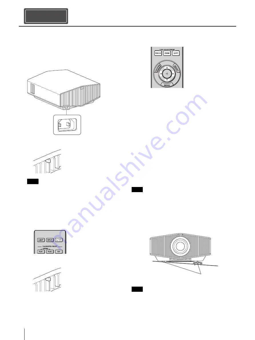
1

Position the unit so that the lens is parallel to 
the screen.

2

After connecting the AC power cord to the 
unit, plug the AC power cord into a wall outlet.

After connecting the AC power cord to the unit, the 
ON/STANDBY indicator may blink in orange.
You may not be able to control the unit while the 
indicator is blinking, but this is not a malfunction. Wait 
until it stops blinking and remains lit in red.

3

Press the 

/

 (On/Standby) button to turn on 

the unit.

4

Project an image on the screen, then adjust 
the focus, size, and position.

Adjust the focus.

Press the LENS ADJUSTMENT (FOCUS) button 
to display the Lens Focus adjustment window 
(test pattern). Then adjust the focus of the 
picture by pressing the 

/

/

/

 button.

Adjust the picture size.

Press the LENS ADJUSTMENT (ZOOM) button to 
display the Lens Zoom adjustment window 
(test pattern). Then adjust the size of the 
picture by pressing the 

/

/

/

 button.

Adjust the picture position.

Press the LENS ADJUSTMENT (SHIFT) button to 
display the Lens Shift adjustment window 
(test pattern). Then adjust to the proper 
position of the picture by pressing the 

/

/

/

 button.

Do not touch the lens when you adjust the image position. 
Your fingers may be pinched when the lens extends/
retracts.

To adjust the tilt of the installation surface

If the unit is installed on an uneven surface, use 
the front feet (adjustable) to keep the unit level.

Note that if the unit is tilted up or down, the projected 
image will be distorted in a trapezoidal shape.

Be careful not to pinch your fingers when rotating the 
front feet (adjustable).

Installing the Unit

Step 2

Note

Rear of the unit

ON/ST

ANDB

Y

Front of the unit

Lights in red.

ON/ST

ANDB

Y

Front of the unit

The ON/STANDBY indicator flashes 
in green, then it lights in green.

Note

Notes

Turn to adjust.

Front feet (adjustable)

Summary of Contents for VPL-XW6000

Page 1: ...Setup Guide_______________ Manuel de configuration __ Video Projector 5 038 072 11 1 2022 Sony Corporation VPL XW7000 VPL XW6000 Printed in China ...

Page 2: ...nstructions About This Manual Preparing Page 9 Installing the Unit Page 10 Connecting the Unit Page 12 Projecting Page 13 About Indicators Page 14 Dimensions Page 15 Step 1 Step 2 Step 3 Step 4 Manuals supplied Setup Guide this document Explains the installation and basic operations for projecting pictures Help Guide Web operating instructions Explains the features of the unit and how to use in de...

Page 3: ...perature place such as under direct sunlight or near fire It may ignite explode or cause a fire Do not immerse or wet the battery in water or seawater This may cause an electric shock CAUTION The following size and number of batteries are required for the remote control Size AA R6 Number of battery ies Two pieces To avoid risk of explosion use only the following type of battery Manganese batteries...

Page 4: ...es other than those specified herein may result in hazardous radiation exposure Caution The use of optical instruments with this product will increase eye hazard Location information of the labels Light source specifications 5 2 W laser diodes 24 Wavelength 450 460 nm Beam divergence angle from lens of this unit Zoom maximum α 39 9 Zoom minimum α 25 5 Supplier s Declaration of Conformity Trade Nam...

Page 5: ... may occur causing picture degradation or damage to the unit On repacking Save the original shipping carton and packing material they will come in handy if you ever have to ship your unit For maximum protection repack your unit as it was originally packed at the factory On watching 3D video images Safety precautions If you observe flickering or flashing turn off the lighting in the room Not for us...

Page 6: ...AVOIDABLE DATA LEAKS RESULTING FROM TRANSMISSION SPECIFICATIONS OR SECURITY PROBLEMS OF ANY KIND Depending on the operating environment unauthorized third parties on the network may be able to access the unit When connecting the unit to the network be sure to confirm that the network is protected securely From a safety standpoint when using the unit connected with the network it is strongly recomm...

Page 7: ... more than 30 cm 11 7 8 inches around the unit Hot and humid Locations subject to direct cool or warm air from an air conditioner Installing the unit in such a location may cause a malfunction of the unit due to moisture condensation or rise in temperature Near a heat or smoke sensor Malfunction of the sensor may occur Very dusty and extremely smoky locations Do not do any of the following while u...

Page 8: ...tain components Never mount the projector on the ceiling or move it by yourself Be sure to consult with qualified Sony personnel charged When installing the unit on a ceiling be sure to use a safety wire etc to prevent the unit from falling Entrust the installation to an experienced contractor or installer For dealers Be sure to secure the cabinet cover firmly when installing to the ceiling firmly...

Page 9: ...ove the lens cap before you use the projector Notes on the lens cap When removing the lens cap When removing the lens cap hold the parts other than the catches and pull it toward you If you pull while holding the catches the lens may be damaged When attaching the lens cap When attaching the lens cap be sure to hook the catches of the lens cap on the notches of the lens to prevent it from falling o...

Page 10: ...y the Lens Zoom adjustment window test pattern Then adjust the size of the picture by pressing the button Adjust the picture position Press the LENS ADJUSTMENT SHIFT button to display the Lens Shift adjustment window test pattern Then adjust to the proper position of the picture by pressing the button Do not touch the lens when you adjust the image position Your fingers may be pinched when the len...

Page 11: ...stalling the Unit Lens adjustment window test pattern The dashed lines show the angle of view of each aspect ratio 4 3 1 85 1 2 35 1 For more information refer to Installation and Connections in the Help Guide ...

Page 12: ...struction manual of the device to be connected Connecting the Unit When you monitor and control the projector via the network access the Setup page of the projector refer to Using Network Features in the Help Guide via a Web browser and enable the desired control protocol Step 3 HDMI cable not supplied Right side of the unit AV amplifier Speakers Computer Equipment with HDMI output connectors to H...

Page 13: ...Film 1 Image quality suited for reproducing the wide dynamic and clear images typical of master positive film CINEMA FILM 2 Cinema Film 2 Image quality suited for reproducing the rich tone and color typical of a movie theater based on Cinema Film 1 REF Reference Image quality suited for reproducing the original image quality faithfully or to enjoy the image quality without any adjustment TV TV Ima...

Page 14: ...ng indicators The number of flashes Cause and Remedy Three times The unit does not light properly due to an abnormality of the light source and light source power Turn off then turn on the power after a while If the symptom persists consult with qualified Sony personnel Twice The internal temperature is unusually high Check to ensure that nothing is blocking the ventilation holes and the unit is n...

Page 15: ... 4 3 8 210 1 8 9 32 5 3 16 Center of the lens 260 10 1 4 89 5 3 17 32 73 5 2 29 32 8 5 16 68 2 11 16 424 8 16 23 32 516 2 20 5 16 146 8 5 25 32 150 6 5 15 16 24 1 to 17 15 16 to 21 32 Holes for ceiling mount M5 Depth 8 5 16 Front of the cabinet Varies depending on how focus is adjusted ...

Page 16: ...of 6 4 mm 1 4 inches minimum to 8 0 mm 5 16 inches maximum for the ceiling mount Recommended tightening torque tension when turning a screw towards the direction of rotation 1 4 0 2 N m Note Unit Insert nut M5 Screw hole The minimum length of screw The maximum length of screw ...

Page 17: ...17GB ...

Page 18: ...en ligne À propos de ce manuel Préparation Page 25 Installation de l appareil Page 26 Raccordement de l appareil Page 28 Projection Page 29 À propos des indicateurs Page 31 Dimensions Page 32 Étape 1 Étape 2 Étape 3 Étape 4 Manuels fournis Manuel de configuration ce document Décrit l installation et les procédures de base de projection des images Guide d aide Mode d emploi en ligne Décrit les fonc...

Page 19: ...pe équivalent recommandé par le constructeur Lors de la mise au rebut de la batterie ou du produit vous devez respecter la loi de la région ou du pays concerné Ne mettez pas la batterie ou le produit au rebut dans un feu ou un four chaud ou n écrasez pas mécaniquement la batterie et ne la coupez pas Elle risque d exploser ou de provoquer un incendie Ne soumettez pas la batterie à une pression d ai...

Page 20: ... α 39 9 Zoom minimum α 25 5 Ne placez aucun objet devant l objectif pour éviter de bloquer la lumière durant la projection La chaleur provenant de la lumière risque d endommager l objet ÉTIQUETTE DE CLASSE 1 PICTOGRAMME ATTENTION RG2 Port d émission laser Pour les clients au Canada GARANTIE LIMITÉE DE SONY Rendez vous sur http www sonybiz ca pro lang en ca article resources warranty pour obtenir l...

Page 21: ... sécurité Si vous observez des scintillements ou des éclairs éteignez l éclairage Cet appareil n est pas destiné à être utilisé par des enfants sans la surveillance d un adulte À propos du contrôle des pièces de la source d éclairage Étant donné que l appareil utilise un laser une attention particulière et un environnement sûr sont nécessaires lors du réglage ou du contrôle des pièces de la source...

Page 22: ...vigateur Web pendant ou après la configuration Étant donné que l état de connexion est conservé dans le navigateur Web fermez ce dernier lorsque la configuration est terminée pour empêcher tout tiers non autorisé d utiliser l appareil ou d exécuter des programmes malveillants Lorsque vous connectez ce produit à un réseau connectez le via un système fournissant une fonction de protection tel qu un ...

Page 23: ... 30 cm 11 7 8 pouces autour de l appareil Endroits chauds et humides Endroits directement exposés au souffle froid ou chaud d un climatiseur L installation de l appareil dans de tels endroits pourrait provoquer un dysfonctionnement sous l effet de la condensation d humidité ou de l élévation de température Proximité d un détecteur de chaleur ou de fumée Il pourrait en résulter un dysfonctionnement...

Page 24: ...lité de certains composants Ne montez jamais le projecteur au plafond et ne le déplacez jamais par vos propres moyens Veillez à vous adresser à un technicien Sony agréé service payant Pour installer l appareil au plafond veillez à utiliser un fil de sécurité etc pour empêcher la chute de l appareil Confiez l installation à un prestataire ou à un installateur expérimenté Pour les revendeurs Veillez...

Page 25: ...on d objectif avant d utiliser le projecteur Remarques relatives au capuchon d objectif Lors du retrait du capuchon d objectif Pour retirer le capuchon d objectif maintenez les pièces autres que les crochets et tirez le vers vous Si vous le tirez tout en maintenant les crochets vous risquez d endommager l objectif Lors de la fixation du capuchon d objectif Pour fixer le capuchon d objectif veillez...

Page 26: ...int de l image en appuyant sur le bouton Réglez la taille de l image Appuyez sur le bouton LENS ADJUSTMENT ZOOM pour afficher la fenêtre de réglage Zoom d objectif mire d essai Réglez ensuite la taille de l image en appuyant sur le bouton Réglez la position de l image Appuyez sur le bouton LENS ADJUSTMENT SHIFT pour afficher la fenêtre de réglage Déplac objectif mire d essai Réglez ensuite la posi...

Page 27: ...zoïdale Veillez à ne pas vous pincer les doigts lors de la rotation des pieds avant réglables Fenêtre de réglage de l objectif mire d essai Les lignes pointillées indiquent l angle de vue de chaque rapport de format Remarques 4 3 1 85 1 2 35 1 Pour plus d informations reportez vous à la section Installation et raccordements du Guide d aide ...

Page 28: ...ode d emploi du périphérique à raccorder Raccordement de l appareil Pour surveiller et commander le projecteur via le réseau accédez à la page Configuration du projecteur reportez vous à la section Utilisation des fonctionnalités réseau du Guide d aide via un navigateur Web et activez le protocole de contrôle souhaité Étape 3 Câble HDMI non fourni Côté droit de l appareil Amplificateur AV Haut par...

Page 29: ... Projection de l image Mise hors tension Remarque Sélection du mode d affichage de l image Paramètres Description CINEMA FILM 1 Cinéma Film 1 Qualité d image adaptée à la reproduction d images hautement dynamiques et nettes typiques d un chef d œuvre du cinéma CINEMA FILM 2 Cinéma Film 2 Qualité d image adéquate pour la reproduction de tons riches et de couleurs dignes du cinéma en fonction de l o...

Page 30: ... image adéquate pour regarder des contenus IMAX Enhanced Appuyez sur le bouton MENU et sélectionnez parmi Prérégl étalon dans le menu Image Paramètres Description Pour plus d informations reportez vous à la section Projection du Guide d aide ...

Page 31: ...lignotements Cause et remède Trois fois L appareil ne s allume pas correctement en raison d une anomalie de la source lumineuse et de l alimentation de la source lumineuse Mettez hors tension l appareil puis remettez le sous tension Si ce symptôme persiste consultez le service après vente Sony Deux fois La température à l intérieur du projecteur est anormalement élevée Assurez vous que rien ne col...

Page 32: ...10 1 8 9 32 5 3 16 Centre de l objectif 260 10 1 4 89 5 3 17 32 73 5 2 29 32 8 5 16 68 2 11 16 424 8 16 23 32 516 2 20 5 16 146 8 5 25 32 150 6 5 15 16 24 1 à 17 15 16 à 21 32 Trous pour le montage au plafond M5 profondeur 8 5 16 Avant du boîtier Cela varie en fonction du réglage de mise au point ...

Page 33: ... 1 4 pouces minimum à 8 0 mm 5 16 pouces maximum pour le montage au plafond Couple de serrage recommandé tension au moment de faire tourner les vis dans le sens de rotation 1 4 0 2 N m Remarque Appareil Écrou d insertion M5 Trou de vis Longueur minimale de la vis Longueur maximale de la vis ...

Page 34: ......

Page 35: ......

Reviews: