background image

Connecting a Power Source

9

Connecting a Power Source

You can use either AC power or a rechargeable battery pack as a power 
source.

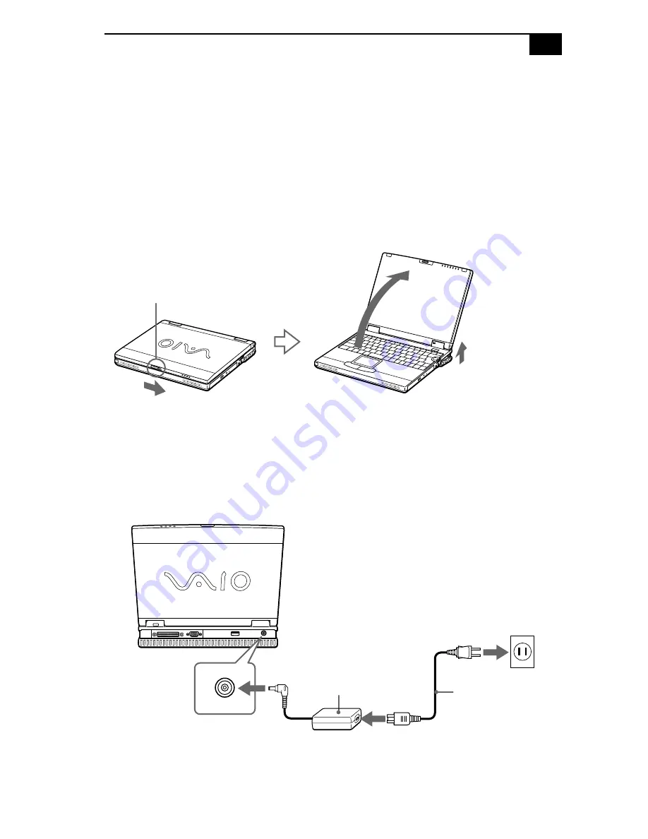
Using the AC Adapter

1

Slide the LCD lock lever in the direction of the arrow as indicated 
below, and lift the cover. The bottom portion of the computer lifts 
automatically and the back connectors appear.

2

Plug the cable attached to the AC adapter into the DC In connector on 
the computer.

3

Plug one end of the power cord into the AC adapter.

4

Plug the other end of the power cord into an electrical outlet.

LCD lock lever

Power cord (supplied)

AC adapter (supplied)

DC In

Notebook

Summary of Contents for VAIO PCG-XG18

Page 1: ...VAIO Notebook User Guide PCG XG18 PCG XG19 ...

Page 2: ...ge Subscriptions to online service providers may require a fee and credit card information Financial services may require prior arrangements with participating financial institutions As an ENERGY STAR Partner Sony Corporation has determined that this product meets the ENERGY STAR guidelines for energy efficiency The International ENERGY STAR Office Equipment Program is an international program tha...

Page 3: ...le Pour prévenir tout risque d incendie ou d électrocution garder cet appareil à l abri de la pluie et de l humidité Pour prévenir tout risque d électrocution ne pas ouvir le châssis de cet appareil et ne confier son entretien qu à une personne qualifiée L appareil doit être le plus près possible d une prise murale pour en faciliter l accès For questions regarding your product or for the Sony Serv...

Page 4: ...ipherals that are not shielded and grounded may result in interference to radio and television reception FCC Part 68 This equipment complies with Part 68 of the FCC rules On the bottom of this equipment is a label that contains among other information the FCC equivalence number REN for this equipment If requested this information must be provided to the telephone company This modem uses the USOC R...

Page 5: ... or on the first page of the transmission the date and time it is sent and an identification of the business other entity or individual sending the message and the telephone number of the sending machine or such business other entity or individual In order to program this information into your facsimile machine see your fax software documentation Telephone Consumer Guidelines Canada Please refer t...

Page 6: ... electric inspection authority or electrician as appropriate NOTICE The Ringer Equivalence Number REN assigned to each terminal device provides an indication of the maximum number of terminals allowed to be connected to a telephone interface The termination on an interface may consist of any combination of devices subject only to the requirement that the sum of the Ringer Equivalence Numbers of al...

Page 7: ...nications comme le prescrivent les documents concernant les exigences techniques relatives au matériel terminal Le Ministère n assure toutefois pas que le matériel fonctionnera à la satisfaction de l utilisateur ...

Page 8: ... propre protection l utilisateur doit s assurer que tous les fils de mise à la terre de la source d énergie électrique des lignes téléphoniques et des canalisations d eau métalliques s il y en a sont raccordés ensemble Cette précaution est particulièrement importante dans les régions rurales Avertissement L utilisateur ne doit pas tenter de faire ces raccordements lui même il doit avoir recours à ...

Page 9: ...tors 5 Front 5 Left 6 Right 7 Back 7 Bottom 8 Connecting a Power Source 9 Using the AC Adapter 9 Starting Your Computer 14 Shutting Down Your Computer 15 Closing the Front Panel 16 Registering Your Computer 17 VAIO Action Setup 18 Jog Dial Control 18 Using the Jog Dial Control 20 Software that does not support the Jog Dial Control 21 Internal Timer 22 i LINK Interface 22 ...

Page 10: ...Idle Mode 42 System Suspend Mode 43 System Hibernation Mode 43 Using a Second Battery Pack 44 Connecting Peripheral Devices 47 Connecting a Phone Line 48 Connecting the Mini Docking Station 49 Connecting a Printer to the Mini Docking Station 54 Connecting an External Mouse or Keyboard 55 Connecting a Floppy Disk Drive to the Mini Docking Station56 To connect a floppy disk drive 56 Connecting AV De...

Page 11: ...onnecting a Universal Serial Bus USB Device 67 Getting Help 69 Troubleshooting 71 Power Management 78 Using the System and Application Recovery CDs 79 Using the System Recovery CD s 79 Using the Application Recovery CD s 81 Changing the Window design of Sony Software 82 Replacing a Keycap 83 To replace a keycap 83 Adding Memory 84 Specifications 88 Index 91 ...

Page 12: ...xii ...

Page 13: ...eable battery pack provides hours of use without AC power Sony audio and video quality A high resolution LCD screen enables you to take advantage of today s advanced multimedia applications games and entertainment software Microsoft Windows Operating System Your system includes Windows 98 Second Edition Communications Access popular online services send and receive e mails browse the Internet and ...

Page 14: ...ing hardware items from the box Main unit Floppy disk drive Power cord DVD ROM drive Accessory case AC adapter Weight saver Battery pack FDD drive cable INSIDE ACCESSORY CASE 1 AC adapter FDD drive FDD drive cable cables battery pack and weight saver INSIDE ACCESSORY CASE 2 ...

Page 15: ...e most up to date information on using your computer and software information The Consumer Information Guide contains ergonomic considerations and your computer s limited warranty statement The Microsoft Getting Started manual explains how to use the basic features of the Windows operating system Software CDs Microsoft Word 2000 Recovery CDs System Recovery CD s Application Recovery CD s Other Set...

Page 16: ...4 ...

Page 17: ...cating the Controls and Connectors Front Power indicator pages 14 43 LCD Liquid Crystal Display screen pages 16 27 Battery 1 and 2 indicators pages 11 26 Keyboard page 23 Hard disk drive indicator page 26 Speakers pages 27 74 75 Num Lock indicator page 26 Internal microphone Caps Lock indicator page 26 Touchpad page 29 Scroll Lock indicator page 26 Left right buttons page 29 1 7 2 8 3 9 4 10 5 11 ...

Page 18: ...VAIO Notebook User Guide 6 Left PC card slots page 36 Battery bay page 10 S400 i LINK connector page 66 Phone line jack PCG XG18 page 48 PCG XG19 PCG XG18 1 3 2 4 ...

Page 19: ...ne connector page 71 Multipurpose bay pages 32 47 Headphone connector page 70 Jog Dial control page 18 Intercooler flap Infrared port connector page 40 USB connector page 73 Docking Floppy disk drive connector DC In connector page 8 Monitor connector page 66 1 4 2 5 3 6 1 4 2 5 3 ...

Page 20: ...VAIO Notebook User Guide 8 Bottom Intercooler flap lever Multipurpose bay RELEASE lever 1 2 ...

Page 21: ... arrow as indicated below and lift the cover The bottom portion of the computer lifts automatically and the back connectors appear 2 Plug the cable attached to the AC adapter into the DC In connector on the computer 3 Plug one end of the power cord into the AC adapter 4 Plug the other end of the power cord into an electrical outlet LCD lock lever Power cord supplied AC adapter supplied DC In Noteb...

Page 22: ...t the time of purchase Follow the steps below to insert and charge the battery pack To insert the battery pack 1 Open the cover of the battery bay on the left side of the computer 2 Insert the battery pack into the battery bay 3 Close the cover of the battery bay until it clicks While attaching the Mini Docking Station to your computer do not insert or remove the battery pack Lifting and turning t...

Page 23: ... Information in the online manual Customizing Your Notebook There are two battery indicator lights on the computer Battery Indicator Meaning 1 Indicates the status of the battery pack in the battery bay on the left side of the computer 2 Indicates the status of the battery pack in the drive bay on the right side of the computer Battery Indicator Light Status Meaning On The computer is using batter...

Page 24: ...ry or shut down your computer and insert a fully charged battery You can extend battery life by changing the power management modes in the PowerPanel utility See Using Power Saving Modes on page 42 The battery pack supplied with your computer is a lithium ion battery and can be recharged at any time Charging a partially discharged battery does not affect battery life The battery indicator light is...

Page 25: ...ver of the battery bay 2 Pull out the battery pack 3 Close the cover of the battery bay You may lose data if you remove the battery pack while the computer is on and not connected to the AC adapter or if you remove the battery while the computer is in System Suspend mode ...

Page 26: ...e green power indicator light turns on 3 If necessary adjust the brightness controls for the LCD display To decrease the brightness press Fn F5 and then the down or left arrow key To increase the brightness press Fn F5 and then the up or right arrow key If you press the power button for more than four seconds the computer turns off LCD lock lever Power button Power indicator ...

Page 27: ...puter To avoid potential loss of data follow these steps to shut down your computer Respond to any prompts warning you to save documents If you are unable to shut down your computer using the steps described above close all software in use remove the PC cards if inserted disconnect any USB devices end any Infrared Communication devices Then restart the computer If the previous steps do not work se...

Page 28: ...ve fingerprints on the LCD screen Use the supplied filter cleaner to wipe the LCD screen See Notes on Use for more information To close the intercooler flap The bottom part of the computer does not close automatically To close the intercooler flap grasp both sides of the flap with your thumbs while sliding the levers with your index fingers clip Intercooler flap lever ...

Page 29: ...your VAIO notebook to Sony for service of your computer If you have not already registered follow these steps to use your notebook s online registration service 1 Click the Sony VAIO Registration icon on the VAIO desktop 2 Enter the information requested on the first online registration form Press the Tab key to move from box to box 3 Click the Next button to advance to the next form 4 Complete th...

Page 30: ... Control Your computer is equipped with a Jog Dial on the right side of the unit The Jog Dial control enables you to open an application folder or document from a predefined list by rotating and pressing the Jog Dial control In addition when you press the Jog Dial control you can turn on your computer automatically and start the selected application or document and if the document you select is a ...

Page 31: ... of that item by selecting it and pressing the Jog Dial control button Guide mode The Jog Dial control window is in the guide mode when software is in use and the software window is active Depending on the software you are using you can select items from the displayed list using the Jog Dial control Some Sony software applications have two modes in List View Simple Menu and Full Menu You can switc...

Page 32: ... the Jog Dial control window or the Jog Dial control icon in the task tray Alternatively you can press the Jog Dial control while pressing the Ctrl key on the keyboard to switch to the launcher mode 1 Turn the Jog Dial control to select the item you want then press the Jog Dial control The window switches to the guide mode and shows the Jog Dial s function 2 Turn or press the Jog Dial control to u...

Page 33: ...as described below Some software does not support these functions Action Description Maximize Window Press the Jog Dial control button to maximize the size of the active window Press again to return to normal window size Minimize Window Press the Jog Dial control button to minimize the size of the active window Press again to return to normal window size Finish Window Press the Jog Dial control bu...

Page 34: ... application at a specific time The timer can start applications even when the computer is in system hibernation mode i LINK Interface Your computer comes equipped with an i LINK port The port is a digital interface IEEE 1394 for high speed communication By using your computer a Sony Digital Handycam Camcorder or other camera that supports the i LINK interface you can easily create and edit your o...

Page 35: ...ack in its place and push down gently until it clicks into place If the Enter key Space key or Shift key comes off see Replacing a Keycap on page 83 Do not take off the keycaps intentionally or push excessively when replacing them as this may cause the unit to malfunction Escape Key Function keys Print Screen key Shift key Ctrl key Fn key Windows 98 key Applications key Navigation keys Numeric key...

Page 36: ... snapshot of the screen and places it in the Windows Clipboard You can then paste the screen shot into a document and print it Operator keys Several keys are always used with at least one other key Ctrl Alt and Shift When held down with another key the Ctrl Control and Alt Alternate keys offer another way to give commands For example in many applications instead of choosing the Save command from a...

Page 37: ... then Files or Folders from the Start menu Ctrl F Displays the Windows Find Computer window where you can locate other computers This is the equivalent of selecting Find and then Computer from the Start menu M Minimizes all displayed windows Shift M Returns all minimized windows to their previous size R Displays the Run window This is the equivalent of selecting Run from the Start menu Fn Insert D...

Page 38: ...ard disk Lights when data is being read from or written to the hard drive Do not enter System Suspend mode or turn off the computer when this indicator light is on Light On Off Num Lock The number keys in the numeric keypad are active The alphanumeric character keys in the keypad area are active Caps Lock The letters appear in uppercase as you type The Shift key lowers the case of typed letters wh...

Page 39: ...ensity press Fn F5 and then or To decrease light intensity press Fn F5 and then or Fn F7 Switch to the external display LCD Toggles through the LCD external display connected to the Monitor connector and both LCD and external display Fn F8 Toggles through the external display connected to an optional Mini Docking Station PCGA PSX1 and the LCD Fn F12 System Hibernation Provides for the lowest level...

Page 40: ...play is set to a low resolution Fn S System Idle Puts the system into System Idle mode a power management state To return the system to the active state press any key You can carry out these functions except for Fn D and Fn F using the Jog Dial control See Using the Jog Dial Control on page 20 for more information Some functions are not available until Windows launches Combinations Feature Functio...

Page 41: ...f context sensitive choices Drag Slide one finger while pressing the left button Scroll Move your finger along the right edge of the touchpad to scroll vertically Move your finger along the bottom to scroll horizontally The scroll function is available only with applications that support a touchpad scroll feature See Mouse Help for information on touchpad features such as clicking both buttons sim...

Page 42: ...also connect the floppy disk drive while in power saving mode See also To insert to remove the disk drive while in power saving mode in the online manual To Use as an External Drive Connect the floppy disk drive to the computer using the floppy disk drive cable supplied with the VAIO logo facing up Align the logo on the cable with the slot connection and insert the connector straight into the slot...

Page 43: ...ose bay with the VAIO logo facing up Continue pushing the drive into the bay until the RELEASE lever locks into place To insert a diskette 1 Hold the diskette with the label side facing up 2 Gently push the diskette into the drive until it clicks into place To remove a diskette When you finish using the diskette wait until the LED indicator turns off and then press the Eject button to remove the d...

Page 44: ...DD instead 2 Slide the RELEASE lever on the bottom of the computer in the direction of the arrow and slide the drive out of the multipurpose bay 3 Click OK on the message screen When the multipurpose bay is empty attach the weight saver to it See step 3 of Using a Second Battery Pack on page 44 for details on attaching the weight saver Do not press the Eject button when the LED indicator is turned...

Page 45: ... with the label side facing up For DVDs which can be played on both sides the side of the disc facing up is the side that plays Push the disc onto the hub until the disc clicks into place When the computer is in System Suspend or System Hibernation mode you cannot insert a disc See Controlling Power Management in the online document Customizing Your VAIO Notebook for more information on System Sus...

Page 46: ... the disc firmly you could damage your DVD ROM drive and you may not be able to open the tray When you finish using a disc wait until the LED indicator light turns off then press the Eject button to remove the disc When the computer is in System Suspend or System Hibernation mode you cannot remove a disc See Controlling Power Management in the online document Customizing Your VAIO Notebook for mor...

Page 47: ... DVD ROM drive while the computer is in power saving mode When playing DVD movies on battery power set the power management profile to DVD profile With other profiles the movies are choppy As an alternative you can set the power management profile to Automatic Profile Selection which will cause the DVD profile to be selected automatically whenever you insert a DVD See Controlling Power Management ...

Page 48: ...lots are compatible with Card Bus Some PC cards may require that you disable idle devices when using the PC card You can use Sony Notebook Setup to disable devices See Displaying the Sony Notebook Setup Screen in the online Customizing Your Notebook manual for details Be sure to use the most recent software driver provided by the PC card manufacturer If an mark appears on the Device Manager tab in...

Page 49: ...d to remove both the top and bottom PC card slot protectors 3 Insert the PC card into the PC card slot front label facing up Gently push the card into the slot until the card is fixed into the connector The RELEASE button comes out Knock down the RELEASE button toward the display panel PC card ...

Page 50: ... 5 Press the RELEASE button to remove the PC card Insert the PC card slot protector back into the empty slot Do not force a card into the slot as this may damage the connector pins If you have difficulty inserting a card check that you are inserting the card with the correct orientation See the manual that came with your PC card for more information on use For some PC cards if you alternate betwee...

Page 51: ...cables with the following part numbers VMC IL4415 a 1 5 meter cable with a 4 pin connector at each end VMC IL4615 a 1 5 meter cable with a 4 pin connector at one end and a 6 pin connector at the other end and VMC IL4408A a 0 8 meter cable with a 4 pin connector at each end When you use Smart Connect to connect two VAIO computers you must assign each computer a unique name by which it can be identi...

Page 52: ...located on the left side You can use this port to communicate with other infrared equipped devices with compatible protocols such as a digital still camera or other computers To use infrared communication with another computer Align the infrared ports on the two computers so that they are in a direct line ...

Page 53: ...he Infrared Monitor in the Windows Control Panel to determine if the infrared device is detected If the two devices are too far apart or too close together data transfer may be interrupted or there may be noise in the transmission Do not cover the infrared ports with your hand or any other object Avoid direct sunlight fluorescent light or flashing incandescent light near the infrared ports See the...

Page 54: ...anagement setting you select Normal Mode This is the normal state of your computer when it is in use The green power indicator light is on in this mode To save power you can turn off a specific device such as the LCD System Idle Mode This mode is convenient if you do not need to use your computer for a brief period The hard disk and video display enter a low power state and the CPU clock and proce...

Page 55: ...ctivate System Hibernation mode Press Fn F12 The Save to Disk Manager screen appears and then the computer enters System Hibernation mode You can also use the PowerPanel utility or the Jog Dial control to enter System Hibernation mode To return to normal mode Turn on the computer by pressing the power button The computer returns to its previous state Time to return to normal mode System Idle requi...

Page 56: ...by observing the battery indicator lights To insert a second battery pack 1 If another device is in the multipurpose bay remove the device See To remove the DVD ROM drive on page 35 2 Insert the battery pack into the multipurpose bay If the battery is being used the battery 2 indicator light turns on 3 Attach the weight saver to the computer to stabilize the battery pack Insert the tab of the weig...

Page 57: ...bottom of the computer in the direction of the arrow See also To remove the floppy disk drive on page 32 2 Remove the weight saver and then pull out the battery pack 3 Reinsert the weight saver If you attach two battery packs you can remove either of them without shutting down the computer When removing one battery pack make sure that the other battery pack s indicator is on If the indicator of th...

Page 58: ...46 ...

Page 59: ...Printer page 60 External display page 62 External speakers page 64 External microphone page 65 i LINK compatible device page 66 Universal Serial Bus USB device page 67 Connect the power cord only after connecting all cables Turn on the computer only after turning on all peripherals You can select a country mode from the modem property window but you should only use US mode Using other country mode...

Page 60: ...ur software online and use Sony Customer Support you must connect to a phone line You must register your computer to receive the extended warranty Your computer does not work with party lines cannot be connected to a coin operated telephone and may not work with multiple phone lines or a private branch exchange PBX Some of these connections might result in excess electrical current and could cause...

Page 61: ...ripheral devices such as a printer or external display Back S400 DC IN S VIDEO Mouse Keyboard VIDEO OPTICAL OUT Monitor CONTROL A1 LINE OUT SERIAL CONTROL A1 switch LINE IN Serial USB CONTROL A1 IN USE indicator DC IN indicator RELEASE lever UNDOCK button Docking connector Tabs 1 8 6 5 2 4 7 3 7 13 9 10 12 14 11 1 8 2 9 3 10 4 11 5 12 6 13 7 14 ...

Page 62: ...d to the AC adapter into the DC IN connector on the Mini Docking Station Plug the power cord into the AC adapter and an electrical outlet The DC IN indicator lights on Use the specified AC adapter for the power rating of the Mini Docking Station Floppy disk drive connector PC card slot AC adapter supplied Power cord ...

Page 63: ... back of your computer When a charged battery is inserted in your computer you can attach and detach the Mini Docking Station without turning off the computer 1 Open the cover of your computer 2 Attach the left side tab of the Mini Docking Station to the left side hollow of your computer Push the tab into the hollow firmly until it clicks Docking FDD connector ...

Page 64: ...e tab into the hollow firmly until it clicks To remove the Mini Docking Station from your computer 1 Press the UNDOCK button on the Mini Docking Station or click REMOVE on the Start menu Do not lift or move the computer by holding only the Mini Docking Station as the Mini Docking Station may be removed from the computer UNDOCK button ...

Page 65: ...right side of your computer and release the right tab 3 Release the left tab When the Mini Docking Station is attached to your computer do not insert or remove the battery The Mini Docking Station may be removed from the computer Do not remove the Mini Docking Station when the IN USE indicator is lit RELEASE lever ...

Page 66: ... all the connections Turn on the peripheral devices before turning on your computer If you are using a printer that does not support Windows 98 it may not function properly You can connect a printer while the floppy disk drive is in use When using a USB printer connect it to the USB connector of your computer or of the Mini Docking Station See the manual that came with your printer for more inform...

Page 67: ...mouse to the serial port using the PS 2 serial adapter that is supplied with your mouse See Using the Keyboard on page 23 for more information on using the keyboard See the manual that came with your mouse or keyboard for more information on installation and use Before you connect or disconnect the mouse or keyboard turn off the computer Do not connect or disconnect the PS 2 device keyboard or mou...

Page 68: ...hout turning off your computer To connect a floppy disk drive Plug the cable firmly into the connector with the VAIO logo facing up and both of the alignment posts in the guide holes When you connect the floppy disk drive to the floppy disk drive connector of the Mini Docking Station you cannot use the PRINTER connector of the floppy disk drive cable Floppy disk drive cable supplied Floppy disk dr...

Page 69: ...OL A1 connector you can play a CD disc create your own CD database or edit an MD disc To use the CONTROL A1 connector on the Mini Docking Station switch the SERIAL CONTROL A1 switch to CONTROL A1 CONTROL A1 or CONTROL A1 Use monaural mini plug cables shorter than 2 meters with no resistance MD deck CD player To OPTICAL OUT To Digital In To CONTROL A1 To Digital Out Optical Digital cable Monaural m...

Page 70: ...e click YAMAHA DS XG Audio Config 3 Select Digital Output and click ON All Sources Analog out is muted 4 Click OK To connect a CD player an active speaker or an amplifier Connect a CD player an active speaker or an amplifier to the LINE IN or LINE OUT connector of the Mini Docking Station to play a CD disc and experience higher quality audio Active speaker amplifier etc CD player etc Mini Docking ...

Page 71: ...guration system See To select the display in the Customizing Your Notebook manual for more information Switch the Digital output to PCM when you connect a device that does not support Dolby Digital otherwise the speakers or your hearing may be damaged by the increased volume Switch the Digital output to PCM when you play DVDs that support linear PCM recording on the Mini Docking Station Unplug the...

Page 72: ... came with your printer for more information You need to set up the printer s port See I cannot print on page 78 for more information about setting up the printer ports To connect a printer Plug the floppy disk drive cable to the docking FDD connector on your computer Then connect the printer cable supplied with the printer to the PRINTER connector of the floppy disk drive cable Printer Power cord...

Page 73: ...d after finishing all the connections Turn on the peripheral devices before turning on your computer If you are using a printer that does not support Windows 98 it may not function properly You can connect a printer while the floppy disk drive is in use When using a USB printer connect it to the USB connector of your computer or of the USB connector of the Mini Docking Station ...

Page 74: ...n page 65 for details on connecting external speakers and an external microphone Turn off your computer and all peripherals and disconnect the AC adapter and power cord from the AC outlet before making connections Connect the power cord after connecting all peripherals Turn on your computer after turning on the power of all peripherals When you connect an external display you may not be able to di...

Page 75: ...vices Use the Fn F7 keys to select a display See also Selecting the Display Mode in the Customizing Your Notebook manual for more information See the manual that came with your projector for more information on installation and use To Press Result Switch to an external display Fn F7 Toggles among the LCD the external display connected to the Monitor connector and both the LCD and external display ...

Page 76: ...fore connecting the cables Connect all the cables before plugging in the power cord Turn on the peripheral devices power then turn on your computer Make sure your speakers are designed for computer use Turn down the volume of the speakers before you turn them on Do not place diskettes on the speakers the speakers magnetic field may damage the data on the diskettes See the manual that came with you...

Page 77: ... this connector Shut down the computer and all peripheral devices before connecting the cables Connect all the cables before plugging in the power cord Turn on the peripheral devices power then turn on your computer Make sure your microphone is designed for computer use The microphone should be compliant with the plug in power microphone See the manual that came with your microphone for more infor...

Page 78: ...upply power to external devices If the external device requires power from the i LINK connector you cannot use the device with the computer The computer supports transfer rates up to 400 Mbps however the actual transfer rate depends on the external device The i LINK features available may vary depending on the software applications you use See the documentation that came with your software for mor...

Page 79: ...ou can use the optional Sony USB mouse PCGA UMS1 with this computer The USB mouse software driver is preinstalled in the computer Therefore you only need to plug the USB mouse into the USB connector See the manual that came with your USB device for more information on installation and use to USB device USB USB connecting cable not supplied ...

Page 80: ...68 ...

Page 81: ...tebook The electronic document contains additional information on customizing your computer You can access this guide from the Windows Start menu by selecting Help Center Step 1 Documentation 4 Manuals and online help files that may accompany your preinstalled software Most of the manuals for preinstalled software are located on your hard disk drive as online help files You can access the online h...

Page 82: ...topics that you want to receive To contact the Sony fax on demand service call 1 888 4SONYPC 1 888 476 6972 Requires a fax machine or your fax software 7 Calling Sony Customer Support You can call and speak with a Sony Customer Support Representative without using your computer by calling 1 888 4SONYPC 1 888 476 6972 Software support is available free of charge for 90 days after the original date ...

Page 83: ...ng an external display check that it is plugged into a power source and turned on Check that the brightness and contrast controls are adjusted correctly See the manual that came with your display for details Moisture condensation may have occurred Do not use the computer for at least one hour and then turn on the computer Take the battery pack off the computer unplug the power cord and plug it aga...

Page 84: ... again Confirm that Windows starts properly If Windows still does not start follow the procedure below to initialize the BIOS If the floppy disk drive is empty follow the steps below to initialize the BIOS 1 Remove any peripheral devices connected to the computer 2 Turn off the computer and then turn it on again 3 Turn on the computer and press the F2 key when the Sony logo appears The BIOS setup ...

Page 85: ...lick Restart the computer If you cannot restart as described in the preceding step you can restart the computer by pressing Ctrl Alt Delete If the previous step does not work press the power button and hold it for at least four seconds This turns off the power My software program locks up or crashes Contact the software publisher or designated provider for technical support See the Read Me First f...

Page 86: ...8 bar and select Shut Down to display the Shut Down Windows dialog box then press Enter If you cannot turn off the computer as described in the step above press Ctrl Alt Delete to restart the computer If nothing occurs doing the step above press the power button for more than four seconds to turn off the computer If the pointer does not move while playing a disc press Ctrl Alt Delete to stop playb...

Page 87: ... you connect external speakers check that the speakers are properly connected and the volume is turned up If the speakers have a mute button make sure it is off If the speakers are powered by batteries check that the batteries are inserted properly and that they are charged If you have connected an audio cable to the Headphone connector disconnect the cable My modem does not work Check that the ph...

Page 88: ...vice Provider check that the ISP is not experiencing technical problems If you have a second phone line available try connecting the modem to that line My microphone does not work If you are using an external microphone check that the microphone is plugged into the Microphone connector See Connecting an External Microphone on page 65 for details My mouse does not work If you are using an external ...

Page 89: ...computer using the Shut Down command on the Windows Start menu Using other methods including those listed here may result in loss of unsaved data If the Shut Down command does not work properly follow these steps Restart the computer by pressing Ctrl Alt Delete If this does not work press the power button and hold it for at least four seconds to turn off the power Unplug the computer from the AC a...

Page 90: ...devices connected to the Mini Docking Station do not work Use the i LINK connector of the computer The i LINK compatible devices connected to the computer do not work The message There are no Digital Video devices connected to this computer or the power is off appears Unplug the i LINK cable and plug it again Power Management The operating system may become unstable if a lower power state such as ...

Page 91: ...are titles that originally came with your computer without formatting the hard disk Full Restore with Format formats the hard disk drive and then restores all the original software Operating System Only restores the Windows 98 Second Edition operating system the notebook utility programs and the device drivers that shipped with your computer If you recovery your operating system using the System R...

Page 92: ...the computer 2 Turn on the computer When the Sony logo is displayed press the F2 key The BIOS setup menu screen appears 3 Press the arrow keys to select the Exit menu 4 Press the arrow keys to select Get Default Values and then press the Enter key The message Load default configuration now appears 5 Check that Yes is selected then press the Enter key The System recovery utility boots from the DVD ...

Page 93: ...s on page 79 You can also use the Application Recovery CD to install Windows NT Workstation 4 0 drivers on your computer To use the Application Recovery CD s 1 Turn on your computer If your computer is already on close all applications 2 When the Windows desktop appears insert the Sony Application Recovery CD in the DVD ROM drive The Application Recovery utility loads automatically 3 When the Appl...

Page 94: ... then click Control Panel 2 Double click UI Design Selector 3 Click or and select the desired design 4 Click Apply The UI Design Selector window design changes The window design for you software will match the UI Design Selector window 5 To try another selection click or 6 Click OK The UI Design Selector closes and the window design of your Sony software displays ...

Page 95: ...he keycaps in their original place and gently push down until they click To replace a keycap Enter Key Shift key and Space key Do not use force to remove the keycaps as this may result in a malfunction Do not push too hard on the keycaps when placing them projections spring projections Push down projections projections spring Push down ...

Page 96: ...ESD Use the special bag for preventing ESD or use aluminum foil when you store the memory module To remove a memory module 1 Follow steps 1 to 5 of To install a memory module 2 Touch a metal object such as the connector panel on the back of your computer to discharge static electricity 3 Remove the memory module 4 Follow steps 8 and 9 of To install a memory module If you are upgrading to 192 MB or...

Page 97: ...nplug the computer and remove the battery packs 3 Wait until the computer cools down Then unscrew the screw at the bottom of your computer 4 Lift the two stoppers at the bottom of the keyboard and slide the keyboard toward the LCD display then lift it away slightly Unscrew the screw with a screwdriver of a proper size screw stopper ...

Page 98: ... gently lean it over the display Be careful not to detach the cable when lifting the keyboard 6 Remove the new memory module from its packaging 7 Install the memory module as described in the following graphic Tabs Cable 1 Slide the memory module into the slot 2 Press the module into place until it clicks ...

Page 99: ...r and tighten the screws on the bottom of the computer To view the system memory 1 Turn on the computer 2 Click the Start button point to VAIO and click Sony Notebook Setup The Sony Notebook Setup screen appears 3 Click the About This Computer tab to view the system memory If the additional memory is not shown repeat steps 1 9 of To install a memory module on page 85 ...

Page 100: ...tional for PCG XG18 DVD ROM Drive Reads CD data from 10 3X to 24X variable transfer rate Reads DVD data from 1 7X to 4X variable transfer rate Laser Diode Properties DVD ROM drive wave length 780 nm and 650 nm laser output 4 59µW Modem K56flex technology V 90 compatible data fax modem Infrared Supports 4 Mbps 1 1 Mbps and 115 kbps IrDA Standard Hot swappable Multipurpose Bay Supports Floppy disk d...

Page 101: ...e Type II 1 III PC Cards Supplied Accessories Floppy disk drive Rechargeable battery AC adapter and power cord Weight Saver FDD cable Accessory case Filter cleaner DVD ROM drive Floppy disk drive Rechargeable battery AC adapter and power cord Weight Saver FDD cable Accessory case Filter cleaner DVD ROM drive CD RW drive Service 90 day limited express service Extendible to one year from original da...

Page 102: ...g appears when you are using the DVD player it could be that the DVD ROM you are trying to play is incompatible with the DVD ROM drive in your VAIO Notebook Region code indicators such as a 1 or ALL are labeled on some DVD to indicate what type of player can play the discs Unless a 1 or ALL is labeled on your DVD or on the packaging you cannot play the disc on this player Specifications are subjec...

Page 103: ...eft 5 right 5 Start Windows 98 15 C cables phone 5 power cord 9 canceling commands 24 Caps Lock 5 indicator light 26 CD ROM DVD ROM discs ejecting 34 inserting 33 CD ROM DVD ROM drive closing tray 34 opening tray 33 using 33 charge status indicator light 11 charging battery packs 11 45 choosing power source 10 coin operated telephones 48 computer 69 lithium ion battery v setting up 5 starting 14 t...

Page 104: ...attery packs 45 CD ROM DVD ROM discs 34 diskettes 31 electronic documentation 69 Escape key 24 Express Service technical support 17 external devices display 63 See also monitor speakers 27 64 F faxes laws governing v floppy disk drive 5 cable 5 disconnecting 32 troubleshooting 74 Fn 28 Fn key 24 combination commands 27 function keys 24 H hard drives indicator light 5 26 installing additional 36 ha...

Page 105: ...7 connecting 65 troubleshooting 76 Mini Docking Station 49 modem laws governing v troubleshooting 75 monitor 7 connecting 62 selecting 63 switching among 27 mouse troubleshooting 76 Mouse Properties screen 29 Mouseware accessing help 29 features 29 multiple phone lines 48 multipurpose bay 7 N navigation keys 24 network connecting 36 Notebook Computer 5 Num Lock 5 indicator light 26 numeric keypad ...

Page 106: ...n See LCD Scroll Lock 5 indicator light 26 second battery pack 10 44 selecting display 63 LCD 63 monitor 63 power source 10 setting up your PC support 69 Shift key 24 Shut Down Windows dialog box 15 Sony Fax on Demand service 70 speakers 5 built in 5 external 64 switching 27 troubleshooting 75 volume 27 Start button 15 starting computer 14 startup problems 15 switching display 27 monitor 27 System...

Page 107: ...95 help 25 key 24 key combinations 25 Start button 15 taskbar 15 73 ...

Page 108: ...96 ...

Reviews: