background image

8

This function cannot be used when operating in 
conjunction with UWP or WRT series transmitters.

Searching for available channels and 
configuring the channel settings via 
infrared communication (AUTO SET) 

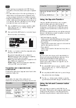
1

Press the MENU button to display the RX1 or RX2 
menu, and press the + or – button to display the 
AUTO SET screen.

2

Press and hold the SET button for 1 second or longer.

“YES” flashes on the display.

3

Press the SET button.

Clear Channel Scan starts searching for an available 
channel.
When Clear Channel Scan finishes, the channel with 
the least noise and interference will be set.
When the channel is set, infrared transmission starts 
automatically.


Some noise may occur when power is turned on. 
Accordingly, turn down the audio input level of 
devices connected to the unit when turning the power 
on.

4

Press and hold the SET button on the transmitter and 
press the POWER/MUTING button to turn the power 
on.

5

Place the infrared transmitter port on the unit near the 
infrared detector on the transmitter.

Information about the channel set on the unit is sent 
to the transmitter, and a prompt appears on the 
transmitter display asking if you want to change to 
that frequency.

6

Use the + or – button to select “YES,” then press the 
SET button on the transmitter.

This sets the transmit channel and compander mode.


• The infrared transmission from the unit in step 

3


continues for about 10 seconds. Perform steps 

4


and 

5

 within those 10 seconds. If 10 seconds have 

elapsed, you can reestablish the infrared link using 
the SYNC screen on the unit.

• Place the unit and transmitter within about 20 cm (8 

in.) of each other.

• If 5 seconds elapse without any user input after the 

prompt appears on the transmitter display, the 
transmitter returns to its previous state without 
changing the frequency.

• Communications using the infrared link may be 

adversely affected, depending on the surrounding 
environment. If this occurs, use the SYNC screen 
on the unit to reestablish the link.

Configuring the group/channel manually 
and configuring the channel settings via 
infrared communication (SYNC)

1

Configure the group/channel setting

(page 5)

2

Press the MENU button to display the RX1 or RX2 
menu, and press the + or – button to display the 
SYNC screen.

3

Press and hold the SET button for 1 second or longer.

A confirmation screen appears.

4

Use the + or – button to select “YES,” then press the 
SET button.

5

Press and hold the SET button on the transmitter and press 
the POWER/MUTING button to turn the power on.

6

Place the infrared transmitter port on the unit near the 
infrared detector on the transmitter.

Information about the channel set on the unit is sent 
to the transmitter, and a prompt appears on the 
transmitter display asking if you want to change to 
that frequency.

7

Use the + or – button to select “YES,” then press the 
SET button on the transmitter.

This sets the transmit channel and compander mode.

Note

Note

Notes

Summary of Contents for URX-S03D

Page 1: ...UHF Synthesized Diversity Tuner Operating Instructions URX S03D 4 590 341 11 1 2016 Sony Corporation ...

Page 2: ...nel Scan 6 Searching for Active Channels within a Group Active Channel Scan 6 Setting the Compander Mode 6 Using the Squelch Function 7 Using the Infrared Communication Function 7 Menu Displays and Detailed Settings 9 Menu Structure and Hierarchy 9 Basic Menu Operations 9 UTILITY Menu 9 RX tuner 1 2 Menu 10 Error Messages 11 Troubleshooting 12 Important Notes on Use 13 Usage and Storage 13 Cleanin...

Page 3: ...neously The true diversity system determines the stronger of the two antennas signals and selects it automatically achieving highly stable reception with minimal interruption and noise across a wide area Compatibility with Sony analog wireless microphones The built in DSP enables digital companding for high quality audio transmissions Switching to compander mode allows operation in conjunction wit...

Page 4: ...cts the displayed menu h SET button Changes the item to be set or enters the selected function or parameter value i or button Use to select a function or value j Infrared transmission port Transmits the frequency and compander mode settings configured on the unit to the transmitter k Display section A Audio input level meter Indicates the input signal level B Peak indicator Warns of excessive inpu...

Page 5: ...about the channel groups and channels that can be selected refer to the Frequency List on the CD ROM To prevent interference and noise beware of the following Do not use multiple transmitters that have been set to the same channel at the same time When using two or more channels at the same time always configure different channels within the same group Keep all transmitters and receivers at least ...

Page 6: ... to the CLR SCAN screen 4 Press the SET button when the desired channel number starts flashing The search for available channels finishes and the displayed channel is set Searching for Active Channels within a Group Active Channel Scan You can search for channels in use within the specified channel group This is useful when using more than one receiver in combination with a single transmitter Befo...

Page 7: ...searching for radio interference or external noise for example The following squelch functions are available on the unit However the functions can only be enabled or disabled together and not individually RF radio frequency squelch Audio output is muted if the RF input level drops below the RF squelch level The RF squelch level is fixed Tone squelch Audio output is muted unless radio waves that in...

Page 8: ...he unit in step 3 continues for about 10 seconds Perform steps 4 and 5 within those 10 seconds If 10 seconds have elapsed you can reestablish the infrared link using the SYNC screen on the unit Place the unit and transmitter within about 20 cm 8 in of each other If 5 seconds elapse without any user input after the prompt appears on the transmitter display the transmitter returns to its previous st...

Page 9: ... are not displayed UTILITY Menu The UTILITY menu includes items related to the basic receiver settings including meter displays These functions and parameters are explained here Underlined items are the factory setting The functions indicated by ADAPTER in the upper right corner are related to the AES EBU output when the receiver is used in conjunction with an optional wireless adapter The functio...

Page 10: ...hronization with an external word clock signal The current synchronization status is displayed UNLOCK or LOCK Terminating the sync signal 75ohm This function provides termination for the WORD SYNC connecter on the wireless adapter ON 75 ohm termination is added OFF 75 ohm termination is not added When the receiver is turned off the termination is released Displaying the accumulated running time TI...

Page 11: ... of the compander For details see Setting the Compander Mode page 6 Setting the frequency to an active channel ACT SCAN Search for channels already in use This is useful when using more than one receiver in combination with a single transmitter For details see Searching for Active Channels within a Group Active Channel Scan page 6 Setting the squelch function SQUELCH Enable the squelch function to...

Page 12: ...d on the supplied CD ROM and reconfigure the channel on each transmitter The transmitters are not set to the channels within the same channel group The channel plan is set so that no signal interference occurs when two or more transmitters are used simultaneously Set each transmitter to a different channel within the same channel group Adjacent channels are being used Use the channels separated by...

Page 13: ...Crystal controlled PLL synthesizer Receive frequencies Models available in USA 470 MHz to 542 MHz UC14 model 566 MHz to 608 MHz and 614 MHz to 638 MHz UC30 model 638 MHz to 698 MHz UC42 model Models available in Europe 470 MHz to 542 MHz CE21 model 566 MHz to 630 MHz CE33 model 638 MHz to 694 MHz CE42 model Model available in China 710 MHz to 782 MHz CN38 model Model available in Korea 925 MHz to ...

Page 14: ...E FOR DAMAGES OF ANY KIND INCLUDING BUT NOT LIMITED TO COMPENSATION OR REIMBURSEMENT ON ACCOUNT OF THE LOSS OF PRESENT OR PROSPECTIVE PROFITS DUE TO FAILURE OF THIS UNIT EITHER DURING THE WARRANTY PERIOD OR AFTER EXPIRATION OF THE WARRANTY OR FOR ANY OTHER REASON WHATSOEVER SONY WILL NOT BE LIABLE FOR CLAIMS OF ANY KIND MADE BY USERS OF THIS UNIT OR MADE BY THIRD PARTIES SONY WILL NOT BE LIABLE FO...

Page 15: ...Sony Corporation ...
Reviews: