background image

6

Caution

When you dispose of the unit or accessories, you must 
obey the law in the relative area or country and the 
regulation in the relative hospital.

Warning on power connection

Use a proper power cord for your local power supply.
1. Use the approved Power Cord (3-core mains lead) / 

Appliance Connector / Plug with earthing-contacts 
that conforms to the safety regulations of each 
country if applicable.

2. Use the Power Cord (3-core mains lead) / Appliance 

Connector / Plug conforming to the proper ratings 
(Voltage, Ampere).

If you have questions on the use of the above Power 
Cord / Appliance Connector / Plug, please consult a 
qualified service personnel.

Warning on power connection for 
medical use

Please use the following power supply cord.
With connectors (plug or female) and cord types other 
than those indicated in this table, use the power supply 
cord that is approved for use in your area.

*Note: Grounding reliability can only be achieved when the equip-
ment is connected to an equivalent receptacle marked ‘Hospital Only’ 
or ‘Hospital Grade’.

For the customers in Europe

This product has been manufactured by or on behalf of 
Sony Corporation, 1-7-1 Konan Minato-ku Tokyo, 108-
0075 Japan. Inquiries related to product compliance 
based on European Union legislation shall be addressed 
to the authorized representative, Sony Deutschland 
GmbH, Hedelfinger Strasse 61, 70327 Stuttgart, 
Germany. For any service or guarantee matters, please 
refer to the addresses provided in the separate service or 
guarantee documents.

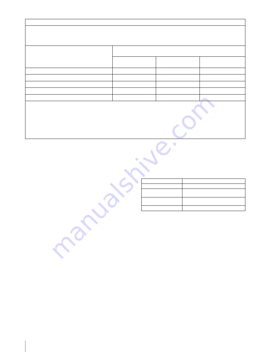
Recommended separation distances between portable and mobile RF communications equipment and the UP-D897

The UP-D897 is intended for use in an electromagnetic environment in which radiated RF disturbances are controlled. The 
customer or the user of the UP-D897 can help prevent electromagnetic interference by maintaining a minimum distance 
between portable and mobile RF communications equipment (Transmitters) and the UP-D897 as recommended below, 
according to the maximum output power of the communications equipment.

Rated maximum output power of transmitter 

W

Separation distance according to frequency of transmitter 

m

150 kHz to 80 MHz

d

 = 1.2

 √

P

80 MHz to 800 MHz

d

 = 1.2 

P

800 MHz to 2.5 GHz

d

 = 2.3 

P

0.01

0.12

0.12

0.23

0.1

0.38

0.38

0.73

1

1.2

1.2

2.3

10

3.8

3.8

7.3

100

12

12

23

For transmitters rated a maximum output power not listed above, the recommended separation distance 

d

 in meters (m) can 

be estimated using the equation applicable to the frequency of the transmitter, where 

P

 is the maximum output power rating 

of the transmitter in watts (W) according to the transmitter manufacturer.

NOTE 1: At 80 MHz and 800 MHz, the separation distance for the higher frequency range applies.

NOTE 2: These guidelines may not apply in all situations. Electromagnetic propagation is affected by absorption and 

reflection from structures, objects and people.

United States and Canada

Plug Type

HOSPITAL GRADE*

Cord Type

Min.Type SJT
Min.18 AWG

Minimum Rating for Plug 
and Appliance Couplers

10 A/125 V

Safety Approval

UL Listed and CSA

Summary of Contents for UP-D897

Page 1: ...2 345 260 15 1 Digital Graphic Printer 2005 Sony Corporation UP D897 Instructions for Use ...

Page 2: ...expressly approved in this manual could void your authority to operate this equipment All interface cables used to connect peripherals must be shielded in order to comply with the limits for a digital device pursuant to Subpart B of Part 15 of FCC Rules For the customers in Canada This unit has been certified according to Standard CAN CSA C22 2 No 60601 1 For the customers in the U S A and Canada ...

Page 3: ...se specified with the exception of replacement parts sold by Sony Corporation may result in increased emissions or decreased immunity of the UP D897 Warning If the UP D897 should be used adjacent to or stacked with other equipment it should be observed to verify normal operation in the configuration in which it will be used Guidance and manufacturer s declaration electromagnetic emissions The UP D...

Page 4: ...mode 2 kV common mode 1 kV differential mode 2 kV common mode Mains power quality should be that of a typical commercial or hospital environment Voltage dips short interruptions and voltage variations on power supply input lines IEC 61000 4 11 5 UT 95 dip in UT for 0 5 cycle 40 UT 60 dip in UT for 5 cycles 70 UT 30 dip in UT for 25 cycles 5 UT 95 dip in UT for 5 sec 5 UT 95 dip in UT for 0 5 cycle...

Page 5: ...transmitters as determined by an electromagnetic site survey a should be less than the compliance level in each frequency range b Interference may occur in the vicinity of equipment marked with following symbol NOTE 1 At 80 MHz and 800 MHz the higher frequency range applies NOTE 2 These guidelines may not apply in all situations Electromagnetic propagation is affected by absorption and reflection ...

Page 6: ...ease refer to the addresses provided in the separate service or guarantee documents Recommended separation distances between portable and mobile RF communications equipment and the UP D897 The UP D897 is intended for use in an electromagnetic environment in which radiated RF disturbances are controlled The customer or the user of the UP D897 can help prevent electromagnetic interference by maintai...

Page 7: ...the Menu 12 Menu Flow 12 Menu List 13 Basic Menu Operations 14 Registering Menu Settings 16 Printing the Menu List 16 Printing 17 Starting a Print Job 17 Cancelling a Print Job 17 Making Copies of the Last Printout 17 Feeding Paper 17 Adjusting the Contrast and Brightness 18 Others Precautions 19 On Safety 19 On the Printer Carriage 19 On Installation 19 Maintenance 20 Cleaning the Cabinet 20 Clea...

Page 8: ...settings Easy Paper Loading Free access to the door panel allows you to drop paper into the unit for easy loading Location and Function of Parts and Controls For more details see the referenced page numbers enclosed in parentheses Front Panel A Power ON OFF Switch 10 14 17 20 Press to switch to ON to turn the power on The back light on the LCD lights in green B Printer window display LCD liquid cr...

Page 9: ...ower connection for medical use on page 6 Connections After connecting the USB connecting cable supplied to the unit and the computer connect the power cord For details about the unit connection refer to the manuals for the computer or other peripheral devices Notes Before connecting the unit to the computer turn off the unit computer monitor and all peripheral devices connected to the computer Be...

Page 10: ... between sheets of paper that contain no plastic Do not store printouts where they will be exposed to direct sunlight or high humidity Do not store printouts near volatile liquids or allow the prints to contact any organic volatile liquid cellophane tape or any compound of vinyl chloride To prevent fading do not stack printouts on or under a diazo copy sheet To mount printouts on another sheet of ...

Page 11: ...Paper exposed to dirt or dust cannot be used for printing 4 Close the paper door and press on it to shut it Notes Make sure that the paper is loaded straight If it is skewed this could cause the paper to jam If you did not pull out enough paper in step 3 press the FEED button on the operation panel to feed some more paper out of the unit without pulling out the paper Remove label and pull out 15 t...

Page 12: ...ents are retained even if the unit is turned off You can set up the unit according to its intended purpose connected equipments or your individual preferences You can store up to three settings as a set of user settings Menu Flow The contents displayed on the LCD changes in sequence as you turn the jog dial as shown in the following menu flow chart and you can make the settings for each menu item ...

Page 13: ... extra blank paper between prints BACK Cancels the setting change and returns to the item selection column GAMMA b When ME S is selected in MEDIA GAMMA is fixed to TONE 1 To select the tone density gradation GA 4 TONE 4 Softest gradation GA 3 TONE 3 Hard gradation GA 2 TONE 2 Standard GA 1 TONE 1 Soft gradation BACK Cancels the setting change and returns to the item selection column IMAGE To set t...

Page 14: ...ngs as No 2 SA 1 Registers the menu settings as No 1 BACK Cancels the setting change and returns to the item selection column SHARP b To adjust the sharpness of the printout You can set the sharpness to any of 15 steps from 0 to 14 At a setting of 0 the outline of the printout is not emphasized A setting of step 2 is the factory setting BACK Cancels the setting change and returns to the item selec...
Page 15: ...p or down 4 Press the jog dial The unit enters the mode in which you can select the printing direction DI NOR which is the factory setting is displayed on the LCD DI NOR is the currently selected setting In this menu operation you will change the setting to DI REV 5 Display DI REV in the LCD by turning the jog dial up or down and then press the jog dial DI REV is registered as the printing directi...

Page 16: ... the loaded settings 1 Confirm that READY is displayed on the LCD and press the jog dial 2 Display LOAD by turning the jog dial and then press the jog dial again 3 Display the number corresponding to the desired settings and then press the jog dial Settings corresponding to the number selected in step 3 are loaded When you change the loaded settings The unit operates according to the changed setti...

Page 17: ... In the following figure the currently selected paper is the UPP 110S paper Cancelling a Print Job To cancel a print job in progress press the OPEN button or the FEED button Making Copies of the Last Printout Press the COPY button The unit makes a copy of the last printout The image of the last printout is retained in the unit s memory until you make a printout of another image or turn the power o...

Page 18: ... adjusting function is equivalent to Light of the density control provided with the printer driver The value adjusted by using this CONTR control is added to the value already set as Light To adjust the brightness You can adjust the brightness of printouts using the BRIGHT control To make the image brighter Turn the BRIGHT control clockwise To make the image darker Turn the BRIGHT control counterc...

Page 19: ...e the unit on a level and stable surface If you use the unit with placed on an uneven surface malfunction of the unit is likely to occur Do not install the unit near heat sources Avoid locations near radiators or air ducts or places subject to direct sunlight or excessive dust humidity mechanical shock or vibration Provide adequate air circulation to prevent heat build up Do not place the unit on ...

Page 20: ...N OFF switch to ON to turn the unit on 2 Press the OPEN button to open the door If the paper is loaded in the paper tray remove it 3 Insert the cleaning sheet with the black surface facing down into the groove of the paper tray 4 Close the door by pushing it 5 Press the jog dial The menu item changed last is displayed 6 Display CLEAN by turning the jog dial and then press the jog dial 7 Confirm th...

Page 21: ...oistened with ethyl alcohol Notes After the surface of the platen roller wiped has been dried completely turn the platen roller to clean another portion Do not turn the platen roller with hands Use the FEED button to turn it To clean another part of the surface of the platen roller go to the next step 4 Press and hold down the FEED button so that the platen roller turns automatically Release the F...

Page 22: ...Media label 1 USB cable 1 824 211 41 Sony 1 Before Using this Printer 1 Service Contact List 1 Software License Agreement 1 Medical Specifications Protection against electric shock Class I Protection against harmful ingress of water Ordinary Degree of safety in the presence of a flammable anesthetic mixture with air or with oxygen or nitrous oxide Not suitable for use in the presence of a flammabl...

Page 23: ...nsation may have formed inside the unit Switch the unit off and let it set for 1 2 hours until it warms to room temperature then try printing again Printouts dirty Thermal head dirty tUse the head cleaning sheet provided with the unit to clean the thermal head page 20 Platen roller dirty tClean the platen roller using a soft cloth moistened with ethyl alcohol page 21 The unit stops printing while ...

Page 24: ...asic operations 14 list 13 loading the menu settings 16 menu flow 12 printing the menu list 16 storing the menu settings 16 O Overview 8 P Paper feeding 17 loading 10 notes on storing and handling 10 paper you can use 10 Precautions on installation 19 paper cutter 19 printer carriage 19 safety 19 Printer driver 9 Printing adjusting the brightness 18 adjusting the contrast 18 cancelling 17 staring ...

Page 25: ...Sony Corporation ...

Reviews: