


8
Using Your New TV
Notes
• If your DVD player can output interlace and progressive mode signals, select
the interlace output when connecting to
(component video input) on your
TV. Your TV can receive either 525i/60Hz or 625i/50Hz interlace signals.
• Some DVD player terminals may be labeled differently:
• Since the high quality pictures on a DVD disc contain a lot of information,
picture noise may appear. In this case, adjust the sharpness (“SHARP”) in the
“ADJUST” menu of the “PICTURE MODE” menu (see page 24).
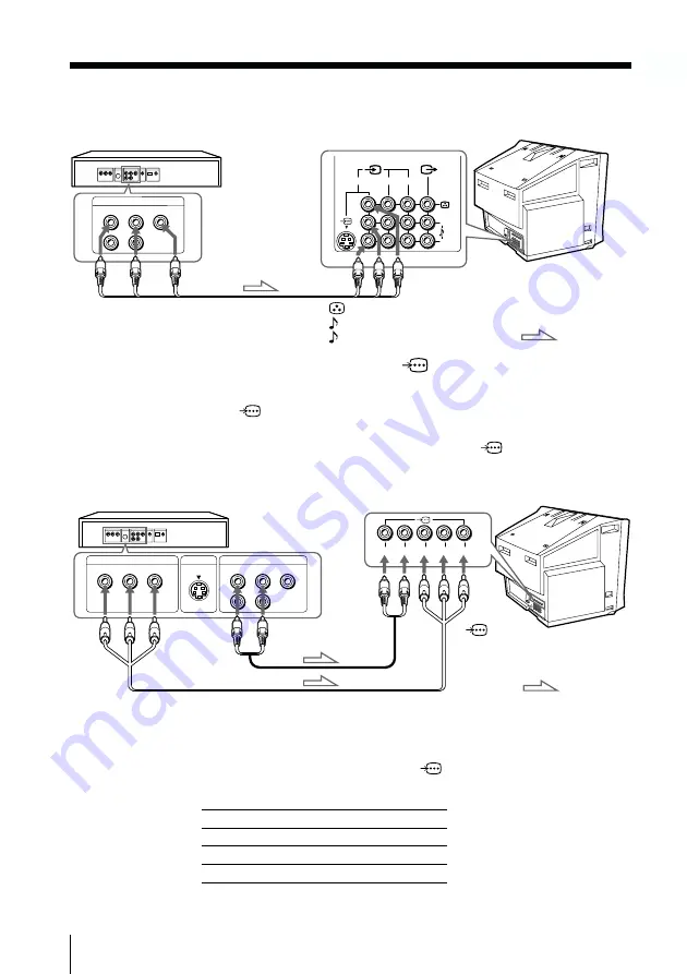
Connecting a DVD player using the
(component
video input) jacks
1 Connect R and L under
(component video input) on your TV to the LINE OUT,
AUDIO R and L output connectors on your DVD player.
2 Using a component video cable, connect Y, C
B
, and C
R
under
(component video
input) on your TV to the COMPONENT VIDEO OUT Y, C
B
, and C
R
output
connectors on your DVD player.
DVD player
To
L (white)
R (red)
Audio cable
(not supplied)
To component
video output
Component video cable
(not supplied)
To audio
output
: Signal flow
To
(component
video input)
Connect
To (on the DVD player)
Y (green)
Y
C
B
(blue)
C
b
, B-Y or P
B
C
R
(red)
C
r
, R-Y or P
R
VIDEO
R-AUDIO-L
LINE OUT
Y
COMPONENT VIDEO OUT
S VIDEO OUT
C
B
C
R
R
L
Y
C
B
C
R
Rear of TV
Connecting a DVD player using the
t
(video input) jacks
VIDEO
R-AUDIO-L
LINE OUT
1
2
3
L(MONO)
R
DVD player
Audio/Video cable
(not supplied)
(yellow)
-L (MONO) (white)
-R (red)
To
t
1, 2, or 3
(video input)
: Signal flow
Rear of TV
Connecting optionals components (continued)


