background image

— 16 —

KV-32FV27 / 36FS13 / 36FS17 / 36FV27 / 38FS17 

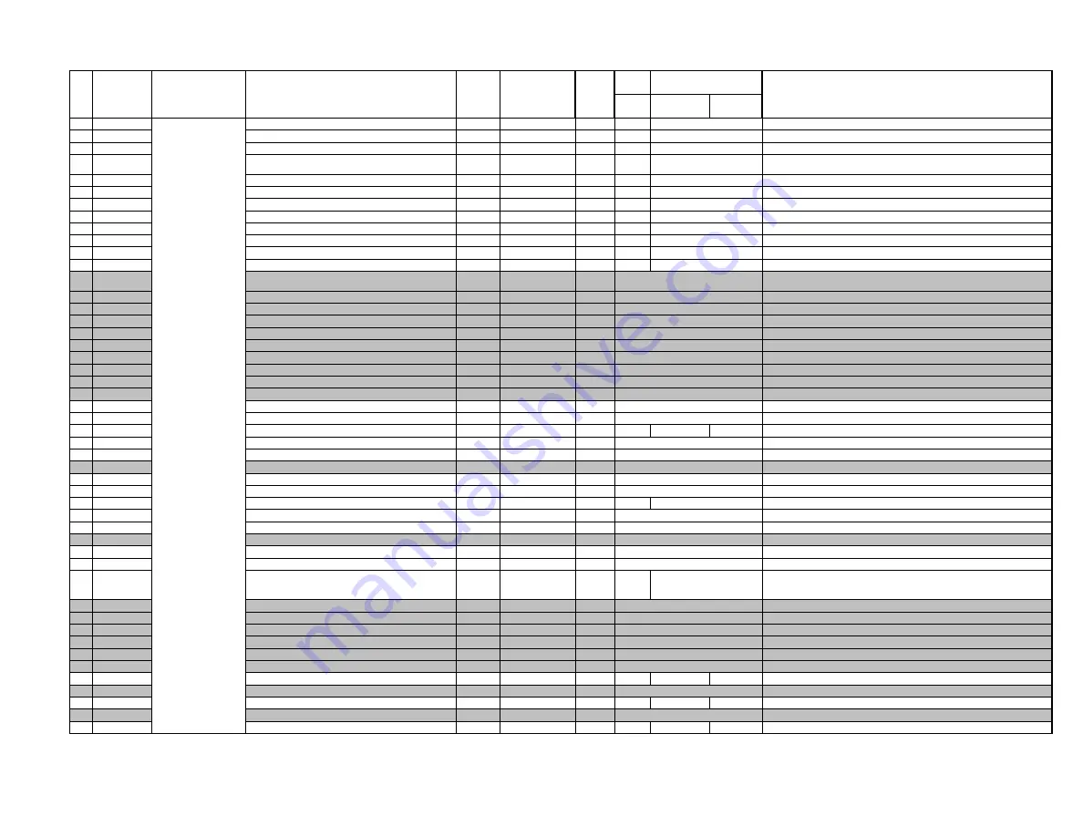
4-4. ADJUSTMENT ITEMS (1 OF 6)

Description 

Data 

Adj/Fix 

Initial 

32" 

36"/38"                                               Comments

Range

Data

FV

FS

FV

0

HPOS

H-Position

0-63

Adj

7

7

7

0:  2ms delay,  63:  2ms advance

1

HSIZ

H-Size

0-63

Adj

1010

10

EW DC bias, 0:  -0.5V,  31:  0V,  63:  +0.5V

2

VBOW

AFC Bow

0-15

Adj

6

6

6

0: top/bottom delay 900ns,  7: center,  15: top/bottom advance 900ns

3

VANG

AFC Angle

0-15

Adj

5

5

5

0: top delay/bottom advance 650ns,  7: center,  
15: top advance/bottom delay 650ns

4

TRAP

Trapezium Adjustment

0-15

Adj

6

6

6

0: 1.5ms advance,  15: 1.5ms delay

5

PAMP

Pin Compensation

0-63

Adj

32

32

32

0: 0.15Vpp,  31: 0.7Vpp,  63: 1.3Vpp

6

UCPN

Upper Corner Pin

0-63

Adj

36

36

36

0:  -0.4V,  63: +0.4V

7

LCPN

Lower Corner Pin

0-63

Adj

36

36

36

0:  -0.4V,  63: +0.4V

8

VSIZ

V-Size

0-63

Adj

0

0

0

0: -15%,  31: 0%,  63: +15%

9

VPOS

V-Position

0-63

Adj

31

31

31

0: -0.1V,  31: 0V,  63: +0.1V

10

VLIN

V-Linearity

0-15

Adj

7

7

7

0: 85% top enlarged,  7: 100% top normal,  15:  115% top compressed

11

VSCO

S-Correction

0-15

Adj

7

7

7

0: 0V added to VD,  15:  100mVpp added to VD

12

VZOM

16:9 CRT Zoom Mode On/Off

0,1

FIX

00

0: Zoom Off,  1: Zoom On 
(top/bottom cut by 25% when ASPECT=31, RGB blanked in this interval)

13

EHT

Vertical Size High Voltage Correction

0-15

FIX

4

4

0:  Picture adjusted 0%,  15:  Picture Adjusted -5%

14

ASP

Aspect Ration Control 4:3 Mode

0-63

FIX

47

47

0: 75%(16x9 CRT Full),  31: 100%(4x3 CRT Full),  63: 110%

15

ASP1

Aspect Ration Control 16:9 Mode

0-63

FIX

47

47

0: 75%(16x9 CRT Full),  31: 100%(4x3 CRT Full),  63: 110%

16

SCRL

16:9 Vertical Scroll During Zoom

0-63

FIX

31

31

0: Scrolled toward top 32H,  63: Scrolled toward bottom 32H

17

HBSW

H Blanking Switch

0,1

FIX

1

1

0:  OFF,  1: ON 

18

LBLK

Left Blanking

0-15

FIX

15

15

0: +1.2ms,  7: Center,  15: -1.2ms

19

RBLK

Right Blanking

0-15

FIX

00

0: +1.2ms,  7: Center,  15: -1.2ms

20

HDW

H Drive Pulse Width

0,1

FIX

1

1

0: Normal Mode (25ms),  1: Narrow Pulse Width

21

EWDC

EW/DC Display 4x3 on 16x9 CRT

0,1

FIX

00

0:  OFF,  1: ON 

22

LVLN

Picture Bottom Lin Adjust

0-15

Adj

0

0

0: 100%,  15: 85% Picture top compressed

23

UVLN

Picture Top Lin Adjust

0-15

Adj

0

0

0: 100%,  15: 85% Picture bottom compressed

24

RDRV

Red Drive

0-63

Adj

31

31

48

54

0:  1.5Vpp, 63: 3.0Vpp Red Signal Output

25

GDRV

Green Drive

0-63

Adj

31

31

0:  1.5Vpp, 63: 3.0Vpp Greem Signal Output

26

BDRV

Blue Drive

0-63

Adj

31

31

0:  1.5Vpp, 63: 3.0Vpp Blue Signal Output

27

RCUT

Red Cutoff

0-15

FIX

7

14

0: 3.5mA IK,  7: 13mA IK,  15: 22.7mA IK

28

GCUT

Green Cutoff

0-15

Adj

7

7

0: 3.5mA IK,  7: 13mA IK,  15: 22.7mA IK

29

BCUT

Blue Cutoff

0-15

Adj

7

7

0: 3.5mA IK,  7: 13mA IK,  15: 22.7mA IK

30

RDR4

Video 4 Red Drive

0-63

Adj

31

31

54

0:  1.5Vpp, 63: 3.0Vpp Red Signal Output

31

GDR4

Video 4 Green Drive

0-63

Adj

31

31

0:  1.5Vpp, 63: 3.0Vpp Greem Signal Output

32

BDR4

Video 4 Blue Drive

0-63

Adj

31

31

0:  1.5Vpp, 63: 3.0Vpp Blue Signal Output

33

RCU4

Video 4 Red Cutoff

0-15

FIX

7

14

0: 3.5mA IK,  7: 13mA IK,  15: 22.7mA IK

34

GCU4

Video 4 Green Cutoff

0-15

Adj

7

7

0: 3.5mA IK,  7: 13mA IK,  15: 22.7mA IK

35

BCU4

Video 4 Blue Cutoff

0-15

Adj

7

7

0: 3.5mA IK,  7: 13mA IK,  15: 22.7mA IK

36

SBRT

Sub Brightness

0-31

Adj

15

adjust to

IRE 

cutoff

adjust to IRE cutoff

Sub Brightness

37

RON

Red Off

0,1

FIX

1

1

0:OFF, 1:ON

38

GON

Green Off

0,1

FIX

1

1

0:OFF, 1:ON

39

BON

Blue Off

0,1

FIX

1

1

0:OFF, 1:ON

40

AXPL

Axis PAL

0,1

FIX

00

0: Normal Axis,  1: Forced PAL Asix

41

CBPF

Chroma BPF On/Off

0,1

FIX

1

1

0: BPF OFF,  1:  BPF ON

42

COFF

Color On/Off

0,1

FIX

00

0:  Chroma OFF,  1: Chroma ON

43

TSSP

Sub Sharpness for TV Input

0-15

Fix by model

6

6

5

6

0=-12dB,  7=+3.5dB,  15=+9dB

44

TSPF

Sharpness fo for TV Input

0,1

FIX

1

1

0=2.5MHZ,  1=3.0MHz

45

VSSP

Sub Sharpness for Video Input

0-15

Fix by model

7

7

5

7

0=-12dB,  7=+3.5dB,  15=+9dB

46

VSPF

Sharpness fo for Video Input

0,1

FIX

1

1

0=2.5MHZ,  1=3.0MHz

47

YSSP

Sub Sharpness for YUV Input

0-15

Fix by model

7

7

6

7

0=-12dB,  7=+3.5dB,  15=+9dB

Register

Name

VP

CXA2131AS 

Summary of Contents for TRINITRON KV-32FV27

Page 1: ...C S45GA KV 36FS13 RM Y180 US SCC S44HA KV 36FS13 RM Y180 CND SCC S45EA KV 36FS13H RM Y180 HAWAII SCC S46FA KV 36FS17 RM Y181 US SCC S44GA KV 36FS17H RM Y181 HAWAII SCC S46EA KV 36FV27 RM Y182 US SCC S44JA KV 36FV27 RM Y182 CND SCC S45FA KV 36FV27H RM Y182 HAWAII SCC S46GA KV 38FS17 RM Y181 E SCC S50EA SelfDiagnosis Supported model RM Y182 9 965 901 01 KV 36FV27 ...

Page 2: ...G then ENTER to write into memory SERVICE ADJUSTMENT MODE MEMORY Disp Item Item data SERVICE 0 VP HSIZ 7 TV Item order Green Red MUTING ENTER 7 Press 8 then ENTER on the Remote Commander to initialize Disp Item Item data WRITE 0 VP HSIZ 7 TV Item order Carry out step 7 when adjusting IDs 0 to 7 and when replacing and adjusting IC002 8 DO NOT turn off set until SERVICE appears SECTION 4 CIRCUIT ADJ...

Page 3: ... 0 Normal Mode 25ms 1 Narrow Pulse Width 21 EWDC EW DC Display 4x3 on 16x9 CRT 0 1 FIX 0 0 0 OFF 1 ON 22 LVLN Picture Bottom Lin Adjust 0 15 Adj 0 0 0 100 15 85 Picture top compressed 23 UVLN Picture Top Lin Adjust 0 15 Adj 0 0 0 100 15 85 Picture bottom compressed 24 RDRV Red Drive 0 63 Adj 31 31 48 54 0 1 5Vpp 63 3 0Vpp Red Signal Output 25 GDRV Green Drive 0 63 Adj 31 31 0 1 5Vpp 63 3 0Vpp Gree...

Page 4: ...FIX 0 0 0 0dB 63 31db 1dB steps 2 INPA Input Attenuation 0 127 FIX 3 3 0 0dB 127 31 5dB 0 5dB steps 0 COUT Chroma Signal Gain BPF 0 3 FIX 3 3 Input Output gain 1 BPF ON 1 YAPS Y V Compensation Peaking 0 3 FIX 3 3 Correctin enabled for digital analog inputs 2 NSDS Standard Non Standard Processing 0 3 FIX 0 0 Standard adaptive processing 3 MSS Inter frame Inter line Mode 0 3 FIX 0 0 Adaptive Process...

Page 5: ...ection Test Bit 0 1 FIX 0 0 Normal Mode 45 CSHD H V counter Test Bit 0 1 FIX 0 0 Normal Mode 46 KCTT H V counter Test Bit 0 3 FIX 0 0 Normal Mode 47 SHT Non Standard Detection Test Bits 0 1 FIX 0 0 Normal Mode 48 VCT H V counter Test Bit 0 1 FIX 0 0 Normal Mode 49 OTT H V counter Test Bit 0 1 FIX 0 0 Normal Mode 50 CL2D Clock Generator Test Bit 0 1 FIX 1 1 Normal Mode 51 CGGT Clock Generator Test ...

Page 6: ...2 1 2ms 3 1 5ms 16 CLMS Clamp Pulse Start 0 3 FIX 2 2 0 1 0ms 1 1 5ms 2 2 0ms 3 2 5ms 17 LMOF Luminance Offset 0 3 FIX 3 3 0 NO OFFSET 1 16LSB 2 8LSB 3 16LSB 18 PYDL Y C Delay 0 15 FIX 8 2 0 8 pixels 15 7 pixels 19 FRMY Frame Y Level 0 15 Fix by Model 6 4 5 Adjusts 4 MSB of Frame Y Signal 20 FRSL Frame Type Select 0 1 FIX 1 1 0 Normal frame 1 3D frame 21 FRWH Frame Width Horizontal 0 7 FIX 4 4 0 N...

Page 7: ...0 Search for ID 1 data one line in VBI 0 DUM1 CCD Dummy Register Used to display CC data in Service Mode 1 VOSD VChip OSD Test Register 0 1 FIX 0 0 Used to display VChip data in Service Mode 0 DISP OSD Position 0 63 Adj 15 15 OSD horizontal position 1 RAMW OSD RAM Window 0 1 FIX 0 0 2 ICMP OSD Non interlace Threshold 0 15 FIX 4 4 0 0 fields 15 15 fields 3 IPOR OSD Non interlace Even Odd Display 0 ...

Page 8: ...n Drive MOVIE GDRV GDR4 GDOF 2 BDOF Blue Drive offset for WARM 0 63 FIX 15 15 Blue Drive MOVIE BDRV BDR4 BDOF 3 RCOF Red Cutoff offset for WARM 0 31 FIX 0 0 Red Cutoff MOVIE RCUT RCU4 RCOF 4 GCOF Green Cutoff offset for WARM 0 31 FIX 2 2 GREEN Cutoff MOVIE GCUT GCU4 GCOF 5 BCOF Blue Cutoff offset for WARM 0 31 FIX 7 7 BLUE Cutoff MOVIE BCUT BCU4 BCOF 6 DCOF Dynamic Color setting for WARM 0 1 FIX 0...

Page 9: ...UB BRIGHT ADJUSTMENT SBRT 1 Set to Service Adjustment Mode 2 Input a gray scale pattern signal 3 Set the PICTURE to minimum and BRIGHT to normal 4 Select SBRT with 1 and 4 5 Adjust SUB BRIGHT level with 3 and 5 so that the stripe second from the right is faintly visible 6 Write into the memory by pressing MUTING then ENTER white black second from the right SUB HUE SUB COLOR ADJUSTMENT T2HU T2CO V2...

Page 10: ...nal 2 Set to Service Adjustment Mode 3 Select VLIN VSCO PAMP and PPHA with 1 and 4 4 Adjust with 3 and 6 for the best picture 5 Write the memory by pressing MUTING then ENTER V LINEARITY VLIN VS CORRECTION VSCO PIN AMP PAMP PIN PHASE PPHA V ANGLE VANG V BOW VBOW UPPER PIN UPIN AND LOW PIN LPIN ADJUSTMENTS 1 Input a monoscope signal 2 Set to Service Adjustment Mode 3 Select VANG VBOW UPIN and LPIN ...

Page 11: ... Confirm that number 0 color changes to red 5 Push on the Remote Confirm that the number increases up to 5 and the picture rotates clockwise 6 Push on the Remote Confirm that the number decreases down to 5 and the picture rotates counter clockwise 7 Push on the Remote Return the value to 0 SET UP Channel Set up Favorite Channel Video Label Language English Tilt Correction Menu 5 0 5 ...

Reviews: