background image

KV-21FT250

KV-21FT250 

18


Purse lock dia.5

FBT 

(G2)

FBT 


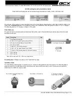
Dress Earth Assy, Coating, Lead Assy, G2 & Focus with purse lock Purse Lock Ø5. as shown
Note : Keep Lead Assy, G2 away from HV Cable (min 1mm/kV)

Ensure Lead Assy, G2 is kept away from heat sinks

(Focus)

ECA

CN704(C) CN705(C) CRT

SOCKET

Lead Assy, Focus

Lead Assy, G2

Purse Lock, dia.5

Figure b

Conn. Assy, 5P

Lead Assy,
Focus

Earth Assy,
Coating

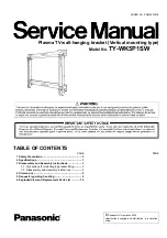
Rear view of Lead Assy, Focus & G2,

Lead Assy,
G2

Use this as a reference to dress
ECA, Lead Assy, Focus & G2.

Dress tight at the portion to avoid
wire touches rear cover .

Keep Lead Assy, G2

away from Heat

Keep Lead Assy,

G2

away from HV

TVSR Requirement :

1. Spacing between HV cable and other conductive part’s surface is
1mm/kV or more.
2. Spacing between HV cable's and enclosure with ventilation or the edge
where terminal bracket and rear cover meet: 10 mm or more.

CAUTION:

Do not overpull the wires during dressing --> avoid disconnection 
of wire.

Figure a

Figure c

Figure d

Safety

Operation

2-10. FBT  WIRE  DRESSING

Summary of Contents for Trinitron KV-21FT250

Page 1: ... 9 883 762 02 KV 21FT250 RM YA005 LATIN NORTH SCC S85A A HISTORY INFORMATION FOR THE FOLLOWING MANUAL ORIGINAL MANUAL ISSUE DATE 8 2007 UPDATED ITEM REVISION DATE SUBJECT 8 2007 No revisions or updates are applicable at this time 5 2008 Added new PN for IC IC001 New PN includes software data Replaced pg 60 ...

Page 2: ...TRON COLOR TELEVISION SERVICE MANUAL BX 1SCHASSIS MODEL NAME REMOTE COMMANDER DESTINATION CHASSIS NO 9 883 762 02 KV 21FT250 RM YA005 LATIN NORTH SCC S85A A SelfDiagnosis Supported model KV 21FT250 RM YA005 ...

Page 3: ...0 3 2 Convergence Adjustment 21 3 3 Focus Adjustment 22 3 4 G2 Screen Adjustment 23 SECTION 4 CIRCUIT ADJUSTMENTS 24 4 1 Remote Adjustment Buttons and Indicators 24 4 2 Accessing the Service Menu Mode 25 4 3 Confirming Service Adjustment Changes 26 4 4 White Balance Adjustments 26 4 5 Picture Quality Adjustments 26 4 6 Service Data 28 SECTION 5 DIAGRAMS 43 5 1 Circuit Boards Location 43 5 2 Printed...

Page 4: ...ion is the maximum wattage Design and specifications are subject to change without notice Trademarks and Copyrights Sony FD Trinitron WEGA Steady Sound and Intelligent Picture are registered trademarks of Sony Corporation As an ENERGY STAR Partner Sony Corporation has determined that this product meets the ENERGY STAR guidelines for energy efficiency ENERGY STAR is a U S registered mark KV 21FT250 ...

Page 5: ... this receiver is directly connected to the AC power line SAFETY RELATED COMPONENT WARNING Components identified by shading and mark on the schematic diagrams exploded views and in the parts list are critical for safe operation Replace these components with Sony parts whose part numbers appear as shown in this manual or in supplements published by Sony Circuit adjustments that are critical for safe...

Page 6: ...l part having a return to chassis must not exceed 0 5 mA 500 microamperes Leakage current can be measured by any one of three methods 1 A commercial leakage tester such as the Simpson 229 or RCA WT 540A Follow the manufacturers instructions to use these instructions 2 A battery operated AC milliampmeter The Data Precision 245 digital multimeter is suitable for this job 3 Measuring the voltage drop...

Page 7: ... used to review the failure occurrence data stored in memory to reveal past problems and how often these problems occur 1 Diagnostic Test Indicators When an error occurs the STANDBY LED indicator will flash a set number of times to indicate the possible cause of the problem If there is more than one error the indicator will identify the first of the problem areas Results for all of the following dia...

Page 8: ...yed as shown below Channel 8 0 Quitting the Self Diagnostic Screen To quit the entire self diagnostic screen turn off the power switch on the Remote Commander or the main unit Self Diagnostic Circuit A BOARD IC001 Y CHROMA JUNGLE A BOARD IC804 V OUT A BOARD IC001 SYSTEM A BOARD IC003 MEMORY IK FROM C BOARD IC751 PIN 5 EHTO FROM A BOARD Q816 COLLECTOR 32 RED LED F B PLS V GUARD SDAO SDA DISPLAY 84 ...

Page 9: ...emove 8 screws from Rear Cover BVTP 4 X 16 TYPE2 IT 3 2 Remove 1 screw from terminal bracket on Rear Cover BVTP 4 X 16 TYPE2 IT 3 3 Slide to remove Rear Cover from Beznet 1 Remove 2 screws from Tweeter BVTP 3 X 12 TYPE2 TT B 2 Remove 2 screws from Speaker PWTP2 4 X 16 9 screws Rear cover 1 1 screw 2 3 1 2 ...

Page 10: ...ard 1 2 1 4 3 5 1 Remove AC cord from holder on bottom cover 2 Disconnect H3 Board connector from CN005 on the A Board 3 Release claw and slide out A Board 4 Disconnect speaker wire from CN200 on the A Board 5 Slide to move A Board 1 3 CHASSIS ASSEMBLY REMOVAL ...

Page 11: ...s built into the rubber 3 Do not force turn the foot of the rubber cover This may cause the shatter hook terminal to protrude and damage the rubber Turn up one side of the rubber cap in the direction indicated by arrow a Use your thumb to pull the rubber cap firmly in the direction indicated by arrow b When one side of the rubber cap separates from the anode button the anode cap can be removed by t...

Page 12: ...wire P N 1 923 082 52 CAUTION Prevent tie cable from touching rear cover or any enclosures by turning them away from it avoid rattle sound Also prevent tie cable s end from touching solder side of board Dress UL Wire 1 923 082 52 according to Figure 1 b as shown Note Ensure UL wire does not touch high temperature resistors R828 R829 R889 Ensure UL wire does not touch high temperature resistors R82...

Page 13: ...or R121 Lead Assy Jumper Conn Assy 5P YUV Pin Wire A021 Figure 5 Figure 5 a Figure 5 b Shield case Shield case C M for OSD drift from RF to no signal Make sure the Connector Assy 5P YUV is press down towards the board 1 Dress Conn Assy 5P YUV Lead Assy Jumper with Pin Wire A021 as shown 2 Dress Lead Assy Jumper according to the route shown in the Figure Note Ensure Lead Assy Jumper is dress away f...

Page 14: ...tation Coil A Conn Assy 7P B Lead Assy Earth C UL Wire 1 923 000 81 D Rotational Coil Conn A Conn Assy 7P B Lead Assy Earth C UL Wire 1 923 000 81 Non Rotational Coil Models Rotational Coil Dress Conn Assy 7P UL Wire 1 923 000 81 and Lead Assy with purse lock Ø5 as shown Dress Conn Assy 7P UL Wire 1 923 000 81 Lead Assy Earth and Rotational Coil Conn with purse lock Ø5 as shown Non Rotational Coil...

Page 15: ...e lock and lock the standing purse lock Note 1 AC Power Cord Lead Assy Earth and Lead Assy Speaker Right already inserted into standing purse lock during Chassis Assy 2 Keep bunch of wires above of RY600 to avoid wires from being sandwiched with front jack and pushed against relay 3 Dress wires away from beznet s front terminal to prevent wires from being sandwiched when docking 4 Dress speaker wi...

Page 16: ...nsert Lead Assy Speaker Left followed by AC Power Cord into CRT support s hook Note Ensure wires do not come out from hook Keep wires away from heat sink and other high temperature parts 2 Make sure Front Control wire lie flat on bottom cover and dressed around AC Power Cord Note Keep Front Control Wire away from heat sinks and other high temperature parts 3 Ensure Tweeter s tab is facing inside t...

Page 17: ... Conn Assy 5P DY Conn goes above Conn Assy 5P DY Conn goes underneath of Earth Assy Coating and Conn Assy 5P Make sure DY Conn is on the right side of Earth Assy Purse Lock Ø5 10mm Use heat sink height to estimate purse lock location Dress DY Conn and Conn Assy 5P 200V with Purse Lock Ø5 TVSR Requirement All wires must be kept away from FBT area by a distance of 10mm or more CAUTION Do not overpul...

Page 18: ...w of Lead Assy Focus G2 Lead Assy G2 Use this as a reference to dress ECA Lead Assy Focus G2 Dress tight at the portion to avoid wire touches rear cover Keep Lead Assy G2 away from Heat Keep Lead Assy G2 away from HV TVSR Requirement 1 Spacing between HV cable and other conductive part s surface is 1mm kV or more 2 Spacing between HV cable s and enclosure with ventilation or the edge where termina...

Page 19: ... Spacing between HV cable and other conductive part s surface is 1mm kV or more 2 Spacing between HV cable s and enclosure with ventilation or the edge where terminal bracket and rear cover meet 10 mm or more 3 Spacing between edge of anode cap and conductive parts is 0 5mm kV or more CAUTION Do not overpull the wires during dressing avoid disconnection of wires Gate 2 positions of HV Safety Opera...

Page 20: ...st or west Adjustment Procedure 1 Input a raster signal with the pattern generator 2 Loosen the deflection yoke mounting screw and set the purity control to the center as shown below Purity control 3 Turn the raster signal of the pattern generator to green 4 Move the deflection yoke backward and adjust with the purity control so that green is in the center and red and blue are even on both sides Red...

Page 21: ... R G B R G B 4 pole magnet RV750 H STAT C Board 2 Tilt the 4 pole magnet and adjust static convergence to open or close the 4 pole magnet When the 4 pole magnet is moved in the direction of arrow A and B the red green and blue dots move as shown below Moved RV750 H STAT R R G G B B A B B A B R G G R B Horizontal Static Convergence Adjustment If the blue dot does not converge with the red and green...

Page 22: ...een Corner Convergence Adjustment Affix a Piece A 90 Convergence Correct Permaloy Assy Correction to the misconverged areas b a c d a d screen corner misconvergence a1 b1 c1 d1 a1 d1 Piece A 90 Convergence Correct or Permaloy Assy Correction 3 3 FOCUS ADJUSTMENT FOCUS adjustment should be completed before White Balance adjustment See 4 4 White Balance Adjustment 1 Receive digital monoscope pattern ...

Page 23: ...nd Brightness to STANDARD Set TV to Video mode Set WHBL 016 RGBB to 01 2 Connect R G B of the C Board cathode to oscilloscope 3 Adjust Brightness to obtain the cathode value to the value shown below 170 2Vdct 4 Adjust SCREEN VR on the FBT until the scanning line disappears 5 Set WHBL 16 RGBB back to 00 ...

Page 24: ...se Data value 1 Display next Item 2 Display next Category 4 Display previous Item DISPLAY Service Mode POWER Service Mode VOLUME Service Mode RM YA005 SECTION 4 CIRCUIT ADJUSTMENTS Electrical Adjustments by Remote Commander Use the Remote Commander RM YA005 to perform the circuit adjustments in this section Test Equipment Required 1 Pattern generator 2 Frequency counter 3 Digital multimeter 4 Audi...

Page 25: ... STR31 7 11U 0011 1111 FF FF 00084 Status Byte Status Byte Flash DCXO 1 SSD 2 SSD 000 00 00 0000 3E 40 000 004000 0000FF 1 On the Remote Commander press 2 to select the next category or 5 to select the previous category 2 Press 1 to select the next item or 4 to select the previous item 3 Press 3 to increase the data value or 6 to decrease the data value 4 Press MUTING then 0 to write into memory G...

Page 26: ...de and write PMAX data 8 steps for models with V Compression features only 9 Press MUTING then 0 to write into memory 10 Set PWL and BLBG back to initial data PWL 01h and BLBG 00h 11 Press MUTING then 0 to write into memory Sub Color Adjustment 1 Set TV to Video mode 2 Set Picture mode to CUSTOM 3 Input PAL 100 Color Bar CB to TV set OTHER MODEL 4 INPUT NTSC 75 CB to TV set NTSC MODEL 5 Set PICT 0...

Page 27: ...ifferent modes PAL 50Hz NORMAL MODE PAL 50Hz WIDE MODE NTSC 60Hz NORMAL MODE NTSC 60Hz WIDE MODE Follow the instructions in the next column for each of the 4 modes 1 Input PAL signal 50Hz in the Service Mode 2 Set Wide Mode to OFF 3 Using the table below perform the adjustments from the General Setting category Item No Function Illustration GEOM 013 Vertical Shift VPOS GEOM 011 Vertical Amplitude ...

Page 28: ...UCOP EW Upper Corner Parabola 17 17 17 17 008 LCOP EW Lower Corner Parabola 17 17 17 17 009 EWTZ EW Trapezium 31 31 31 31 010 VSLP Vertical Slope VS 31 31 31 31 011 VSIZ Vertical Amplitude 15 15 15 15 012 SCOR S Correction SC 14 14 14 14 013 VPOS Vertical Shift VSH 31 31 31 31 014 HBL RGB Blanking Mode 01 01 01 01 015 WBF Timing of Wide Blanking WBF 07 07 07 07 016 WBR Timing of Wide Blanking WBR ...

Page 29: ...01 006 PGR Preset Gain R PGR 50 007 PGG Preset Gain G PGG 50 008 PGB Preset Gain B PGB 50 009 GNOF Preset Gain Offset 15 010 SBRT Sub Brightness 011 SBRO Sub Brightness Offset Intelligent Pic 02 012 CBS Control Sequence of Beam Current Limiting 00 013 RGBB RGB Blanking 00 014 BLBG Blanking of Blue Green Output 00 015 OFB Black Level Offset Blue 01 016 WBP Color Temp setting 0 High 1 Normal 2 3 Low...

Page 30: ...PGR 007 PGG Preset Gain G PGG 008 PGB Preset Gain B PGB 009 GNOF Preset Gain Offset 010 SBRT Sub Brightness 31 31 31 011 SBRO Sub Brightness Offset Intelligent Pic 012 CBS Control Sequence of Beam Current Limiting 013 RGBB RGB Blanking 014 BLBG Blanking of Blue Green Output 015 OFB Black Level Offset Blue 016 WBP Color Temp setting 0 High 1 Normal 2 3 Low 00 01 Pic mode 1 STANDARD Pic mode 0 VIVID...

Page 31: ...007 PGG Preset Gain G PGG 008 PGB Preset Gain B PGB 009 GNOF Preset Gain Offset 010 SBRT Sub Brightness 31 31 31 31 31 011 SBRO Sub Brightness Offset Intelligent Pic 012 CBS Control Sequence of Beam Current Limiting 013 RGBB RGB Blanking 014 BLBG Blanking of Blue Green Output 015 OFB Black Level Offset Blue 016 WBP Color Temp setting 0 High 1 Normal 2 3 Low 00 01 02 YUV Functionality Initial Value...

Page 32: ... 0 63 valid ignore bit 6 invalid 007 COL Color Control GA 0 100 valid 100 invalid Others 0 63 valid ignore bit 6 invalid 008 BRT Brightness Control GA 0 100 valid 100 invalid Others 0 63 valid ignore bit 6 invalid 009 HUE Hue Control GA 0 100 valid 100 invalid Others 0 63 valid ignore bit 6 invalid send to TINT 1Eh 5 0 with US model 010 SHP Sharpness Control GA 0 100 valid 100 invalid Others 0 63 ...

Page 33: ...valid Others 0 63 valid ignore bit 6 invalid 007 COL Color Control GA 0 100 valid 100 invalid Others 0 63 valid ignore bit 6 invalid 008 BRT Brightness Control GA 0 100 valid 100 invalid Others 0 63 valid ignore bit 6 invalid 009 HUE Hue Control GA 0 100 valid 100 invalid Others 0 63 valid ignore bit 6 invalid send to TINT 1Eh 5 0 with US model 010 SHP Sharpness Control GA 0 100 valid 100 invalid ...

Page 34: ...gnore bit 6 invalid 100 80 80 007 COL Color Control GA 0 100 valid 100 invalid Others 0 63 valid ignore bit 6 invalid 56 50 50 008 BRT Brightness Control GA 0 100 valid 100 invalid Others 0 63 valid ignore bit 6 invalid 50 50 50 009 HUE Hue Control GA 0 100 valid 100 invalid Others 0 63 valid ignore bit 6 invalid send to TINT 1Eh 5 0 with US model 50 50 50 010 SHP Sharpness Control GA 0 100 valid ...

Page 35: ...007 SBO SECAM Black Offset 00 008 CHSE PAL NTSC Ident Sensitivity 02 009 CLO Center Frequency of Cloche Bell Filter 00 010 CTRP Chroma Trap Mode 00 011 QDT Second Chroma Trap 00 012 BPS Bypass of Chroma Base band Delay Line 00 013 TINT Base Band Tint Control 31 31 014 TUV Tint Control on UV Signals 00 015 BWYC Bandwidth at YC mode for 3 58 MHz color system BWYC 00 016 OSB Width of internal burstke...

Page 36: ...07 SBO SECAM Black Offset 008 CHSE PAL NTSC Ident Sensitivity 009 CLO Center Frequency of Cloche Bell Filter 010 CTRP Chroma Trap Mode 01 011 QDT Second Chroma Trap 00 012 BPS Bypass of Chroma Base band Delay Line 00 013 TINT Base Band Tint Control 31 014 TUV Tint Control on UV Signals 015 BWYC Bandwidth at YC mode for 3 58 MHz color system BWYC 016 OSB Width of internal burstkey pulse of chroma d...

Page 37: ...el Sync Separator 005 SVID Source Selection for Video Identification 006 FORF Forced Field Frequency 007 MVK Macro Vision Keying TV ip No Signal Teletext Functionality Initial Value TVJ Function Category No Name PICT 000 CADL Cathode Drive Level 00 001 CFA Comb Filter Mode 00 002 SOC Soft Clipping Level 00 003 PWL Peak White Limiting Switch 01 004 WHTL Peak White Limiting 00 005 GAM Gamma 00 006 W...

Page 38: ...y of RGB Output to VM Output 04 001 VMA Amplitude of VM Output 00 002 VMAP VM setting 0 High 1 Low 2 3 OFF 00 01 00 003 VMMO VM Mode 01 004 CRAO Coring on SVM 00 00 Functionality Common Pic mode 0 Others TV Pic mode 1 Pic Mode 2 TVJ Function Category No Name SDEM 000 FMWS Window Selection for FM Demodulator 02 001 QSS Quasi Split Sound QSS Amplifier Mode N A for GA multi M system 01 002 BPB Bypass...

Page 39: ...hannel Band 300 Hz Offset 03 014 EQ3 Equalizer Main Channel Band 1000 Hz Offset 17 015 EQ4 Equalizer Main Channel Band 3000 Hz Offset 0 016 EQ5 Equalizer Main Channel Band 8000 Hz Offset 0 017 BFCT DBE DUB and BBE Control 05 018 SCEN SRS3D Center Control 04 019 SSPA SRS3D Space Control 01 020 BBHW BBE process offset in WOW mode 00 021 STRE Treble Offset for surround mode 01 022 BBHT BBE Offset in ...

Page 40: ...ard 04 006 NILE NICAM lower error limit DDEP 50 007 NIUE NICAM upper error limit DDEP 200 008 EPMD DEMDEC Easy Programming DDEP 01 009 STDS Bits multiplexed for ASD and SSS modes 13 010 OVMA FM overmodulation adaption 00 011 FLBW FM AM demodulator filter bandwidth 01 012 IDMD FM ident speed in SSS mode 01 013 OVMT Overmodulation level threshold relative to nominal 03 014 DCXI NICAM DCXO Scaling Co...

Page 41: ...MSS Sync sw 01 010 DCXO DCXO Value 47 011 DISC target DISCO data for DCXO adjust by color dec 128 012 EXBL Extended Blanking Timer to Eliminate White Noise 06 013 TSYS Memorize TV Sys in NVM at Test Reset 0 B G 1 I 2 D K 3 M GA Model 03 014 LNSW Signal Booster Shipping Test Reset condition 1 Auto 0 Off 00 015 AVUL AV Signal Change Counter after Unlocked Disable when 0Fh 04 016 AVLK AV Signal Chang...

Page 42: ...ting time for each frequency step during radio preset 10 002 MPTU Upper Threshold for MPX pilot detection FM_RADIO 12 003 DCOU Upper threshold for DC offset from FM demodulator 140 004 DCOL Lower threshold for DC offset from FM demodulator 114 005 OVMA FM overmodulation adaption FM_RADIO 00 006 FMBR OSD Brightness during FM Mode 12 007 RTRE Treble Offset in FM Radio Mode 03 008 RBAS Bass Offset in...

Page 43: ...Measurement impossibillity B line B line Actual measured value may be different signal path RF Circled numbers are waveform references All capacitors are in μF unless otherwise noted pF μμF 50WV or less are not indicated except for electrolytics and tantalums All electrolytics are in 50V unless otherwise specified All resistors are in ohms k 1000 M 1000k Indication of resistance which does not have...

Page 44: ...O 4 H C P M O I D U 4 4 2 6 6 T U O N I 0 E V I R D T U O T C C T O 2 6 T U O 6 P M 2 K C A B D E E F 7 2 7 2 0 E T U M 4 P K D 7 2 6 6 2 F F N Y B D T S E C I V E 3 2 3 S N O T T U B Y E 0 T R O 0 T R O 0 2 7 0 3 6 R O L O R E D O C E 6 5 9 R O S S E C O R 0 E L G N U 2 O E R E T 3 0 0 O R C I 4 T X E P I H C 6 T U O L A T 8 N I L A T 8 T U O 6 5 9 N I 9 5 6 9 0 5 0 5 37 54 3 3 3 3 4 2 2 4 2 3 2 ...

Page 45: ... 5 6 7 8 9 10 11 12 13 14 15 16 17 18 19 20 21 22 23 24 25 26 27 28 29 30 31 32 33 34 35 36 37 38 39 40 41 42 43 44 45 46 47 48 49 50 51 52 53 54 55 56 57 58 59 60 61 62 63 64 65 66 67 68 69 70 71 72 73 74 75 76 77 78 79 80 81 82 83 84 85 86 87 88 89 90 91 92 93 94 95 96 97 98 99 100 101 102 103 104 105 106 107 108 109 110 111 112 113 114 115 116 117 118 119 120 121 122 123 124 125 126 127 128 TDA...

Page 46: ... 4 CN200 4P WHT S P L GND GND SP R MMDL914T1 D213 MMDL914T1 D202 PT 0 047 C232 MMDL914T1 D205 AUDIO MUTE C207 0 1 PT R200 8 2k RN CP 5 C206 6800p 25V B RN CP 2 2k R241 5 PWR OFF MUTE FPRD 1 R2646 MON MUTE AUDIO RN CP 33k R214 5 C214 1000 25V R201 3 3k RN CP 5 MUN2211T1 Q200 R211 15k RN CP 5 C216 22 8 1 2 3 4 9 7 6 5 1 0 11 12 IC200 AN17804A OUTC NC IN R NC RF S_GND I N L IN C NC OUTL MUTE PW_GND V...

Page 47: ... 10k R635 5 3 3V C O G SE135N LF38 IC605 0 22 R620 1 2 3 4 PQ018EF01SZH IC603 VDR600 10 JW1661 PDZ3 6B 115 D635 11V MTZJ 5 1B D629 EY005 500V 470p B C626 RN CP 1k R667 5 10ERB20 TB3 D623 16V 0 1 B C662 1000p B C623 220 R621 250V 2200p C622 E 250V 330p C670 500V 4700p E C606 RN 1 5k R612 2kV 470p C628 10W RB 1 R616 2SC3052EF T1 LEF Q609 FN155 Q605 HS A007 250V 4700p E C600 DGC RELAY I O G KIA78D33P...

Page 48: ...C863 EWD DEFL 200V PT 0 01 C848 T801 5 1608 CHIP R305 0 RN CP 10k R881 0 5 MMDL914T1 D832 PG104R D824 T801 1 1608 CHIP R308 0 1000p B C807 T801 7 RN CP 150k R424 0 5 RN 220k R879 1 RN CP 47k R311 5 2SC3052EF T1 LEF Q814 1 2W FPRD 0 47 R400 RN CP 0 5 3 3k R853 8 7 6 5 4 3 2 1 LM2903DT IC801 1 4W FPRD 1k R828 RN CP 10k R855 0 5 1 2W FPRD 0 47 R405 GND_1 RN CP 47k R8011 5 RN CP 0 5 18k R854 0 047 C07...

Page 49: ...00p 25V 0 01 B C138 MTZJ T 77 33B D103 100p CH C104 4700p B C116 RD3 3SB T1 D106 W058 16V 470 C107 VDDC4_CAP RN CP 0 5 33 R119 0 33uH L101 JW015 SDA 0 25V 0 01 B C135 0 01 B C115 JR1101 0 CHIP TUAGC IF 10V 0 47 C1019 0 L107 MM3Z5V6ST1 D109 RN CP 1k R100 5 TU AGC 16V 470 C108 3300p B C061 SECAM L L CHIP 68 R109 V I F I N 1 I F L103 0 10 C101 9V B RN CP 390 R088 5 CHIP 0 R152 2SC3052EF T1 LEF Q100 1...

Page 50: ...916 220k 5 F3 P3 RN CP 100 R9020 5 470p CH C911 P7 RN CP 100 R9023 5 0 C067 CVBS1 Y1 470p CH C914 JL964 RN CP 10k R989 5 RN CP 220k R920 5 P11 RN CP 100 R9028 5 P15 B_DAT RN CP 220k R940 5 RN CP 1k R902 5 220k R915 5 W006 RN CP 75 R9053 5 OUTL P11 W052 F4 470p CH C922 INL3 UN2216 TX Q901 RN CP 470k R913 5 16V 2 2 F C967 RN CP R909 5 39k CHIP 0 R927 CHIP 0 R932 0 C060 W007 470p CH C910 P18 P12 470p...

Page 51: ... 2 2 2 2 3 2 2 2 2 2 2 2 2 2 2 2 2 2 2 2 2 2 2 3 2 2 2 2 2 2 2 2 2 2 2 2 2 2 2 1 9 2 2 2 1 2 1 2 2 2 2 2 2 2 2 2 2 2 9 2 2 2 2 2 2 2 2 2 1 2 2 2 2 2 2 2 2 2 2 2 2 2 2 2 2 2 2 2 2 2 2 2 2 2 2 2 2 2 1 1 1 2 2 2 2 2 2 2 1 1 1 2 4 2 2 2 4 2 4 2 4 2 2 4 4 2 2 7 2 2 2 2 2 2 2 2 2 2 2 2 2 2 2 2 2 2 2 2 2 2 2 2 2 2 2 2 2 2 2 2 2 2 2 2 2 2 2 2 2 2 2 2 2 2 2 2 2 2 2 2 2 2 2 0 4 2 2 2 2 2 2 2 2 2 2 2 2 2 2 2...

Page 52: ... R796 250V 4 7 C781 PG102R D750 330 R753 1 2W 470k R780 1 4W 0 47 R794 1SS133T 77 D780 1 2 3 4 5 5P CN703 200V NC GND H1 NC 150 R754 2W RS R781 0 56 1 2W 100 R783 3 4 5 6 7 8 9 10 11 13 1 GND GND 1 J752 B 149 0 CN801 4 1 6 4 2 FV CRT DRIVE 1 7 1 CBOARD A 1223 013 A BX1S C G TO A BOARD 1 7 6 CN004 138 4 RGB DRIVE 3 R 139 2 TO A BOARD 5 2 CONDUCTOR SIDE COMPONENT SIDE CRT DRIVE RGB DRIVE C 2 6 6 2 5...

Page 53: ... RN R5006 R5007 S5007 1 4W RN 100 R5001 1 4W RN 330 R5003 1 2 3 CN5001 GND GND KEY S5001 S5002 S5003 S5004 S5005 S5006 FRONT PANEL H3 SOUND MODE WEGA GATE VIDEO IN VOL VOL PROGRAM PROGRAM TO A BOARD CN010 3P 1K 1 5K 1 4W SWITCH SWITCH SWITCH SWITCH SWITCH SWITCH SWITCH A 1249 147 A BX1S H3 2 2 2 2 2 2 2 3 3 3 3 3 3 3 9 02 2 02 2 6 5 6 5 6 7 4 3 5 2 1 2 3 4 5 6 A B ...

Page 54: ...T1 LEF DTC143TKA T146 KRC102S UN2216 KTA1279 E B C E C B E C B PQ018EF01SSH RPM7240 H5 TDA6108AJF N2 1 9 2SC3209LK KIA78R09API SE135N LF38 AN17808A KIA7805API TDA12063H N1F0B TOP VIEW NJM4556AD DIP 1 TOP VIEW Dual In line Package Pin 6 98 MA111 TX DTZ5 6B KDS114 RTK MA2ZD14001S0 MA8091 M MTZJ T 77 9 1A CATHODE ANODE ANODE CATHODE 1 3 2 FN155 2SC3779C D AA 2SC5885 IRFS614BYDTU STR F6264SLF1357 CAT2...

Page 55: ...31 EMBLEM SONY NO 8 3 3 216 078 11 DOOR CONTROL 4 3 216 079 11 BUTTON POWER 5 4 036 405 11 SPRING COMPRESSION 6 4 093 704 01 SPRING DOOR 7 2 898 708 21 COVER FRONT PANEL 8 A 1249 147 A H3 BOARD MOUNTED 9 3 216 224 01 GUIDE LIGHT 21FT 10 2 894 434 02 BRACKET PWB 21FW 11 1 826 364 21 LOUDSPEAKER 6 5X15CM 12 1 826 608 21 LOUD SPEAKER 5 CM 13 8 738 873 05 CRT 21RSN2 FOR ME A51LPT50X 14 4 365 808 01 SC...

Page 56: ...HIP 0 22μF 10 16V C023 1 164 505 11 CERAMIC CHIP 2 2μF 16V C024 1 126 965 91 ELECT 22μF 20 50V C025 1 127 715 91 CERAMIC CHIP 0 22μF 10 16V C026 1 126 947 11 ELECT 47μF 20 35V C028 1 107 826 11 CERAMIC CHIP 0 1μF 10 16V C029 1 126 925 91 ELECT 470μF 20 10V C030 1 127 715 91 CERAMIC CHIP 0 22μF 10 16V C036 1 126 933 11 ELECT 100μF 20 16V C037 1 126 963 11 ELECT 4 7μF 20 50V C038 1 107 826 11 CERAMI...

Page 57: ...209 1 126 959 11 ELECT 0 47μF 20 50V C210 1 126 968 11 ELECT 100μF 20 50V C211 1 126 963 11 ELECT 4 7μF 20 50V C213 1 115 339 11 CERAMIC CHIP 0 1μF 10 50V C214 1 126 942 61 ELECT 1000μF 20 25V C215 1 128 550 11 ELECT 2200μF 20 50V C216 1 126 965 91 ELECT 22μF 20 50V C217 1 126 942 61 ELECT 1000μF 20 25V C218 1 126 965 91 ELECT 22μF 20 50V C219 1 126 934 11 ELECT 220μF 20 16V C220 1 126 964 11 ELEC...

Page 58: ... 100μF 20 16V C830 1 162 970 11 CERAMIC CHIP 0 01μF 10 25V C831 1 107 826 11 CERAMIC CHIP 0 1μF 10 16V C832 1 164 230 11 CERAMIC CHIP 220pF 5 50V C833 1 107 826 11 CERAMIC CHIP 0 1μF 10 16V C835 1 162 970 11 CERAMIC CHIP 0 01μF 10 25V C837 1 162 968 11 CERAMIC CHIP 0 0047μF 10 50V C838 1 106 220 00 MYLAR 0 1μF 10 100V C839 1 162 966 11 CERAMIC CHIP 0 0022μF 10 50V C840 1 117 647 21 FILM 13000pF 3 ...

Page 59: ...MLS0 D065 6 501 734 01 DIODE MAZ8056GMLS0 D066 8 719 083 20 DIODE PG102R D068 6 501 734 01 DIODE MAZ8056GMLS0 D071 6 501 817 01 DIODE MA2J1110GLS0 D072 6 501 817 01 DIODE MA2J1110GLS0 D075 6 501 756 01 DIODE MAZ8091GMLS0 D077 8 719 036 94 DIODE RD5 6SB T1 D103 8 719 036 43 DIODE MA4300 H TA D105 6 501 817 01 DIODE MA2J1110GLS0 D106 8 719 157 94 DIODE RD3 3SB D108 6 501 734 01 DIODE MAZ8056GMLS0 D1...

Page 60: ...E 1 1μH FUSE HOLDER FH601 1 533 223 11 FUSE HOLDER 0A 0V FH602 1 533 223 11 FUSE HOLDER 0A 0V IC IC001 T 998 609 58 IC TDA12001H N1F4B IC002 6 711 503 01 IC KSM 961SY4Q IC003 6 710 021 01 IC CAT24C16WI GT3 IC200 6 706 985 01 IC AN17808A IC601 6 704 263 01 IC STR F6267S LF1357 IC602 6 706 789 01 IC KIA78R09API IC603 6 703 478 01 IC PQ018EF01SSH IC604 8 759 646 52 IC KIA7805API IC605 6 705 063 01 IC...

Page 61: ...856 11 INDUCTOR 10μH L009 1 414 856 11 INDUCTOR 10μH L012 1 412 058 11 INDUCTOR 10μH L040 1 469 555 21 INDUCTOR 10μH L041 1 469 555 21 INDUCTOR 10μH L042 1 469 555 21 INDUCTOR 10μH L043 1 469 555 21 INDUCTOR 10μH L044 1 469 555 21 INDUCTOR 10μH L045 1 469 555 21 INDUCTOR 10μH L046 1 469 555 21 INDUCTOR 10μH L047 1 469 555 21 INDUCTOR 10μH L100 1 414 857 11 INDUCTOR 100μH L101 1 414 138 11 INDUCTOR...

Page 62: ... 11 METAL CHIP 12K 5 1 10W R045 1 216 809 11 METAL CHIP 100 5 1 10W R046 1 216 809 11 METAL CHIP 100 5 1 10W R048 1 216 809 11 METAL CHIP 100 5 1 10W R051 1 218 885 11 METAL CHIP 39K 0 50 1 10W R056 1 216 809 11 METAL CHIP 100 5 1 10W R058 1 216 809 11 METAL CHIP 100 5 1 10W R059 1 216 821 11 METAL CHIP 1K 5 1 10W R060 1 216 809 11 METAL CHIP 100 5 1 10W R061 1 216 819 11 METAL CHIP 680 5 1 10W R0...

Page 63: ... 1 216 864 11 SHORT CHIP R363 1 216 864 11 SHORT CHIP R364 1 216 821 11 METAL CHIP 1K 5 1 10W R377 1 216 823 11 METAL CHIP 1 5K 5 1 10W R379 1 216 843 11 METAL CHIP 68K 5 1 10W R380 1 216 809 11 METAL CHIP 100 5 1 10W R384 1 216 809 11 METAL CHIP 100 5 1 10W R385 1 216 809 11 METAL CHIP 100 5 1 10W R386 1 216 809 11 METAL CHIP 100 5 1 10W R387 1 218 285 11 METAL CHIP 75 5 1 10W R388 1 218 285 11 M...

Page 64: ...80 1 245 470 21 METAL 220K 1 1 4W R881 1 218 871 11 METAL CHIP 10K 0 50 1 10W R883 1 249 421 11 CARBON 2 2K 5 1 4W R887 1 216 837 11 METAL CHIP 22K 5 1 10W R888 1 218 887 11 METAL CHIP 47K 0 50 1 10W R889 1 243 531 71 METAL OXIDE 100 5 3W R890 1 215 910 00 METAL OXIDE 68 5 3W R891 1 249 385 11 CARBON 2 2 5 1 4W R893 1 218 871 11 METAL CHIP 10K 0 50 1 10W R895 1 218 859 11 METAL CHIP 3 3K 0 50 1 10...

Page 65: ...W RELAY RY600 1 755 198 11 RELAY AC POWER SWITCH S600 1 786 649 12 SWITCH AC POWER PUSH S800 1 572 707 11 SWITCH LEVER FILTER SURFACE WAVE SWF100 1 795 929 12 SAW FILTER SWF101 1 813 391 11 FILTER SURFACE WAVE 41 25MHZ TRANSFORMER T602 1 439 697 11 CONVERTER TRANSFORMER SRT T604 1 424 461 11 TRANSFORMER LINE FILTER T800 1 437 936 22 FERRITE TRANSFORMER HDT T801 1 453 482 21 FBTASSY NX 4800 M3A4 TH...

Page 66: ...ON 100K 5 1 2W R796 1 249 397 11 CARBON 22 5 1 4W H3 A 1249 147 A H3 BOARD MOUNTED RESISTOR R5001 1 215 397 00 METAL 100 1 1 4W R5002 1 215 405 00 METAL 220 1 1 4W R5003 1 215 409 00 METAL 330 1 1 4W R5004 1 215 413 00 METAL 470 1 1 4W R5005 1 215 417 00 METAL 680 1 1 4W R5006 1 215 421 00 METAL 1K 1 1 4W R5007 1 215 425 00 METAL 1 5K 1 1 4W H3 SWITCH S5001 1 786 726 11 SWITCH TACTILE S5002 1 786 ...

Page 67: ...SIS In an effort to reduce the size of this pdf file the tiled schematics are not attached to this Service Manual To receiveacompletesetofthetiledschematicsforthismanual please submit a request to Service_Promotion am sony com ...

Reviews: