


CPD-G220(E)
3-2
9. Adjust each top and bottom pins by two wedges and then not swing DY
neck right and left. (When fixing DY with wedges, insert wedges
completely so that the DY does not shake.)
10. Adjust the top and bottom pins with the TB.PIN VR complettely. And
ajust the V.Size simulation.
11. Adjust the V.key (=H.Trapxoid) with the H-Trp VR so that [a] become
equol to the [b]
12. If the corner is not within the standards, adjust disc magnet to satisfy L/
D adjustment standards.
Note:
(1) When necessary to paste magnets more than 2 pieces, be careful that the
convergence and the distortion would be alterable.
(2) Paste within 80 to 120 mm from the DY on the diagonal line of the
magnet.
a
b
c
d
"a" and "b" must be equal.
c
d
13. If using the magnet, be sure to demagnetize with the degausser and
check.
14. Remove the sensor and wobbling coil.
15. Fix the purity magnet paisted on the DY with the white pen.Fix it with
the RTV.
•
Convergence Rough Adjustment
1.
Enter the white crosshatch signal (white lines on black).
2.
Adjust roughly the horizontal and vertical convergence at four-pole
magnet.
3.
Adjust roughly HMC and VMC at six-pole magnet.
•
Convergence Adjustment
< Static convergence >
1.
Change the "CONV SW" to 0.
2.
Receive the crosshatch of R and B. (on black)
3.
Adjust H. STAT and V. STAT with 4 pole magnet.
4.
Recieve the white crosshatch signal.(White line on black)
5.
Adjust HMC and VMC with the 6 pole magnet.
6.
Recieve the crosshatch of R and B. (on black)
Note: Adjust H. STAT and V. STAT in the beggining by 4 pole magnet not
adjust them by register immediately.
Summary of Contents for Torinitoron CPD-G220
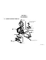
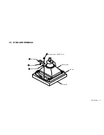
Page 9: ...CPD G220 E 1 2 1 2 US BOARD REMOVAL 1 Screw BVTP 4x8 3 Five screws BVTT 3x8 4 US board 2 ...
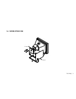
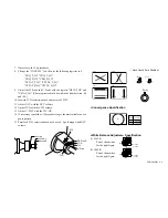
Page 11: ...CPD G220 E 1 4 1 4 SERVICE POSITION D board 2 1 3 A board ...
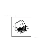
Page 26: ...CPD G220 E 4 6 4 3 CIRCUIT BOARDS LOCATION A D US H1 M DP ...
Page 39: ...CPD G220 E 4 19 H1 H1 BOARD USER CONTROL LED ...
Page 86: ...CPD G220 E 83 9 978 695 01 English 2001CL08 Data Made in Japan 2001 3 ...