background image

17

TCM-500DV

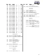
7-3. SMECHANISM  DECK  SECTION-1 (MT-500-175)

Ref. No.

Part No.

Description

Remark

Ref. No.

Part No.

Description

Remark

A (Included in No.151)

HRPE901

M601

110

111

112

103

101

102

113

104

105

114

115

105

108

109

107

107

106

106

z

101

3-704-197-01 SCREW (M1.4), SPECIAL HEAD

102

3-225-429-01 BELT (AR)

103

3-225-390-03 PULLEY (REVERSE)

104

X-3380-830-2 FLY ASSY (AR5.0), CAPSTAN

105

3-386-694-01 WASHER

106

3-029-278-01 WASHER

107

3-029-275-01 WASHER (STOPPER N)

108

3-042-480-01 SCREW (M1.4)

109

X-3379-882-3 PINCH (N) ASSY, ARM

110

3-019-776-03 GEAR (REEL-S)

111

3-225-399-04 LEVER (N SHUT OFF)

112

X-3379-883-4 PINCH (R) ASSY, ARM

113

X-3379-877-2 FLY ASSY (AR), CAPSTAN

114

3-350-949-61 SHEET (SYSTEM CONTROL SCREW)

115

3-234-856-03 LEVER (PAUSE)

HRPE901 1-500-685-21 HEAD, MAGNETIC (REC/PB/ERASE)
M601

1-763-772-12 MOTOR, DC (CAPSTAN/REEL)

(INCLUDING PULLEY)

Summary of Contents for TCM-500DV

Page 1: ...rmonic distortion Input Microphone input jack minijack sensitivity 0 2 mV for 3kΩ or lower impedance microphone Output Earphone jack minijack for 8 300Ω earphone Variable range of the tape speed From approx 30 to 15 with REC TIME PLAY MODE switch at NORMAL Power requirements 3 V DC batteries AA R6 x 2 External DC 3 V power sources Dimensions w h d incl projecting parts and controls Approx 87 6 x 1...

Page 2: ...dering or unsoldering Notes on chip component replacement Never reuse a disconnected chip component Notice that the minus side of a tantalum capacitor may be dam aged by heat SECTION 1 GENERAL REC TIME PLAY MODE VOR TAPE COUNTER z REC xSTOP REW REVIEW FF CUE VOL Flat Mic Microphone affleurant PAUSE nNPLAY n DIR N REC BATT Elamps Témoins REC BATT E MIC PLUG IN POWER EAR SPEED CONTROL SECTION 2 SERV...

Page 3: ...laws 8 Strap hand 1 Foot B 7 Cabinet rear assy 500 0 Screw B1 7 x 3 9 Flexible board CN401 Returning lever Note on Assembling Lid Assy 500 Cassette On assembling the lid assy 500 cassette insert the one side of the l id spring to the hole on the lid assy and fit the other side to the cabinet front assy 500 as shown in the figure qs Remove the lid assy 500 cassette while pushing the pivot with a ph...

Page 4: ...5 7 Mechanism deck MT 500 175 4 Jack 600 1 Belt counter 2 Screw M1 4 x 2 5 Cabinet front assy 500 3 2 MAIN BOARD 4 Cabinet front assy 500 Orange Black Red White 1 Remove four solders of capstan reel motor 3 Screws M1 4 5 MAIN board 2 Flexible board CN101 ...

Page 5: ... 3 Belt AR How to attach a belt 4 Screw M1 4 5 Capstan reel motor M601 2 Head magnetic rec pb erase HRPE901 1 Screw M1 4 3 Lid assy 500 cassette 4 Flexible board CN402 9 LED board 6 Remove two solders of mic 1 Screws 7 Sprng 500 ground 8 Mic 901 2 Screws 5 Spring earth 3 5 LED BOARD ...

Page 6: ...00DV 6 3 6 SP BOARD 6 4 Screw 9 SP board 5 Claws 2 Claw 3 Knob speed 600 Cabinet rear assy 500 1 Remove a claw of knob speed 600 by a screwdriver 7 Flexible board CN202 8 Remove four solders of speaker leads ...

Page 7: ...REC TIME switch S401 to NORMAL 4 8 cm s posi tion and playback the tape WS 48A 2 Adjust RV602 so that frequency counter reading becomes 3 010 Hz 3 Set REC TIME switch S401 to DOUBLE 2 4 cm s posi tion 4 Playback the tape from the beginning for two minutes then ad just RV601 so that frequency counter reading becomes 1 505 Hz Confirm that deflection of the frequency counter reading between the begin...

Page 8: ...SPEAKER L CH B 3V L CH 1 2 3 FWD REV R CH L CH R CH HRPE901 REC PB ERASE HEAD S401 2 2 REC TIME PLAY MODE NORMAL r DOUBLE 5 6 1 V O R LEVEL DETECT IC501 4 11 13 14 16 17 12 5 6 SERVO CONTROL IC601 D801 S402 V O R ON R OFF 15 IN THP601 S401 1 2 Q702 704 MUTE OR Q201 VDD BATT B IN A OUT A OUT A OUT B OUT B IN B SHUT DOWN VREF UOUT VOUT WOUT S S VSP OSC COM OUT M M601 CAPSTAN REEL MOTOR BATT B U V W ...

Page 9: ...e which enables seeing The other layers patterns are not indicated Caution Pattern face side Parts on the pattern face side seen Side B from the pattern face are indicated Pattern face side Parts on the parts face side seen Side A from the parts face are indicated C138 S102 POWER 11 11 1 687 887 SIDE A MAIN BOARD 2 3 4 5 6 7 8 A 1 B C D E ...

Page 10: ...12 R613 R618 R617 R609 R606 R614 R411 R607 C704 R708 R713 R712 R704 R610 R603 R705 C606 C608 C609 C607 C604 C610 C601 C405 C602 C605 C603 R608 R414 R413 R416 R415 R601 R602 R605 R615 R406 R403 R405 E B C C B E R402 R408 C403 R404 R409 R407 C404 R420 R419 R417 R418 L401 W V U COM M601 CAPSTAN REEL MOTOR SIDE B MAIN BOARD 11 11 1 687 887 REC PB r C B E B C 1 2 3 1 15 1 15 FWD t REV TO HRPE901 REC PB...

Page 11: ... 2SC4213 0 1 0 01 0 01 22 4V 22 4V 02DZ2 4 10k 10k 1 1000p 47 10 10V 0 1 0 01 10 10V 4 7 2 2k 2 2k 2 2 2 2M 1 0 47 0 47 0 22 4700p 4700p 10k 4 7k 10 10V 0 01 1 47k 47 4V 47 4V 47k 220k 4 7k 220k 10 10V MA2ZD14001S0 1 0 047 22k 10k 100k 220k 220 4V 10 10V 0 047 10k 22k 220k 0 22 100 100 1000p MA8056 10k 22 1000p 1000p 1000p 22k 220k 1 1000p 0 022 0 022 10 10V 1k 1k 22k 22k 10 10V 0 047 470k 100k 10...

Page 12: ...7 47k 10k 10 10V 100 100 10k 1M 1M 1M 1k 100 1k 10k 22k 1k 220k 10 10V 0 1 100 220 470k 1M 220k 10k 47k 1k 470 0 47 1000p 1 1k 1M 470 1k 2 2k 2 2k 1k 1k 470 47k 100k 100k 22k 4 7k 4700p 0 01 1000p 22 6 3V 1 1 470k MA111 4 7k 4 7k SML 310LTT86 SML 310LTT86 10k 47k SML 311YTT86 1000p 47k POWER UN9114J B SWITCH UN9214J B SWITCH XP4601 LED DRIVER XP1210 LED ON OFF 2SC4116 LED DRIVE 2SC4213 SPEED SWITC...

Page 13: ...IC901 1 15 A MAIN BOARD Page 10 CN201 RV201 SPEED CONTROL SPEAKER L SP901 SPEAKER R SP902 SP BOARD 11 11 1 687 888 1 15 B MAIN BOARD Page 10 t 2 3 4 5 6 A 1 B C D E Note X parts extracted from the component side a Through hole Pattern from the side which enables seeing The other layers patterns are not indicated D401 C 2 D402 C 2 D403 D 2 Ref No Location Semiconductor Location ...

Page 14: ... 2 SGND 3 POWER INA POWER INB POWER INB RFOUT RFIN 4 POWER INA 11 POWER OUTB 10 TC 12 POWER GND 15 PREOUT 16 PRE IN V 13 POWER OUTA 14 5 6 RIPPLE FILTER ALC 7 8 1 9 GND GND SHUTDOWN 2 GND 3 OUT A OUT A IN A GND IN A GND GND 4 VDD 20k 20k 20k 20k 20k 50k 50k VDD 11 BYPASS 10 IN B 12 IN B VDD VDD Z 15 GND 16 HP IN OUT B OUT B 14 19 18 17 20 20k 5 AMP 2A AMP 1A AMP 2B AMP 1B 6 13 BOOSTER CIRCUIT NC C...

Page 15: ...D 3 3 225 570 11 BUTTON FF 4 3 225 571 11 BUTTON REW 5 3 225 568 11 BUTTON PLAY L CH 6 3 225 569 11 BUTTON STOP 7 3 245 736 21 BUTTON REC 8 X 3382 992 1 CABINET FRONT ASSY 500 9 3 925 231 01 REFLECTOR 10 3 704 260 61 SCREW M1 4 11 3 248 418 11 LID BATTERY 12 3 248 440 01 SPRING LID 13 3 248 439 01 SPRING BATTERY 14 3 248 438 01 SPRING BATTERY 15 A 3663 938 A MAIN PC BOARD ASSY 16 3 345 648 01 SCRE...

Page 16: ...375 114 71 SCREW 52 3 248 449 01 CUSHION 500 MICROPHONE 53 3 250 387 01 SPRING 500 GROUND 54 3 250 382 01 SPRING 600 GROUND 55 3 248 446 01 GRILLE 500 MICROPHONE 56 3 893 942 41 SCREW 1 7X3 TAPPING B 57 X 3383 511 1 LID ASSY 500 U CASSETTE 58 1 687 886 11 FLEXIBLE BOARD 59 A 3663 937 A LED MOUNTED PC BOARD MIC901 1 476 484 31 MICROPHONE UNIT ELECTRET CAP ...

Page 17: ...03 PULLEY REVERSE 104 X 3380 830 2 FLY ASSY AR5 0 CAPSTAN 105 3 386 694 01 WASHER 106 3 029 278 01 WASHER 107 3 029 275 01 WASHER STOPPER N 108 3 042 480 01 SCREW M1 4 109 X 3379 882 3 PINCH N ASSY ARM 110 3 019 776 03 GEAR REEL S 111 3 225 399 04 LEVER N SHUT OFF 112 X 3379 883 4 PINCH R ASSY ARM 113 X 3379 877 2 FLY ASSY AR CAPSTAN 114 3 350 949 61 SHEET SYSTEM CONTROL SCREW 115 3 234 856 03 LEV...

Page 18: ...03 SLEEVE MS 155 3 728 091 01 WASHER STOPPER 156 3 225 427 01 WASHER LEVER 157 3 225 384 02 GEAR A 159 3 225 395 04 LEVER REW ROTARY 160 X 3380 677 3 LEVER E DETECTION ASSY 161 3 229 064 01 WASHER STOPPER 162 3 225 393 03 LEVER SHUT OFF 163 3 225 448 02 SPRING SHUT OFF TORSION 164 3 321 813 71 WASHER COTTER POLYETHYLENE 165 X 3379 881 3 CLUTCH ASSY AR 166 3 315 384 31 WASHER STOPPER 167 3 225 438 ...

Page 19: ... 1 104 851 11 TANTAL CHIP 10uF 20 10V C121 1 115 156 11 CERAMIC CHIP 1uF 10V C122 1 104 851 11 TANTAL CHIP 10uF 20 10V C123 1 162 970 11 CERAMIC CHIP 0 01uF 10 25V C124 1 162 970 11 CERAMIC CHIP 0 01uF 10 25V C125 1 104 851 11 TANTAL CHIP 10uF 20 10V C126 1 162 964 11 CERAMIC CHIP 0 001uF 10 50V C127 1 162 964 11 CERAMIC CHIP 0 001uF 10 50V C128 1 162 964 11 CERAMIC CHIP 0 001uF 10 50V C129 1 162 ...

Page 20: ...ETAL CHIP 10K 5 1 10W R117 1 216 825 11 METAL CHIP 2 2K 5 1 10W R118 1 216 833 11 METAL CHIP 10K 5 1 10W R119 1 216 821 11 METAL CHIP 1K 5 1 10W R121 1 216 833 11 METAL CHIP 10K 5 1 10W R122 1 216 829 11 METAL CHIP 4 7K 5 1 10W R123 1 216 825 11 METAL CHIP 2 2K 5 1 10W R125 1 216 805 11 METAL CHIP 47 5 1 10W R126 1 216 793 11 METAL CHIP 4 7 5 1 10W R127 1 216 825 11 METAL CHIP 2 2K 5 1 10W R128 1 ...

Page 21: ...0W R805 1 216 817 11 METAL CHIP 470 5 1 10W R806 1 216 813 11 METAL CHIP 220 5 1 10W R810 1 216 853 11 METAL CHIP 470K 5 1 10W R811 1 216 809 11 METAL CHIP 100 5 1 10W R813 1 216 809 11 METAL CHIP 100 5 1 10W VARIABLE RESISTOR RV101 1 225 743 11 RES VAR CARBON 10K 10K wVOL RV601 1 241 593 11 RES ADJ CERMET 4 7K TAPE SPEED 2 4cm S RV602 1 241 593 11 RES ADJ CERMET 4 7K TAPE SPEED 4 8cm S SWITCH S10...

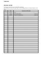
Page 22: ...vised page Also clicking the version at the upper right on the revised page allows you to jump to the next revised page Ver Date Description of Revision 1 0 2003 02 New 1 1 2003 04 JEW model addition ENG 03019 1 2 2004 04 Correction of output level SPM 04026 TCM 500DV ...

Reviews: