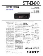
background image

SERVICE MANUAL

Sony Corporation

Published by Sony EMCS (Malaysia) PG Tec

This receiver incorporates Dolby* Digital and 
Pro Logic Surround and the DTS** Digital Sur-
round System.
*  Manufactured under license from Dolby Labo-

ratories. Dolby, Pro Logic, Surround EX, and 
the double-D symbol are trademarks of Dolby 
Laboratories.

** Manufactured under license under U.S. Pat-

ent Nos: 5,956,674; 5,974,380; 6,226,616; 
6,487,535; 7,212,872; 7,333,929; 7,392,195; 
7,272,567 & other U.S. and worldwide patents 
issued & pending. DTS-HD, the Symbol, & 
DTS-HD and the Symbol together are regis-
tered trademarks & DTS-HD Master Audio 
is a trademark of DTS, Inc. Product includes 
software. © DTS, Inc. All Rights Reserved.

This receiver incorporates High-Defi nition Multi-
media Interface (HDMI™) technology. The terms 
HDMI and HDMI High-Defi nition  Multimedia 
Interface, and the HDMI Logo are trademarks or 
registered trademarks of HDMI Licensing LLC in 
the United States and other countries.
AirPlay, iPhone, iPod, iPod classic, iPod nano, 
and iPod touch are trademarks of Apple Inc., reg-
istered in the U.S. and other countries.
All other trademarks and registered trademarks 
are of their respective holders. In this manual, ™ 
and ® marks are not specifi ed.
“Made for iPod” and “Made for iPhone” mean 
that an electronic accessory has been designed 
to connect specifi cally to iPod or iPhone, respec-
tively, and has been certifi ed by the developer to 
meet Apple performance standards.
Apple is not responsible for the operation of this 
device or its compliance with safety and regula-
tory standards. Please note that the use of this ac-
cessory with iPod or iPhone may affect wireless 
performance.
DLNA™, the DLNA Logo and DLNA CERTI-
FIED™ are trademarks, service marks, or cer-
tifi cation marks of the Digital Living Network 
Alliance.
“Sony Entertainment Network” logo and “Sony 
Entertainment Network” are trademarks of Sony 
Corporation.
Wake-on-LAN is a trademark of International 
Business Machines Corporation in the United 
States.
Windows and the Windows logo are either reg-
istered trademarks or trademarks of Microsoft 
Corporation in the United States and/or other 
countries.
This product is protected by certain intellectual 
property rights of Microsoft Corporation. Use 
or distribution of such technology outside of this 
product is prohibited without a license from Mi-
crosoft or an authorized Microsoft subsidiary.
MPEG Layer-3 audio coding technology and pat-
ents licensed from Fraunhofer IIS and Thomson.


“x.v.Color (x.v.Colour)” and “x.v.Color 
(x.v.Colour)” logo are trademarks of Sony Cor-
poration.
“BRAVIA” is a trademark of Sony Corporation.
“PlayStation” is a registered trademark of Sony 
Computer Entertainment Inc.

STR-DN840

MULTI CHANNEL AV RECEIVER

9-890-617-01

2013B80-1

© 

2013.02

Ver. 1.0  2013.02

US Model

Canadian Model

AEP Model

UK Model

Australian Model

SPECIFICATIONS

“WALKMAN” is a registered trademark of Sony 
Corporation.
MICROVAULT is a trademark of Sony Corpora-
tion.
VAIO and VAIO Media are registered trademarks 
of Sony Corporation.
PARTY STREAMING and PARTY STREAM-
ING logo are trademarks of Sony Corporation.
The Wi-Fi CERTIFIED Logo is a certifi cation 
mark of the Wi-Fi Alliance.
The 

Bluetooth

®

 word mark and logos are regis-

tered trademarks owned by Bluetooth SIG, Inc. 
and any use of such marks by Sony Corporation 
is under license.
Other trademarks and trade names are those of 
their respective owners.
InstaPrevue™ is a trademark or registered trade-
mark of Silicon Image, Inc. in the United States 
and other countries.

FLAC Decoder

Copyright (C)
2000,2001,2002,2003,2004,2005,2006,2007 
Josh Coalson
Redistribution and use in source and binary 
forms, with or without modifi cation, are permit-
ted provided that the following conditions are 
met:
–  Redistributions of source code must retain the 

above copyright notice, this list of conditions 
and the following disclaimer.

–  Redistributions in binary form must reproduce 

the above copyright notice, this list of condi-
tions and the following disclaimer in the docu-
mentation and/or other materials provided with 
the distribution.

–  Neither the name of the Xiph.org Foundation 

nor the names of its contributors may be used 
to endorse or promote products derived from 
this software without specifi c prior written per-
mission.

THIS SOFTWARE IS PROVIDED BY THE 
COPYRIGHT HOLDERS AND CONTRIBU-
TORS “AS IS” AND ANY EXPRESS OR IM-
PLIED WARRANTIES, INCLUDING, BUT 
NOT LIMITED TO, THE IMPLIED WARRAN-
TIES OF MERCHANTABILITY AND FIT-
NESS FOR A PARTICULAR PURPOSE ARE 
DISCLAIMED. IN NO EVENT SHALL THE 
FOUNDATION OR CONTRIBUTORS BE LI-
ABLE FOR ANY DIRECT, INDIRECT, INCI-
DENTAL, SPECIAL, EXEMPLARY, OR CON-
SEQUENTIAL DAMAGES (INCLUDING, 
BUT NOT LIMITED TO, PROCUREMENT OF 
SUBSTITUTE GOODS OR SERVICES; LOSS 
OF USE, DATA, OR PROFITS; OR BUSINESS 
INTERRUPTION) HOWEVER CAUSED AND 
ON ANY THEORY OF LIABILITY, WHETH-
ER IN CONTRACT, STRICT LIABILITY, 
OR TORT (INCLUDING NEGLIGENCE OR 
OTHERWISE) ARISING IN ANY WAY OUT 
OF THE USE OF THIS SOFTWARE, EVEN IF 
ADVISED OF THE POSSIBILITY OF SUCH 
DAMAGE.

AUDIO POWER
SPECIFICATIONS

POWER OUTPUT AND TOTAL
HARMONIC DISTORTION:
(US model only)

With 6 ohm loads, both channels driven, from 
20 – 20,000 Hz; rated 100 watts per channel 
minimum RMS power, with no more than 0.09% 
total harmonic distortion from 250 milliwatts to 
rated output.

Amplifi er section

Minimum RMS Output Power

1)

(6 ohms, 20 Hz – 20 kHz, THD 0.09%)
 

95 W + 95 W

Stereo Mode Output Power

1)

(6 ohms, 1 kHz, THD 1%)
 

110 W + 110 W

Surround Mode Output Power

1) 2)

(6 ohms, 1 kHz, THD 0.9%)


150 W per channel

1)

 Measured under the following conditions:

Area

Power requirements

US, Canadian

120 V AC, 60 Hz

AEP, UK, 
Australian

230 V AC, 50 Hz

2)

 Reference power output for front, center, sur-

round, surround back and front high speakers. 
Depending on the sound fi eld settings and the 
source, there may be no sound output.

Frequency response
  Analog 

10 Hz – 100 kHz, 
+0.5/–2 dB (with sound 
fi eld and equalizer 
bypassed)

Input
  Analog 

Sensitivity: 500 mV/
50 kilohms


S/N

3)

: 105 dB

(A, 500 mV

4)

)


Digital (Coaxial) 

Impedance: 75 ohms 
S/N: 100 dB
(A, 20 kHz LPF)


Digital (Optical) 

S/N: 100 dB


(A, 20 kHz LPF)

Output (Analog)
  SUBWOOFER 

Voltage: 2 V/1 kilohm

Equalizer
  Gain levels 

±10 dB, 1 dB step

3) 

INPUT SHORT (with sound fi eld and equalizer 
bypassed).

4) 

Weighted network, input level.

FM tuner section

Tuning range 

87.5 MHz – 108.0 MHz
(50 kHz step) 
(AEP, UK, Australian)
87.5 MHz – 108.0 MHz
(100 kHz step) 
(US, Canadian)

Antenna (aerial) 

FM wire antenna (aerial)

Antenna (aerial) terminals
   

75 ohms, unbalanced

AM tuner section

Tuning range

Area

Tuning scale

10 kHz step 

9 kHz step

US, Canadian

530 kHz – 

531 kHz –

1,710 kHz 

1,710 kHz

AEP, UK, 
Australian

        – 

531 kHz –

 1,602 

kHz

Antenna (aerial) 

Loop antenna (aerial)

Video section

Inputs/Outputs

  Video: 

1 Vp-p, 75 ohms

– Continued on next page –

Summary of Contents for STR-DN840

Page 1: ...y use of such marks by Sony Corporation is under license Other trademarks and trade names are those of their respective owners InstaPrevue is a trademark or registered trade mark of Silicon Image Inc in the United States and other countries FLAC Decoder Copyright C 2000 2001 2002 2003 2004 2005 2006 2007 Josh Coalson Redistribution and use in source and binary forms with or without modification ar...

Page 2: ...tion sensitivity antenna s performance operating system software application etc 2 Bluetooth standard profiles indicate the purpose of Bluetooth communication between devices 3 Codec Audio signal compression and conversion format 4 Subband Codec General Power requirements Area Power requirements US Canadian 120 V AC 60 Hz AEP UK Australian 230 V AC 50 60 Hz Power consumption 240 W Power consumptio...

Page 3: ... this job 3 Measuring the voltage drop across a resistor by means of a VOM or battery operated AC voltmeter The limit indication is 0 75 V so analog meters must have an accurate low voltage scale The Simpson 250 and Sanwa SH 63Trd are examples of a passive VOM that is suitable Nearly all battery operated digital multimeters that have a 2 V AC range are suitable See Fig A 1 5 kŸ 0 15 F AC voltmeter...

Page 4: ...33 5 15 Schematic Diagram DIGITAL Board 7 8 34 5 16 Schematic Diagram DIGITAL Board 8 8 35 5 17 Printed Wiring Board MAIN Board Component side 36 5 18 Printed Wiring Board MAIN Board Conductor side 37 5 19 Schematic Diagram MAIN Board 1 4 38 5 20 Schematic Diagram MAIN Board 2 4 39 5 21 Schematic Diagram MAIN Board 3 4 40 5 22 Schematic Diagram MAIN Board 4 4 41 5 23 Printed Wiring Board DISPLAY B...

Page 5: ... can be used but the iron tip has to be applied to the solder joint for a slightly longer time Soldering irons using a temperature regulator should be set to about 350 C Caution The printed pattern copper foil may peel away if the heated tip is applied for too long so be careful Strong viscosity Unleaded solder is more viscous sticky less prone to flow than ordinary solder so use caution not to le...

Page 6: ...ng the memory r a e l c o T All memorized settings Customized sound fields Reverting back to the factory default settings You can clear all memorized settings and revert the receiver back to the factory default settings by performing the following procedure This procedure can also be used to initialize the receiver before you use it for the first time Be sure to use the buttons on the receiver to ...

Page 7: ...own below 2 1 DISASSEMBLY FLOW 2 2 CASE ENTRY Page 8 2 6 DCDC BOARD STANDBY BOARD GND BRACKET BOARD Page 11 2 7 BACK PANEL SECTION MAIN BOARD SECTION Page 12 2 8 MAIN BOARD Page 13 2 5 DIGITAL BOARD NETWORK MODULE Page 10 2 4 FRONT PANEL SECTION Page 9 2 3 TUNER1 ASSY Page 8 SET ...

Page 8: ...rocedure in the numerical order given 2 2 CASE ENTRY 2 3 TUNER1 ASSY 3 three screws BVTP 3 u 8 4 2 three screws B TYPE 4 u 8 5 case entry 1 three screws B TYPE 4 u 8 4 1 wire flat type 9 core CN101 2 two screws BVTP 3 u 8 3 TUNER1AMF ASSY US CND TUNER1AMPR ASSY except US CND ...

Page 9: ...one screw BVTP 3 u 8 0 one screw BVTP 3 u 8 1 Wire is removed from the pin lead 3 Wire is removed from the pin lead INSULATION board heat sink pin lead LUH VHWWLQJ front side LUH VHWWLQJ USB WIRE INSULATION PC board heat sink pin lead front side 5 wire flat type 14 core CN4800 6 cushion R 86 1 86 1 2 CN4000 5P qa front panel section 86 1 ...

Page 10: ...screws B 3 u 5 qs one screw BVTP 3 u 8 qd four screws BVTP 3 u 8 qg one screw BVTP 3 u 8 qf two screws BVTP 3 u 8 qf two screws BVTP 3 u 8 qf one screw BVTP 3 u 8 qg three screws BVTP 3 u 8 qh bracket HDMI N84 ql DIGITAL board 4 NETWORK module 3 CN7002 120P 8 wire flat type 25 core CN2002 0 wire flat type 25 core CN2000 qk copper shield qj bracket beam N84 US CND except US CND except US CND US CND...

Page 11: ...lamp sleeve ferrite except US CND except US CND US CND qa two screws BVTP 3 u 8 qd DCDC board 8 cushion R qf Cut the cable tie clamp sleeve ferrite LUH VHWWLQJ rear side rear side DCDC board US CND US CND DCDC board cushion R cushion R clamp sleeve ferrite DIGITAL board cable tie except US CND except US CND Note Process so that lead wire does not contact with power transformer Note Process so that...

Page 12: ...a USB WIRE INSULATION PC board 9 INSULATION board qd two screws BVTP 3 u 8 4 back panel section qg MAIN BOARD section 2 five screws BVTP 3 u 8 5 Wire is removed from the pin lead 7 CNP930 5P 6 CNP920 5P LUH VHWWLQJ pin lead chassis MAIN board rear side 3 8 86 3 four screws BV ring except US CND four screws BVTP 3 u 8 US CND Abbreviation AUS Australian model CND Canadian model ...

Page 13: ...STR DN840 13 2 8 MAIN BOARD Note This illustration sees the MAIN board from back side 3 heat sink section 2 two screws BVTP 3 u 8 4 MAIN board 1 Remove the forty two solders ...

Page 14: ... the main power 2 The message N84 XXX appears XXX Area display Each time the DISPLAY button is pressed SYS vX XXX MAIN vX XX VIDEO vX XX OSD vX XX SFLASHvX XX and NET vX XX appear in this order and returns to the N84 XXX display X XX Software version KEY CHECK MODE Each button can be checked Procedure 1 While pressing SPEAKERS and PURE DIRECT buttons simultaneously press the 1 button to turn on th...

Page 15: ... x Center Level C x x x x x x Surround Level S x x x x x x Surround Back Level B x x x x x x Front Height Level H x x x x x x Temperature T E M P Total Power On T x x x x x H x x M Main Power On M x x x x x H x x M Power On Count R E B O X x x USB UPDATE TEST MODE To update micontroller software through USB Procedure 1 Plug in USB device in power off condition 2 While pressing TUNING MODE and PURE...

Page 16: ...etting and press the key of remote commander 11 Either one of the display below appears according to the destination of the set Items Display Destination D E S T U N F I X Destination UCA fix U C A f i x Destination J fix J f i x Destination TW fix T W f i x Destination SP CN fix C N f i x Destination KR fix K R f i x Destination E2 E3 fix C H 3 f i x Destination CEL fix C E L f i x Destination AU...

Page 17: ...Hz Modulation 1 kHz ANT input 35 dBu EMF Note Use 75 ohm coaxial cable to connect signal generator and the set You cannot use video cable for checking Use signal generator whose output impedance is 75 ohm 3 Set to FM tuner function and scan the input FM signal with automatic scanning 4 Confirm that input frequency of A B and C are detected and automatic scanning stops When the station signal is re...

Page 18: ...RAMS Circuit Boards Location Abbreviation CND Canadian model DCDC board MAIN board NETWORK module DIGITAL board TUNER1 board DISPLAY board STANDBY board POWER KEY board HEADPHONE board FRONT JACK PWB board BLUETOOTH module US CND ...

Page 19: ...NR1 1 OUT1 LINEAMP IC410 63 6 2 1 64 7 R ch R ch R ch FLOUT INL6 BTLOut INR6 BTROut LINEAMP IC420 53 2 3 5 6 1 54 7 R ch R ch BT_R BT_L SYSTEM CONTROL IC2100 1 6 11 TUNER_MOSI 10 TUNER_CLK EVOL_DATA DATA CLK EVOL_CLK 3 2 ZONE2_PREOUT_SW_RY 89 57 58 10 11 59 60 75 14 13 20 19 15 C 18 R ch R ch R ch R ch 17 43 44 51 52 47 48 16 76 AUDIOAMP IC100 R ch R ch R ch R ch R ch R ch R ch INL10 INR10 45 46 R...

Page 20: ...8 15 DAC_IIC_SDL DAC_IIC_SCA INITX SCK 3 MC SCL DEMP MD SDA MUTE DATA4 DATA3 FLOUT R CH VOUT1 VOUT2 VOUT5 VOUT6 VOUT3 VOUT4 13 26 27 6 7 BCK LRCK 8 MPOUT1 MPOUT4 DATAOUT 19 SL SR_IN A D_2CH DIR_IN L R_IN 74 MPOUT2 20 16 22 103 100 96 C SW_IN 95 MPOUT3 21 SBL SBR_IN 101 D ACONVERTER IC2104 DATA2 SLOUT R CH 19 20 DATA1 COUT 22 SWOUT 21 ADINL ADINR 12 VOUT7 VOUT8 15 16 SBLOUT 11 EEPROM IC2102 BINARY ...

Page 21: ...R Q852 Q853 CURRENT DETECT Q854 CURRENT DETECT Q855 SL LIMITER Q702 Q703 BOOSTER Q700 CURRENT DETECT Q704 CURRENT DETECT Q705 BOOSTER Q701 LIMITER Q752 Q753 BOOSTER Q750 CURRENT DETECT Q754 CURRENT DETECT Q755 BOOSTER Q751 SYSTEMCONTROL IC2100 3 6 C PROTECT TEMP_SENSOR_2 TEMP_SENSOR_1 LIMITER HP_RY FRONT_SPK_RY SBL_SBR_RY C SL_SR_RY HP_DET LIMITER Q552 Q553 BOOSTER Q550 CURRENT DETECT Q554 CURRENT...

Page 22: ... 6 V_MUTE V_SEL_SW2 SYSTEMCONTROL IC2100 4 6 MUTE PROTECTION Q281 Q283 5 74 4 3 EN FAULT Prog_VUTX NETWORKSELECTOR IC3002 125 2 1A Prog_VURX 126 7 2Y 10 3B 12 4Y EN 4 BT_R BT_L ANALOGAUDIO SECTION Page19 D 3 3V BTRX BTTX CN4800 12 5 9 8 LCH_N RCH_P LCH_P 3 4 RCH_N 2 BTMODULE CN7002 CN7000 74 33 76 58 56 38 36 106 108 112 114 6 RX RX TX TX 5 4 3 NETWORK MODULE J218 1 2 J218 2 2 CN106 D D DC5V 1AMAX...

Page 23: ... 165 MU_RST 97 HDMICONTROLLER IC3000 2 2 VCOM_RESET 42 INITX 38 SYSTEMCONTROL IC2100 5 6 CS 1 SCK 6 DO 2 DI 5 SELECTOR IC3502 95 4 RESET IC3001 1 4 5VREG IC3204 D3002 D3005 D3006 D3003 159 T0X2 DATA2 DATA2 DATA1 DATA1 DATA0 DATA0 CLOCK CLOCK SCL 5V SDA 5V HOTPLUGDET CEC 5VPOWER T0X2 T0X1 T0X1 T0X0 T0X0 T0XC T0XC TXDSCL0 158 157 156 155 154 153 152 107 TXDSDA0 TX_HPD0 5V 106 105 124 126 128 121 122...

Page 24: ... IC350 7VREG IC351 7VREG IC352 5VREG IC2106 5VREG IC2110 3 3VREG IC102 RELAY DRIVE Q920 3 6VREG IC1902 1 2VREG IC7000 DCDC_NWREG IC1901 1 2V 3 3VREG STBY IC901 1 2VREG IC2500 1 2VREG IC3508 5V F1 F2 5VREG IC3503 5V USB VBUS 5VREG USB VBUS IC4103 5V USB VBUS 5VREG USB VBUS IC4102 2VREG IC1903 6VREG IC1904 RELAY DRIVER Q901 DCCONVERTER TRANSFORMER T100 SWITCHING TRANSISTOR Q102 LEDDRIVER Q105 LED PU...

Page 25: ...fié Caution Pattern face side Conductor Side Parts face side Component Side Parts on the pattern face side seen from the pattern face are indicated Parts on the parts face side seen from the parts face are indicated HDMI board and DSP board are multi layer printed board However the patterns of intermediate layers have not been included in diagrams Indication of transistor C B These are omitted E Q...

Page 26: ...039 RB2101 RB2102 C3550 RB2106 RB2107 CL7040 RB2108 CL7041 RB2109 CL7042 C3363 CL7043 C3364 CL7044 RB2110 CL7049 2 1 7 6 CN7001 CN7002 1 2 120 119 CL7050 RB2500 FB4000 RB2501 CL2232 RB2502 CL7052 C3373 RB2503 C3374 C7006 C7007 C7008 1 2 25 24 CN2000 C7009 1 2 25 24 CN2002 1 13 CN2003 1 2 CN2004 C7010 C7011 C7012 C7013 C7014 C7015 C7016 C7017 J2100 X2100 C7021 C7022 X2102 C7023 R3370 R3371 C2205 R3...

Page 27: ...CL2012 R3512 R2573 CL2013 R3513 CL2014 R3514 R2575 CL2015 R3515 CL2016 R3516 R2577 CL2017 R3517 R2578 C3540 CL2018 R3518 R2191 R2579 C3541 CL2019 R3519 R2192 C3542 C3543 C1604 R2194 C3544 C1605 C3545 C1606 C3546 C1607 C3548 CL2020 R3520 CL2021 R3521 R2582 CL2022 R3522 CL2023 R3523 CL2024 R3524 R2585 C3359 CL2025 R3525 R2586 CL2026 R3526 CL2027 RB2103 CL2028 C3551 CL2029 R3529 C3552 C3553 C3554 C16...

Page 28: ...V 1 MCLK 2 BICK 3 SDTI 4 LRCK 5 RSTN 6 SMUTE 7 ACKS 8 DIF0 9 DIF1 10 R OUT 11 L OUT 12 VCOM 13 VSS 14 VDD 15 DEM 16 DZF IC2000 TC74VHC08FT EL 1 2 3 4 5 6 7 8 9 10 11 12 13 14 C2033 220p 2 1 A 5V 7V 7V AGND DGND 3 3V FB2003 0uH TUNER_GND CL2009 CL2010 CL2011 CL2012 CL2013 CL2014 CL2015 CL2016 CL2017 CL2018 CL2019 CL2020 CL2021 CL2023 CL2025 CL2027 CL2028 CL2032 CL2034 CL2035 CL2036 CL2037 CL2038 CL...

Page 29: ...2108 10010V 4 0 R2284 C2171 4 7 IC2110 MM3411A50NRE C2151 470 10V C2133 220 6 3V C2199 0 1 C2204 0 1 C2183 100p C2182 100p 4 7 C2179 0 1 C2170 0 1 C2129 0 1 C2166 0 1 C2168 0 1 C2106 0 1 C2127 0 1 R2177 1k R2178 1k C2150 0 1 C2154 0 01 C2157 0 001 C2181 0 1 C2132 C2135 0 1 C2126 0 1 C2173 0 1 C2178 0 01 C2174 470 10V C2172 0 1 C2152 0 1 C2155 0 01 C2156 0 001 C2153 470 10V 0 1 C2128 C2167 0 1 C216...

Page 30: ...C2192 C2194 C2187 0 1 C2188 0 001 C2196 0 001 C2195 0 001 16 VCC 15 ST 14 4A 13 4B 12 4Y 11 3A 10 3B 7 2Y 9 3Y 8 GND 6 2B 5 2A 4 1Y 3 1B 2 1A 1 SEL IC2113 TC74VHC157FT EKJ 16 VCC 15 ST 14 4A 13 4B 12 4Y 11 3A 10 3B 7 2Y 9 3Y 8 GND 6 2B 5 2A 4 1Y 3 1B 2 1A 1 SEL 10 C2189 0 1 MUTE SELECTOR IC2108 0 1 C2193 10 ICB D SIGNAL SELECTOR IC2113 ICB D IC2114 TC74VHC157FT EKJ SIGNAL SELECTOR IC2114 ICB D 0 1...

Page 31: ...2PD601ART 1k R2290 Q2105 PDTC114ET 10k R2296 220 R2295 NW_WAKE 100 R2297 100 R2168 10k R2298 0 1 C2208 CL2140 1k R2110 C2138 C2136 C2206 0 1 C2111 0 1 C2137 0 1 C2186 0 001 C2191 0 1 C2140 0 1 C2147 C2205 0 1 C2143 0 1 C2117 0 1 C2210 1000p C2149 0 1 C2109 0 1 C2207 0 1 C2197 0 001 C2198 0 001 1 2 3 4 5 6 7 1 2 3 4 5 6 7 STDBY_LED POWON_LED FL_BK DCDC_MUTE FL_DATA FL_LAT FL_CLK INPUT_JOG AD_KEY1 A...

Page 32: ...M 2 MS0 3 SDCKE 4 VDD_INT 5 CLK_CFG1 6 ADDR0 7 BOOT_CFG0 8 VDD_EXT 9 ADDR1 10 ADDR2 11 ADDR3 12 ADDR4 13 ADDR5 14 BOOT_CFG1 15 GND 16 ADDR6 17 ADDR7 18 NC 19 NC 20 ADDR8 21 ADDR9 22 CLK_CFG0 23 VDD_INT 24 CLKIN 25 XTAL2 26 ADDR10 27 SDA10 28 VDD_EXT 29 VDD_INT 30 ADDR11 31 ADDR12 32 ADDR17 33 ADDR13 34 VDD_INT 35 ADDR18 36 RESETOUT RUNRSTIN 37 VDD_INT 38 MOSI 39 MISO 40 SPICLK 41 VDD_INT 42 DPI_P0...

Page 33: ...6 D3003 CES521 FB3000 0uH 100 R3002 DGND DGND Q3000 RESET SW LTC014EUBFS8TL JL3015 JL3016 JL3009 JL3011 JL3012 JL3013 JL3014 3 DCDC_NW JL3020 JL3021 JL3022 JL3023 JL3024 Q3004 SW RESET LTC014EUBFS8TL 10k R3063 JL3025 JL3026 JL3027 JL3028 JL3029 JL3030 JL3031 JL3032 JL3033 JL3034 17 COMP_DET 1 2 3 4 5 6 7 VU_MD0 Prog_VUSCK JIG_RESET CN3000 7P MD0 RESET Prog_VUTX SCK Prog_VURX GND 3 3V JL3003 JL3004...

Page 34: ... 7k R3581 4 7k R3582 CN3201 19P 1 DATA2 2 DATA2 SHIELD 3 DATA2 4 DATA1 5 DATA1 SHIELD 6 DATA1 7 DATA0 8 DATA0 SHIELD 9 DATA0 10 CLOCK 11 CLOCK SHIELD 12 CLOCK 20 21 13 CEC 14 RESERVE NC 15 SCL 5V 16 SDA 5V 17 DDC CEC GND 18 5V POWER 19 HOT PLUG DET 22 23 RB3204 0 RB3205 0 C3363 1 C3364 1 1 8k R3386 47k R3376 47k R3377 1k R3380 300 R3370 300 R3371 62 R3372 62 R3374 C3358 1 0 R3373 1 8k R3387 ET3001...

Page 35: ... 35 36 37 38 39 40 41 42 43 44 45 46 47 48 49 50 51 52 53 54 55 56 57 58 59 60 NPD_RF A22 DA810 0 R7006 CL7028 CL7020 47 R7026 CL7040 CL7053 CL7054 CL7018 CL7039 47 R7024 10k R7014 0 R7012 0 R7011 10k R7013 10k R7016 10k R7015 10k R7018 10k R7017 CL7034 CL7030 CL7042 CL7026 0 R7007 CL7023 CL7021 C7017 68p C7015 15p C7013 0 1 C7011 1 C7016 68p C7014 15p C7012 0 1 C7010 1 CL7019 47 R7033 47 R7034 0 ...

Page 36: ...51 C322 R553 C323 R554 R361 R555 C325 R556 R558 C710 R365 C712 C713 R750 R751 R753 R754 R561 R755 R756 R758 R566 C912 R567 C913 C720 R377 R761 R570 R571 RY301 R572 R766 R573 R767 R574 R575 R576 R577 R578 R579 C731 C732 R770 R771 C735 R772 R773 R774 C350 R775 C351 C545 R776 C352 C546 R777 C353 C547 R778 C354 R779 C355 C931 GP801 C932 C933 C358 C359 C553 C558 C753 C560 C563 C758 Q600 1 4 CN391 Q601 ...

Page 37: ... C892 CL397 CL398 CL399 Q554 E Q555 E R301 D650 R304 D651 R307 R308 R309 Q754 E E Q755 D850 D851 R702 R707 R320 R709 R323 R714 R715 R718 R719 R532 R533 R534 R921 R925 R732 R733 R734 C505 C506 R350 R544 R353 R355 C701 R358 C704 C705 C706 CL400 CL401 R552 CL402 CL403 R360 CL404 CL405 CL406 R363 R557 CL407 CL408 CL215 R559 CL409 CL216 R366 R367 CL217 CL218 CL219 R752 CL410 CL411 CL412 R757 CL413 R564...

Page 38: ...p C781 4p Q772 KTA1024 Y Q775 KTC3206 Y Q774 KTC3206 Y D822 DA2J10100L 2 2k R825 D820 DA2J10100L 2 2k R827 56k R829 4 7k R820 4 7k R821 4 7k R822 D821 DA2J10100L 270 R828 470 R826 220 R823 220 R824 Q820 PWRAMP PWRAMP PWRAMP C820 3300p C835 47p C831 4p Q822 KTA1024 Y Q825 KTC3206 Y Q824 KTC3206 Y D622 DA2J10100L 2 2k R625 D620 DA2J10100L 2 2k R627 56k R629 4 7k R620 4 7k R621 4 7k R622 D621 DA2J101...

Page 39: ...BA60 F Q320 2SA1514KT146S Q323 2SA1514KT146S C914 0 22 C915 0 22 D360 DA2J10100L 22k R323 22k R320 C320 220 10V C323 220 10V D920 DA2J10100L R361 33 R920 33 CC66 220p CC65 220p CC60 220p CC61 220p CC64 220p CC62 220p CC63 220p CL366 CL367 CL368 F910 2 5A250V F911 2 5A250V CNP930 5P R2AC 2 1 3 4 5 CENTERTAP NC R2AC RR17 10 CC17 0 01 330 R395 D375 DA2J10100L 2 2k R375 330 R392 C322 0 01 47k R378 CL3...

Page 40: ...41 CL218 CL219 1 2 3 4 5 6 7 8 9 10 11 12 13 14 15 16 17 18 19 20 21 22 23 24 25 VCC OUT GND VCC OUT GND JL2871 JL2870 C2370 IC2351 JSR1124 JL2869 C2351 0 1 C2354 0 1 IC2352 JSR1124 0uH FB2890 JL2868 100 R2351 100 R2354 10 7 MAINBOARD 4 4 Page41 8 MAIN BOARD 4 4 Page41 HP C_SUR PROTECT HP_DET DATA CLK DCAC_IN TUNER_L TUNER_R TUNER_GND NW_R_VOLIC_OUT NW_L_VOLIC_OUT SW SBL_R BRIDGE LR 220 R450 220 R...

Page 41: ...INR5 57 INL4 58 INR4 59 INL3 60 INR3 INL2 INR2 INL1 INR1 GND SBLIN SBRIN SLIN SRIN CIN SWIN FLIN FRIN GND ADCROUT ADCLOUT GND SUB1R SUB1L GND OUT1 1 1 VSS 2 2 OUT2 VCC C421 1000p C427 1000p C428 1000p C423 1000p C424 1000p C425 1000p C426 1000p C422 1000p C706 270p C756 270p R783 R784 820 15k R734 15k R733 820 C310 47010V C311 47010V C506 270p R533 R534 820 15k C656 270p R683 R684 820 1 5k C856 27...

Page 42: ...0 R104 C110 R129 R114 C116 R153 R127 R115 CL134 R135 R105 C104 CL125 R154 R146 R128 R116 R100 C100 R133 R111 C117 C107 JR JR116 JR JR117 JR JR100 JR111 JR JR121 JR JR131 JR JR129 JR JR104 JR JR133 JR JR137 JR JR127 JR JR124 JR JR130 JR JR102 JR JR135 JR JR139 JR JR119 JR JR123 JR JR136 JR JR JR JR125 JR JR118 JR JR JR115 JR JR103 JR JR101 JR106 JR JR JR110 JR132 JR107 JR JR113 JR JR144 JR JR145 JR...

Page 43: ...RANSISTOR CONTROL VACUUM FLOURESCENT DISPLAY ND100 2 53 54 49 50 47 48 45 46 43 44 42 40 41 38 39 1 1 2 3 4 5 6 7 8 9 10 11 12 13 14 15 16 17 18 19 20 21 22 23 24 25 AD1 POWER_BUTTON DCAC_SIGNAL FL_EN FL_EN LED_ON LED_STBY CL115 CL116 CL117 CL118 CL119 CL120 CL121 CL122 CL123 CL124 CL126 CL129 CL130 CL136 CL138 CL131 CL132 CL133 CL134 CL135 CL137 CN102 25P LED_STBY LED_ON FL_BK 3 3V_DCDC 7V 7807 A...

Page 44: ...2 L1903 L1904 L1907 L1908 L1909 D923 F941 1 4 CN941 C1905 C1907 C1906 C1961 C1966 C1910 C1965 C1912 C1960 C1967 C1911 C1962 F940 1 2 CN901 1 11 CN1901 C1947 C1945 C1946 R1965 R1939 R1938 R1937 R1925 R1913 LP1901 R1905 L1901 C1969 C1964 C1944 C1934 C1929 C1924 C1914 C1909 C900 L1906 R1964 CL948 CL946 CL942 CL941 CL943 C1971 C1951 C1957 C1972 C1955 C1949 C1952 C1956 C1973 C902 C907 C908 CL911 CL909 ...

Page 45: ...L1901 10uH L1903 10uH L1902 10uH L1904 10uH 0 R1942 22 R1925 C1936 0 1 22 R1927 C1935 0 1 22 R1926 C1937 0 1 22 R1928 25V C1904 100 25V C1969 10 C1964 10 C1909 0 1 C1906 100 C1967 10 C1962 10 C1911 0 1 25V C1905 100 C1966 10 C1961 10 C1910 0 1 25V C1907 100 C1965 10 C1960 10 C1912 0 1 C1946 100 10V C1949 22 C1972 22 0 1 C1955 C1945 100 10V CN1901 11P NC 1 6V 6V DCDC_NW DCDC_NW 3 6V 3 6V 2V 2V 2 5V...

Page 46: ...1 7 CN952 CL951 CL956 CL957 CL955 CL952 CL953 CL901 CL900 CL904 CL908 CL905 C983 CL954 R951 D904 D905 D900 C986 D901 C985 D903 R904 R903 Q901 E POWER TRANSFORMER SUB STANDBYBOARD COMPONENTSIDE STANDBYBOARD CONDUCTORSIDE 1 887 629 21 21 1 887 629 21 21 H DIGITAL BOARD CN1500 Page27 O DCDC BOARD CN901 Page44 T901 POWER TRANSFORMER MAIN I MAINBOARD CNP920 Page36 N DCDCBOARD CN941 Page44 J MAINBOARD C...

Page 47: ...4 47k R904 CL952 CL951 FH901 CL954 C983 0 1 0 R951 CL900 CL901 CL904 CN940 7P POWER_Relay AC_CUT Stby3 3V Stby3 3V 7 StbyGND StbyGND IC901 RT7237ALGSP 1 BOOT 2 VIN 3 SW 4 GND 5 FB 6 COMP 7 EN 8 9 SS GND CL905 C987 0 1 L001 10uH 75k R952 24k R953 C980 22 C989 3300p C992 0 1 R954 15k C988 22 C991 10 C981 10 R913 4 7 R914 22 D902 BAV70 1 POWER TRANSFORMER SUB T902 RY951 5V TV 8 Q900 2PD601ART ACOFFDE...

Page 48: ... 3 4 5 6 7 8 IC101 IC102 1 2 4 3 X101 L101 FL101 I G O 2 1 8 9 CN101 1 3 CN103 A001 CN102 CN104 R106 R105 R103 R101 R110 C105 C101 C111 C112 D103 C109 C103 R107 C108 C102 C107 L105 D102 D101 C106 JR JR101 R104 JR JR102 JR JR105 R108 R109 JL113 JR JR109 JR JR112 C110 R113 JR JR106 L103 L104 JL107 JL117 JL112 JL118 JL102 JL108 JL115 JL106 JL109 JL104 JL103 JL105 JL116 JL110 JL111 JL114 JL131 JL125 J...

Page 49: ...13 ROUT 14 LOUT 15 IISD 16 CP1 17 X1 18 X2 19 VDD 20 JL112 JL102 JL104 JL106 JL108 JL110 JL103 JL105 JL107 JL109 JL115 JL114 JL111 JL113 0 R104 1 2 3 4 5 6 7 8 9 9P CN101 IISD dataaudio VDD AUDIOL LRCK CE pcon AUDIOR BCK GND DA forIIC IIC RDSI CK forIIC JL118 JL117 JL116 1 2 3 3P CN103 AM AM FM 10k R113 CN102 3P 3P 1 CE 2 3 Vout 4 Vdd MM3404A33URE IC102 GND 0 047 C107 C110 10 470p C101 1 C102 1 C1...

Page 50: ...79 Q110 LEDDRIVER LEDDRIVER 2PD601ART D110 SML78423C TP15 2 2k R174 S114 SPEAKERS LED ON STBY S112 TUNING S111 TUNING S115 1 S113 TUNING MODE L DISPLAY BOARD CN100 Page43 1 A B 2 3 4 5 HEADPHONEBOARD 1 3 4 5 CL185 CL186 CL187 CL188 CN107 5P HP_DETECT HP_R HP_GND HP_L C160 1000p C162 1000p C161 1000p J101 PHONES I MAIN BOARD 2 4 CN391 Page39 1 A B C D E F G 2 3 4 5 6 7 8 1 8 3 CN103 S111 S112 S113 ...

Page 51: ... 14 13 12 11 10 9 8 IC2001 AK4388AET2 E2 DIGITAL BOARD 1 8 1 CLOCK DIVIDER DE EMPHASIS CONTROL AUDIO DATA INTERFACE MCLK 2 11 BICK 3 SDTI 4 LRCK 5 RSTN CONTROL PORT 6 SMUTE 7 ACKS 8 DIF0 8 INTERPOLATOR 8 INTERPOLATOR MODULATOR MODULATOR SCF LPF SCF LPF AOUTL 12 VCOM 13 VSS 14 VDD 15 DEM 16 DZF 10 AOUTR 9 DIF1 VDD 1 GND 2 CE 3 VREF OCP TSD STBY Discharge 5 VOUT 4 NC ...

Page 52: ...15 13 14 12 11 9 10 IC2101 BU4229F TR DIGITAL BOARD 4 8 IC3001 BU4229F TR DIGITAL BOARD 6 8 VDD 2 OUT 1 VSS 3 VREF CD 5 NC 4 DELAY CIRCUIT IC2102 BR24T64FJ WE2 DIGITAL BOARD 4 8 1 A0 A1 2 A2 3 GND 4 1Kbit 1024Kbit EEPROM array Address decoder 7bit 8bit 9bit 10bit 11bit 12bit 13bit 14bit 15bit 16bit 17bit 1 1 Controlcircuit START STOP ACK Highvoltage generatingcircuit Powersource voltagedetection W...

Page 53: ...ODULATOR SYSTEMCLOCK MANAGER ZERO DETECT POWER SUPPLY SYSTEM CLOCK ZR2 28 VOUT1 27 D A CONVERTER OUTPUTAMPAND LOW PASSFILTER OUTPUTAMPAND LOW PASSFILTER OUTPUTAMPAND LOW PASSFILTER OUTPUTAMPAND LOW PASSFILTER OUTPUTAMPAND LOW PASSFILTER OUTPUTAMPAND LOW PASSFILTER OUTPUTAMPAND LOW PASSFILTER OUTPUTAMPAND LOW PASSFILTER D A CONVERTER D A CONVERTER D A CONVERTER D A CONVERTER D A CONVERTER D A CONVE...

Page 54: ...illation Amplifier Power on Reset DIR data Data mute C bit info Clock data Non PCM S PDIF S PDIF ATT ADC ADC Group B Group C Group D Group A Group B Group C Group D Group A DIR PGA PGA Stereo ADC II 3 4 8ch data II 1 2 8ch data Group C Input Group B Input Group A Input II S PDIF II S PDIF Group C output ADC DIR Group A Group D Group C Group B LPF PGND HDMI MCK HDMI BCK HDMI LRCK SD0 SD1 SD2 SD3 GN...

Page 55: ... QB QC QD A CLEAR GND VCC IC2113 IC2114 TC74VHC157FT EKJ DIGITAL BOARD 3 8 IC3002 TC74VHC157FT EKJ DIGITAL BOARD 6 8 SELECT 11 1 1A 2 3 4 5 6 7 INPUT INPUT OUTPUT OUTPUT 1A 1B 1Y 2A 2B 2Y 1B 1Y 2A 2B 2Y GND 8 VCC STROBE 16 4A 15 14 13 11 12 11 10 INPUT INPUT OUTPUT OUTPUT G 4B 4Y 3A 4A 4B 4Y 3A 3B 9 3B 3Y 3Y S ...

Page 56: ... 9 DQ5 10 DQ6 11 VSSQ 12 DQ7 13 VDD 14 SSDDQM 15 WE 16 CAS 17 RAS 18 BA0 20 BA1 21 A10 AP 22 A0 23 A1 24 A2 25 A3 26 VDD 27 MSO 19 COMMAND DECODER CONTROL SIGNAL GENERATOR REFRESH COUNTER ADDRESS BUFFER CELLARRAY BANK 3 COLUMNDECODER SENSEAMPLIFIER ROW DECODER DQBUFFER CELLARRAY BANK 2 COLUMNDECODER SENSEAMPLIFIER ROW DECODER DATACONTROL CIRCUIT CELLARRAY BANK 0 COLUMNDECODER SENSEAMPLIFIER ROW DE...

Page 57: ...igh Voltage Generators Page Address Latch Counter SPI Command and Control Logic Status Register VCC 8 HOLD 7 SCK 6 DI 5 Byte Address Latch Counter CE SO WP VSS 1 2 3 4 Write Control Logic Data Column Decode and 256 Byte Page Buffer Write Protect Logic and Row Decode High Voltage Generators Page Address Latch Counter SPI Command and Control Logic Status Register VDD 8 HOLD 7 SCK 6 SI 5 Byte Address...

Page 58: ... WDT FMU Voltage monitoring circuit HB 300H CPU I O port ROM 112 kbytes Internal data bus RAM 4 kbytes EEPROM 16 kbytes 2 kbytes Interval timer 1 Interval timer 2 Modular multiplication coprocessor On chip oscillator Power on reset circuit Internal address bus Register 612 bytes GND 2 EN 3 IN 1 4 FAULT 5 ILLM 6 OUT CHARGE PUMP UNDERVOLTAGE LOCKOUT THERMAL SENSE CURRENT LIMIT 4 ms DEGLITCH 8 ms DEG...

Page 59: ...PF02 LPFN2 AGND LPFN1 SWVOL VCC DGND VEE OUTFR OUTFL OUTSW OUTC OUTSR OUTSL OUTSBL OUTSBR MainL MainR Mode selector Mode selector Mode selector Logic FR Volume FL Volume SW Volume C Volume SR Volume SL Volume SBR Volume SBL Volume Mode selector Sub2 Rec Sub2 Main Sub1 ADC Main Sub1 CL DA EQ Multi1 Multi2 SubR1 SubR2 SubL1 SubL2 62 61 60 59 58 57 56 55 54 53 52 51 50 49 48 47 46 45 44 43 42 41 1 2 ...

Page 60: ... ARF2 IIC R DSI LA CK VDD GND DA IISD IISD LRCK LOUT Lch Rch BCLK ROUT BCLK SW VDD X2 X1 CP1 SW Amplifier LRCK 20 19 18 17 16 15 14 13 12 11 10 9 8 7 6 5 4 3 2 1 GND 1 VDDRF VDD VDD FM Antenna FM LNA Filter ADC Digital Mixer FM Demodulator AM Demodulator Digital AGC RDS Decoder Stereo Decoder DAC LOUT ROUT LRCK BCLK IISD IIS Controller IIS Generator Station Detector Image Control RSSI Calculation ...

Page 61: ...face receiver 24 DIR_MOSI O Serial data output to digital audio interface receiver 25 VSS Ground terminal 26 VCC Power supply pin 3 3V 27 DSP_INT I Interrupt status signal input from DSP 28 DSP_SFLASH_HOLD O Hold signal output to the serial flash 29 DSP_RST O System reset signal output to the DSP L reset 30 NW_ADC_RST O Network Disable mute the ADC 31 DSP_NPCM I SPDIF IIS NPCM signal input from di...

Page 62: ...MI_SEL O Audio selection between NETWORK and HDMI block 78 TCK Test clock signal input terminal for JTAG Not used 79 TDI Test data input terminal for JTAG Not used 80 TMS Test mode selection signal input terminal for JTAG Not used 81 TDO Test data output terminal for JTAG Not used 82 STDBY_LED O Standby LED 83 PWR_SW_C O Power control port C 84 PWR_SW_B O Power control port B 85 PWR_SW_A O Power c...

Page 63: ...0 ADDR11 O Address signal output to the SD RAM 31 ADDR12 O Address signal output terminal Not used 32 ADDR17 O Bank address signal output to the SD RAM 33 ADDR13 O Address signal output terminal Not used 34 VDD_INT Power supply terminal 1 2V for core 35 ADDR18 O Bank address signal output to the SD RAM 36 RESETOUT RUNRSTIN I O Reset signal output terminal Running reset signal input terminal Not us...

Page 64: ..._IN I Audio signal input terminal 101 SBL SBR_IN I Audio signal input terminal 102 VDD_INT Power supply terminal 1 2V for core 103 DIR_IN I Audio signal input terminal 104 VDD_EXT Power supply terminal 3 3V for I O 105 VDD_INT Power supply terminal 1 2V for core 106 BOOT_CFG2 I Boot mode selection signal input terminal Fixed at L in this unit 107 VDD_INT Power supply terminal 1 2V for core 108 AMI...

Page 65: ...the SD RAM 153 VDD_EXT Power supply terminal 3 3V for I O 154 155 DATA5 DATA6 I O Two way data bus with the SD RAM 156 VDD_INT Power supply terminal 1 2V for core 157 DATA7 I O Two way data bus with the SD RAM 158 TDI I Test data input terminal for JTAG Not used 159 SDCLK O Clock output terminal Not used 160 VDD_EXT Power supply terminal 3 3V for I O 161 to 163 DATA8 to DATA10 I O Two way data bus...

Page 66: ...SE Not used 22 NO_USE Not used 23 NO_USE Not used 24 5VPWR_A O 5V power for HDMI OUT A 25 5VPWR_B O 5V power for HDMI OUT B 26 NO_USE Not used 27 VSS Ground terminal 28 NO_USE Not used 29 NO_USE Not used 30 NO_USE Not used 31 NO_USE Not used 32 NO_USE Not used 33 NO_USE Not used 34 NO_USE Not used 35 NO_USE Not used 36 NO_USE Not used 37 NO_USE Not used 38 NO_USE Not used 39 NO_USE Not used 40 NO_...

Page 67: ... 4MHz 87 X1 Clock signal output 4MHz 88 VSS Ground terminal 89 VCC Power supply pin 3 3V 90 UPDATE_LED O USB Update USB Update LED Control NW Update LED Control 91 NW_ADC_RST Network ADC RESET 92 NO_USE Not used 93 NON_LPCM O HDMI Non LPCM Stream Info Line Notification 94 NO_USE Not used 95 TEST_SDA I O HDMI IIC test port 96 TEST_SCK O HDMI IIC test port 97 MU_RST O USB Update USB Update Main Mico...

Page 68: ... pulsed low after power up or held low for proper operation of the device for designer evaluation only 136 TDI Test Data Input JTAG Provides serial data for the boundary scan logic for designer evalu ation only 137 TMS Test Mode Select JTAG Used to control the test state machine for designer evaluation only 138 TDO Test Data Output JTAG Serial scan output of the boundary scan path for designer eva...

Page 69: ...et control port 166 NO_USE Not used 167 HDMI_SCK O Sparta HDMI Communication Line I2C SCK 168 HDMI_SDA O HDMI Communication Line I2C SDA for HDMI Rx HDMI Tx EDID device 169 NO_USE Not used 170 NO_USE Not used 171 NO_USE Not used 172 NO_USE Not used 173 VCC Power supply pin 3 3V 174 NO_USE Not used 175 NO_USE Not used 176 VSS Ground terminal ...

Page 70: ...MDS data negative input from the HDMI IN BD connector 31 R2X0 I TMDS data positive input from the HDMI IN BD connector 32 R2X1 I TMDS data negative input from the HDMI IN BD connector 33 R2X1 I TMDS data positive input from the HDMI IN BD connector 34 R2X2 I TMDS data negative input from the HDMI IN BD connector 35 R2X2 I TMDS data positive input from the HDMI IN BD connector 36 AVDD12 Power suppl...

Page 71: ...r 87 R2PWR5V I Power supply voltage 5V input terminal 88 DSDA3 I O Two way I2C serial data bus with the HDMI IN DVD connector 89 DSCL3 I I2C serial data transfer clock signal input from the HDMI IN DVD connector 90 CBUS_HPD3 O Hot plug detection control signal output to the HDMI IN DVD connector 91 R3PWR5V I Power supply voltage 5V input terminal 92 DSDA4 I O Two way I2C serial data bus with the H...

Page 72: ...ive output to the HDMI OUT B connector Not used 145 T1X0 O TMDS data positive output to the HDMI OUT B connector Not used 146 T1X1 O TMDS data negative output to the HDMI OUT B connector Not used 147 T1X1 O TMDS data positive output to the HDMI OUT B connector Not used 148 T1X2 O TMDS data negative output to the HDMI OUT B connector Not used 149 T1X2 O TMDS data positive output to the HDMI OUT B c...

Page 73: ...es remplacer que par une pièce por tant le numéro spécifié The components identified by mark 9 con tain confidential information Strictly follow the instructions whenever the components are repaired and or replaced Les composants identifiés par la marque 9 contiennent des informations confiden tielles Suivre scrupuleusement les instructions chaque fois qu un composant est remplacé et ou réparé 1 4...

Page 74: ... 25 CORE 52 A 1924 719 A NETWORK MODULE for SERVICE 9 53 A 1906 462 A DIGITAL BOARD COMPLETE for SERVICE 1 7 685 646 71 SCREW BVTP 3X8 TYPE2 IT 3 2 7 682 546 09 SCREW B 3X5 Ref No Part No Description Remark B C D E F F C D B US CND except US CND except US CND US CND not supplied not supplied not supplied not supplied back panel section 1 1 2 1 1 1 1 1 1 53 52 51 51 E ...

Page 75: ...A 1906 378 A DISPLAY BOARD COMPLETE 108 1 828 392 61 WIRE FLAT TYPE 25 CORE 109 1 490 558 31 BLUETOOTH MODULE US CND 110 1 828 721 61 WIRE FLAT TYPE 14 CORE US CND ND100 1 811 724 11 VACUUM FLOURESCENT DISPLAY S120 1 418 817 21 ENCODER ROTARY INPUT SELECTOR S121 1 418 725 41 ENCODER ROTARY 12 TYPE MASTER VOLUME Ref No Part No Description Remark Ref No Part No Description Remark 108 101 104 105 106...

Page 76: ...R SUPPLY CORD AUS 0 158 1 837 308 11 CORD POWER SUPPLY US CND 0 158 1 839 999 21 POWER SUPPLY CORD UK 0 F901 1 532 465 33 FUSE T3 15AL 250V EXCEPT US CND 0 F901 1 533 311 12 FUSE GLASS DIA 5 8A 125V US CND 1 7 685 646 71 SCREW BVTP 3X8 TYPE2 IT 3 3 7 685 881 09 SCREW BVTT 4X8 S Ref No Part No Description Remark Ref No Part No Description Remark not supplied not supplied not supplied chassis sectio...

Page 77: ...0 01 TRANSISTOR MN2488 OPY MK Q851 6 702 391 01 TRANSISTOR MP1620 OPY MK 0 T901 1 697 231 11 POWER TRANSFORMER MAIN EXCEPT US CND 0 T901 1 697 232 11 POWER TRANSFORMER MAIN US CND 1 7 685 646 71 SCREW BVTP 3X8 TYPE2 IT 3 Ref No Part No Description Remark Ref No Part No Description Remark not supplied 1 1 1 1 1 1 1 203 J T901 201 201 K not supplied not supplied USB WIRE INSULATION PC board not supp...

Page 78: ...1 116 865 11 CERAMIC CHIP 10uF 10 25V C1967 1 116 865 11 CERAMIC CHIP 10uF 10 25V C1969 1 116 865 11 CERAMIC CHIP 10uF 10 25V C1971 1 116 713 11 CERAMIC CHIP 22uF 20 10V C1972 1 116 713 11 CERAMIC CHIP 22uF 20 10V C1973 1 116 713 11 CERAMIC CHIP 22uF 20 10V C1975 1 116 713 11 CERAMIC CHIP 22uF 20 10V CONNECTOR CN901 1 770 469 21 PIN CONNECTOR PC BOARD 2P CN941 1 564 507 11 PLUG CONNECTOR 4P CN1901...

Page 79: ... 1 164 854 11 CERAMIC CHIP 15PF 5 50V C2011 1 164 870 11 CERAMIC CHIP 68PF 5 50V C2014 1 164 870 11 CERAMIC CHIP 68PF 5 50V C2015 1 100 916 11 CERAMIC CHIP 0 1uF 10 16V C2017 1 164 870 11 CERAMIC CHIP 68PF 5 50V C2018 1 100 916 11 CERAMIC CHIP 0 1uF 10 16V C2019 1 100 916 11 CERAMIC CHIP 0 1uF 10 16V C2020 1 165 492 21 ELECT CHIP 100uF 20 10V C2021 1 124 779 00 ELECT CHIP 10uF 20 16V C2022 1 165 4...

Page 80: ...V C2565 1 100 916 11 CERAMIC CHIP 0 1uF 10 16V C2566 1 116 720 11 CERAMIC CHIP 10uF 20 6 3V C2567 1 100 916 11 CERAMIC CHIP 0 1uF 10 16V C2142 1 100 916 11 CERAMIC CHIP 0 1uF 10 16V C2143 1 100 916 11 CERAMIC CHIP 0 1uF 10 16V C2144 1 116 737 11 CERAMIC CHIP 1uF 20 10V C2145 1 114 331 11 CERAMIC CHIP 4 7uF 10 10V C2147 1 100 916 11 CERAMIC CHIP 0 1uF 10 16V C2148 1 100 905 11 CERAMIC CHIP 0 001uF ...

Page 81: ...1 1 116 737 11 CERAMIC CHIP 1uF 20 10V C3532 1 116 724 11 CERAMIC CHIP 4 7uF 20 6 3V C3533 1 116 720 11 CERAMIC CHIP 10uF 20 6 3V C3534 1 116 737 11 CERAMIC CHIP 1uF 20 10V C3536 1 100 916 11 CERAMIC CHIP 0 1uF 10 16V C3538 1 116 720 11 CERAMIC CHIP 10uF 20 6 3V C3540 1 100 916 11 CERAMIC CHIP 0 1uF 10 16V C3541 1 116 720 11 CERAMIC CHIP 10uF 20 6 3V C3542 1 100 916 11 CERAMIC CHIP 0 1uF 10 16V C3...

Page 82: ...9 6 500 514 01 DIODE BAV70 D2120 6 500 514 01 DIODE BAV70 D2221 6 503 759 01 DI RB751V40 115 D2500 6 503 738 01 DI CES521 D3000 6 502 398 01 DI SA10QA04 D3002 6 503 738 01 DI CES521 D3003 6 503 738 01 DI CES521 D3004 6 503 738 01 DI CES521 D3005 6 503 738 01 DI CES521 D3006 6 503 738 01 DI CES521 D3501 6 503 738 01 DI CES521 D4160 8 719 060 48 DIODE RB751V 40TE 17 D4161 6 503 738 01 DI CES521 EART...

Page 83: ...5 1 16W R2024 1 218 937 11 METAL CHIP 47 5 1 16W R2025 1 218 969 11 METAL CHIP 22K 5 1 16W R2026 1 218 969 11 METAL CHIP 22K 5 1 16W R2027 1 208 905 11 METAL CHIP 5 6K 0 5 1 16W R2028 1 208 905 11 METAL CHIP 5 6K 0 5 1 16W R2029 1 208 911 11 METAL CHIP 10K 0 5 1 16W R2030 1 218 961 11 METAL CHIP 4 7K 5 1 16W R2031 1 218 961 11 METAL CHIP 4 7K 5 1 16W R2032 1 208 911 11 METAL CHIP 10K 0 5 1 16W R20...

Page 84: ...00 5 1 16W R2227 1 218 941 81 METAL CHIP 100 5 1 16W R2228 1 218 941 81 METAL CHIP 100 5 1 16W R2229 1 218 990 81 SHORT CHIP 0 R2230 1 218 953 11 METAL CHIP 1K 5 1 16W R2231 1 218 953 11 METAL CHIP 1K 5 1 16W R2232 1 218 965 11 METAL CHIP 10K 5 1 16W R2235 1 218 941 81 METAL CHIP 100 5 1 16W R2236 1 218 941 81 METAL CHIP 100 5 1 16W R2237 1 218 957 11 METAL CHIP 2 2K 5 1 16W R2238 1 218 941 81 MET...

Page 85: ... 11 METAL CHIP 10K 5 1 16W R2568 1 218 933 11 METAL CHIP 22 5 1 16W R2569 1 218 957 11 METAL CHIP 2 2K 5 1 16W R2570 1 218 933 11 METAL CHIP 22 5 1 16W R2572 1 218 990 81 SHORT CHIP 0 R2573 1 218 990 81 SHORT CHIP 0 R2575 1 218 965 11 METAL CHIP 10K 5 1 16W R2577 1 218 965 11 METAL CHIP 10K 5 1 16W R2578 1 218 965 11 METAL CHIP 10K 5 1 16W R2579 1 218 965 11 METAL CHIP 10K 5 1 16W R2580 1 218 965 ...

Page 86: ...7K 5 1 16W R3523 1 218 973 11 METAL CHIP 47K 5 1 16W R3524 1 218 973 11 METAL CHIP 47K 5 1 16W R3525 1 218 933 11 METAL CHIP 22 5 1 16W R3526 1 218 933 11 METAL CHIP 22 5 1 16W R3529 1 218 990 81 SHORT CHIP 0 R3530 1 218 973 11 METAL CHIP 47K 5 1 16W R3531 1 218 990 81 SHORT CHIP 0 R3549 1 218 965 11 METAL CHIP 10K 5 1 16W R3551 1 218 965 11 METAL CHIP 10K 5 1 16W R3552 1 218 965 11 METAL CHIP 10K...

Page 87: ...1 METAL CHIP 47 5 1 16W R7034 1 218 937 11 METAL CHIP 47 5 1 16W R7035 1 218 937 11 METAL CHIP 47 5 1 16W R7037 1 218 965 11 METAL CHIP 10K 5 1 16W R7038 1 218 965 11 METAL CHIP 10K 5 1 16W R7041 1 218 965 11 METAL CHIP 10K 5 1 16W R7043 1 218 947 11 METAL CHIP 330 5 1 16W R7044 1 218 941 81 METAL CHIP 100 5 1 16W R7049 1 208 711 11 METAL CHIP 15K 0 5 1 16W R7050 1 208 908 11 METAL CHIP 7 5K 0 5 1...

Page 88: ...216 296 11 SHORT CHIP 0 JR132 1 216 296 11 SHORT CHIP 0 JR133 1 211 950 11 SHORT CHIP 0 JR134 1 216 864 11 SHORT CHIP 0 JR135 1 216 864 11 SHORT CHIP 0 JR136 1 216 296 11 SHORT CHIP 0 JR137 1 211 950 11 SHORT CHIP 0 JR138 1 216 864 11 SHORT CHIP 0 JR139 1 216 864 11 SHORT CHIP 0 JR140 1 216 296 11 SHORT CHIP 0 JR141 1 216 864 11 SHORT CHIP 0 JR143 1 216 296 11 SHORT CHIP 0 JR144 1 216 296 11 SHORT...

Page 89: ...IP 0 1uF 10 16V C151 1 126 176 11 ELECT 220uF 20 10V C152 1 114 325 11 CERAMIC CHIP 0 1uF 10 25V CONNECTOR CN104 1 564 721 11 PIN CONNECTOR SMALL TYPE 5P CN106 1 819 866 11 USB CONNECTOR A DC5V 1A MAX DIODE D126 6 502 968 01 DI DZ2J062M0L D129 6 500 400 01 DIODE BAV99 215 D130 6 500 400 01 DIODE BAV99 215 D133 6 503 738 01 DI CES521 D134 6 503 738 01 DI CES521 JACK J100 1 822 453 11 SMALL TYPE JAC...

Page 90: ...00 11 ELECT 10uF 20 50V C604 1 118 345 11 CERAMIC CHIP 0 01uF 10 25V C605 1 162 979 11 CERAMIC CHIP 0 0027uF 10 50V C606 1 164 388 91 CERAMIC CHIP 270PF 5 50V C610 1 112 100 11 ELECT 10uF 20 50V C612 1 118 291 11 CERAMIC CHIP 100PF 5 50V C613 1 112 079 11 ELECT 220uF 20 10V C618 1 112 089 11 ELECT 47uF 20 25V C620 1 114 339 91 CERAMIC CHIP 3300PF 5 50V C628 1 114 324 11 CERAMIC CHIP 0 022uF 10 50V...

Page 91: ...2354 1 100 916 11 CERAMIC CHIP 0 1uF 10 16V C2370 1 116 720 11 CERAMIC CHIP 10uF 20 6 3V C2371 1 107 826 91 CERAMIC CHIP 0 1uF 10 16V C2372 1 107 826 91 CERAMIC CHIP 0 1uF 10 16V C2373 1 126 916 11 ELECT 1000uF 20 6 3V C2374 1 107 826 91 CERAMIC CHIP 0 1uF 10 16V CC01 1 118 291 11 CERAMIC CHIP 100PF 5 50V CC03 1 118 291 11 CERAMIC CHIP 100PF 5 50V CC07 1 118 291 11 CERAMIC CHIP 100PF 5 50V CC08 1 ...

Page 92: ...AIR CORE L750 1 420 872 52 COIL AIR CORE L800 1 420 872 52 COIL AIR CORE L850 1 420 872 52 COIL AIR CORE TRANSISTOR Q281 6 553 007 01 TR PMG85XP Q282 6 552 430 01 TR DRC5114E0L Q283 6 552 430 01 TR DRC5114E0L Q301 6 553 266 01 TR 2PD601ART Q320 6 550 327 01 TR 2SA1514KT146S Q321 8 729 620 07 TRANSISTOR 2SC3052EF T1 LEF Q323 6 550 327 01 TR 2SA1514KT146S Q324 8 729 620 07 TRANSISTOR 2SC3052EF T1 LE...

Page 93: ... 825 11 METAL CHIP 2 2K 5 1 10W R377 1 249 399 11 CARBON 33 5 1 4W R378 1 216 841 11 METAL CHIP 47K 5 1 10W R381 1 218 867 11 METAL CHIP 6 8K 0 5 1 10W R382 1 218 867 11 METAL CHIP 6 8K 0 5 1 10W R383 1 218 867 11 METAL CHIP 6 8K 0 5 1 10W R384 1 218 867 11 METAL CHIP 6 8K 0 5 1 10W R385 1 218 867 11 METAL CHIP 6 8K 0 5 1 10W R386 1 218 867 11 METAL CHIP 6 8K 0 5 1 10W R387 1 218 867 11 METAL CHIP...

Page 94: ...655 1 218 879 11 METAL CHIP 22K 0 5 1 10W R656 1 218 855 11 METAL CHIP 2 2K 0 5 1 10W R657 1 216 841 11 METAL CHIP 47K 5 1 10W R658 1 240 855 91 CARBON 6 2K 5 1 4W R659 1 216 845 11 METAL CHIP 100K 5 1 10W R661 1 216 843 11 METAL CHIP 68K 5 1 10W R664 1 216 835 11 METAL CHIP 15K 5 1 10W R665 1 216 823 11 METAL CHIP 1 5K 5 1 10W R666 1 218 841 11 METAL CHIP 560 0 5 1 10W R667 1 249 405 11 CARBON 10...

Page 95: ...13 11 METAL CHIP 220 5 1 10W R824 1 216 813 11 METAL CHIP 220 5 1 10W R825 1 216 825 11 METAL CHIP 2 2K 5 1 10W R826 1 216 817 11 METAL CHIP 470 5 1 10W R827 1 216 825 11 METAL CHIP 2 2K 5 1 10W R828 1 216 814 11 METAL CHIP 270 5 1 10W R829 1 216 842 11 METAL CHIP 56K 5 1 10W R832 1 216 845 11 METAL CHIP 100K 5 1 10W R833 1 216 820 11 METAL CHIP 820 5 1 10W R834 1 216 835 11 METAL CHIP 15K 5 1 10W...

Page 96: ... 10 16V C984 1 126 960 11 ELECT 1uF 20 50V C985 1 107 826 91 CERAMIC CHIP 0 1uF 10 16V C986 1 107 826 91 CERAMIC CHIP 0 1uF 10 16V C987 1 118 361 11 CERAMIC CHIP 0 1uF 10 50V C988 1 116 713 11 CERAMIC CHIP 22uF 20 10V C989 1 114 802 11 CERAMIC CHIP 0 0033uF 10 50V C991 1 116 716 11 CERAMIC CHIP 10uF 10 16V C992 1 107 826 91 CERAMIC CHIP 0 1uF 10 16V CONNECTOR CN951 1 565 792 11 PIN CONNECTOR 3 96m...

Page 97: ...110 1 828 721 61 WIRE FLAT TYPE 14 CORE US CND 0 158 1 777 071 83 CORD POWER AEP 0 158 1 833 566 21 POWER SUPPLY CORD AUS 0 158 1 837 308 11 CORD POWER SUPPLY US CND 0 158 1 839 999 21 POWER SUPPLY CORD UK 0 F901 1 532 465 33 FUSE T3 15AL 250V EXCEPT US CND 0 F901 1 533 311 12 FUSE GLASS DIA 5 8A 125V US CND Q550 6 702 390 01 TRANSISTOR MN2488 OPY MK Q551 6 702 391 01 TRANSISTOR MP1620 OPY MK Q600...

Page 98: ...k STR DN840 98 4 454 469 41 WEB MANUAL PORTUGUESE AEP 4 454 469 51 WEB MANUAL GREEK AEP 4 454 469 61 WEB MANUAL TURKISH AEP 4 454 469 71 WEB MANUAL HUNGARIAN AEP 4 454 469 81 WEB MANUAL CZECH AEP 4 454 469 91 WEB MANUAL SLOVAKIAN AEP ...

Page 99: ...MEMO STR DN840 99 ...

Page 100: ...N HISTORY Checking the version allows you to jump to the revised page Also clicking the version at the top of the revised page allows you to jump to the next revised page Ver Date Description of Revision 1 0 2013 02 New ...

Reviews: