


STR-DN1050
22
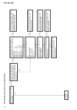
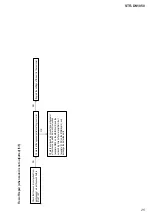
Flow of Repair (when sound is not outputted) (2/5)
Press the [A.F.D.] button to
select the “MULTI ST”, and
check that the sound by various
source (example: coaxial input,
analog input) is outputted from
all the channels (FL/FR/SL/SR/
SBL/SBR/C/SW).
Check that sound occurs from the RY921 on
the MAIN board by inserting and removing
headphone.
Check the following parts and the surrounding circuit,
and exchange the defective parts.
DIGITAL board: IC2100 HP board: J101
MAIN board: Q375, RY921
Check the following parts and the
surrounding circuit, and exchange the
defective parts.
DIGITAL board: IC2100, IC2502, IC2503, X2500
Check the following parts and the surrounding
circuit, and exchange the defective parts.
DIGITAL board: IC2100, IC2107, X2102
Check the following parts and the surrounding
circuit, and exchange the defective parts.
DCDC board: IC1907, IC1909
DIGITAL board: IC2500
Check that voltage of pins of the IC2502
on the DIGITAL board is the following value.
pin 4 : 1.12 V ~ 1.2 V pin 8 : 3.3 V
Check that data is outputted from the following pins.
DIGITAL board: IC2107 pin 16, 19, 20, 21
Check the following parts and the surrounding circuit,
and exchange the defective parts.
DIGITAL board: IC2100, IC2501, IC2502
Check the following parts and the surrounding circuit,
and exchange the defective parts.
DIGITAL board: IC2100, IC2104
Check the following parts and the surrounding circuit,
and exchange the defective parts.
DIGITAL board: IC2100
MAIN board: IC421
Perform the “SOFTWARE VERSION DISPLAY
MODE” (refer to pa
ge 17 on
the original service
manual), and check that the DSP version is not “0.00”.
Press the [MUTING] button on the remote
commander once, and check that the sound is
outputted from this unit.
Explain the settings of this unit to the customer.
Check that data is outputted from the following
pins.
DIGITAL board: IC2502 pin 73, 86, 88, 94
Check that data is outputted from the following
pins.
DIGITAL board: IC2104
pin 15, 16, 19, 20, 21, 22, 26, 27
Check that data is inputted to the following
pins.
MAIN board: IC421
pin 63, 64, 66 ~ 73
Check the surrounding circuit of power
transistor (example: Q600 on the MAIN board)
and the surrounding circuit of power amplifier
circuit (example: FL on the MAIN board), and
exchange the defective parts.
OK
– Continued on page 23 –
OK
NG
NG
NG
NG
NG
NG
NG
NG
NG
OK
OK
OK
OK
OK
OK
OK


