background image

37

GB

G

e

tting Star

te

d

2

Press 1 or 2 while the RM SET UP 
button is flashing.

When you press 1, the command mode is 
set to AV SYSTEM 1. When you press 2, 
the command mode is set to AV SYSTEM 
2.

3

Press ENTER when the RM SET UP 
button lights up.

The RM SET UP button flashes twice, then 
the command mode setting process is 
completed.

Tip

When you press RM SET UP, use a thin wire, such 
as a paper clip.

7: Operating the receiver 
using the GUI 

(Graphical User 

Interface)

By using the GUI menu, you can make various 
settings and adjustments.

1

Connect a TV monitor to this 
receiver.

Refer to “3: Connecting the monitor” 
(page 18)
.

2

Turn on the receiver and the TV.

3

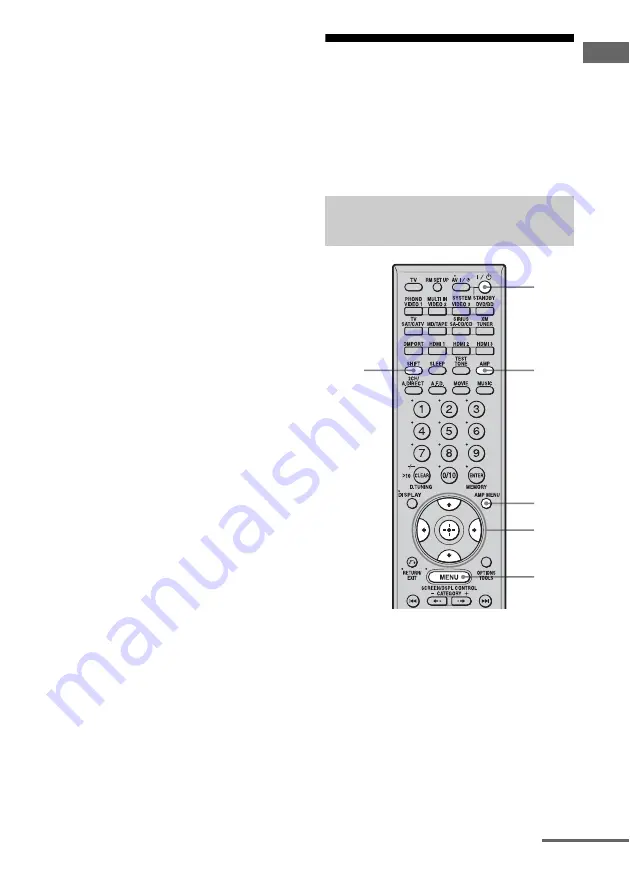
Press AMP to enable receiver 
operation.

Displaying the GUI menu on the 
TV screen

5

3

AMP 
MENU

4

2

4

continued

Summary of Contents for STR-DG1100

Page 1: ...Channel AV Receiver Operating Instructions Owner s Record The model and serial numbers are located on the rear of the unit Record the serial number in the space provided below Refer to them whenever you call upon your Sony dealer regarding this product Model No Serial No STR DG1100 ...

Page 2: ...ful interference in a residential installation This equipment generates uses and can radiate radio frequency energy and if not installed and used in accordance with the instructions may cause harmful interference to radio communications However there is no guarantee that interference will not occur in a particular installation If this equipment does cause harmful interference to radio or televisio...

Page 3: ...This product using Neural Surround THX Technologies is manufactured under license from Neural Audio Corporation and THX Ltd Sony Corporation hereby grants the user a non exclusive non transferable limited right to use this product and other related technologies dully licensed owned by Neural Audio Corporation and or THX Ltd following US and foreign patent and patent pending laws Neural Surround is...

Page 4: ...HDMI menu 56 Settings for the system System settings menu 57 Enjoying Surround Sound Enjoying a pre programmed sound field 58 Adjusting the sound effect 62 Using the surround back decoding mode 64 Enjoying the surround effect at low volume levels NIGHT MODE 66 Advanced Speakers Setting Up Adjusting the speaker settings manually 67 Adjusting the equalizer 73 Tuner Operations Listening to FM AM radi...

Page 5: ...5GB Additional Information Glossary 116 Precautions 118 Troubleshooting 119 Specifications 123 Index 126 ...

Page 6: ...of reach from children Status of the POWER button Off The receiver is turned off initial setting Press POWER to turn the receiver on You cannot turn the receiver on using the remote On Standby Press 1 on the remote to turn the receiver on or set it to the standby mode When you press POWER on the receiver the receiver will be turned off ...

Page 7: ... window The current status of the selected component or a list of selectable items appears here page 96 J 2CH A DIRECT Press to select sound field page 58 A F D MOVIE MUSIC K INPUT MODE Press to select the input mode when the same components are connected to both digital and analog jacks page 92 L MUTING Press to turn off the sound temporarily Press the button again to restore the sound M DMPORT P...

Page 8: ...8GB S INPUT SELECTOR Turn to select the input source to play back T MASTER VOLUME Turn to adjust the volume level of all speakers at the same time Name Function ...

Page 9: ...lite tuner An image and the sound are output to TV or a projector page 18 26 B ANTENNA section FMANTENNA jack Connects to the FM wire antenna aerial supplied with this receiver page 34 AM ANTENNA jack Connects to the AM loop antenna aerial supplied with this receiver page 34 XM jack Connects to the XM Mini Tuner and Home Dock not supplied page 79 SIRIUS jack Connects to a SiriusConnect Home tuner ...

Page 10: ...ner page 18 28 29 E AUDIO INPUT OUTPUT section AUDIO IN OUT jacks Connect to a tape deck or MD deck etc page 18 20 21 24 MULTI CHANNEL INPUT jacks Connect to a Super Audio CD player or DVD player with an analog audio jack for 7 1 channel or 5 1 channel sound page 20 23 PRE OUT jack Connects to an active sub woofer F VIDEO AUDIO INPUT OUTPUT section AUDIO IN OUT jacks Connect to a VCR or a DVD play...

Page 11: ... input button C B 1 on standby Press to turn the receiver on or off To turn off all components press 1 and AV 1 A at the same time SYSTEM STANDBY C Input buttons Press one of the buttons to select the component you want to use Press a pink labeled button after pressing SHIFT wj When you press any of the input buttons the receiver turns on The buttons are factory assigned to control Sony components...

Page 12: ...of the menu between SCREEN to display the menu on the TV screen and DSPL to display the menu in the display window N CATEGORY Press to select the category for satellite tuner page 109 Name Function O m M a x a X a H a b a Press to operate the DVD player Blu ray Disc Player CD player MD deck tape deck or component connected to the DIGITAL MEDIA PORT adapter etc CATEGORY MODE Press to select the cat...

Page 13: ...p a disc when using a multi disc changer V RETURN EXIT O Press to return to the previous menu or exit the menu while the menu or on screen guide of the VCR DVD player or satellite tuner is displayed on the TV screen W DISPLAY Press to select information displayed in the display window TV screen of the VCR satellite tuner CD player DVD player Blu ray Disc Player or MD deck Note In the SCREEN mode p...

Page 14: ...peaker DSurround left speaker ESurround right speaker HSub woofer You can enjoy high fidelity reproduction of DVD software recorded sound in the Surround EX format if you connect one additional surround back speaker 6 1 channel system or two surround back speakers 7 1 channel system See Using the surround back decoding mode page 64 Example of a 7 1 channel speaker system configuration AFront left ...

Page 15: ... angle A should be the same When you connect a 6 1 channel speaker system place the surround back speaker behind the seating position Since the sub woofer does not emit highly directional signals you can place it wherever you want ...

Page 16: ... R FSurround back speaker L b GSurround back speaker R b HSub wooferc a If you have an additional front speaker system connect them to the FRONT SPEAKERS B terminals You can select the front speaker system you want to use with the SPEAKERS switch OFF A B A B on the front panel page 41 H G F B A D E C A B FRONT SPEAKERS B terminals a AMonaural audio cord not supplied BSpeaker cords not supplied ...

Page 17: ...tandby mode automatically based on the level of the input signal to a sub woofer then sound may not be output Notes When you connect all the speakers with a nominal impedance of 8 ohms or higher set Impedance in the Speaker settings menu to 8 Ω In other connections set it to 4 Ω For details see 8 Setting the speakers page 40 Before connecting the AC power cord mains lead make sure that metallic wi...

Page 18: ...r using a GUI Graphical User Interface It is not necessary to connect all the cables Connect audio and video cords according to the jacks of your components TV monitor A B AOptical digital cord not supplied BAudio cord not supplied CVideo cord not supplied DHDMI cable not supplied EComponent video cord not supplied Audio signals C D E Video signals ...

Page 19: ... on the status of the connection between the TV and the antenna aerial the image on the TV screen may be distorted In this case place the antenna aerial farther away from the receiver Tips The receiver has a video conversion function For details see Notes on converting video signals page 32 The sound of the TV is output from the speakers connected to the receiver if you connect the sound output ja...

Page 20: ...the jacks of your components Notes When connecting optical digital cords insert the plugs straight in until they click into place Do not bend or tie optical digital cords Tip All the digital audio jacks are compatible with 32 kHz 44 1 kHz 48 kHz and 96 kHz sampling frequencies How to hook up your components Component to be connected Page Super Audio CD player CD player With digital audio output 21...

Page 21: ...AC power cord mains lead To disconnect the DIGITAL MEDIA PORT adapter remove the cable by squeezing the sides of the connector since the connector is locked in place Connecting components with digital audio input output jacks Super Audio CD player CD player MD deck A B A AAudio cord not supplied BCoaxial digital cord not supplied COptical digital cord not supplied C DIGITAL MEDIA PORT adapter cont...

Page 22: ...er to the MULTI CHANNEL INPUT or SA CD CD IN jacks Refer to the operating instructions supplied with the Super Audio CD player You cannot make digital recordings of a Super Audio CD When connecting optical digital cords insert the plugs straight in until they click into place Do not bend or tie optical digital cords If you want to connect several digital components but cannot find an unused input ...

Page 23: ...necting cords make sure to disconnect the AC power cord mains lead DVD and Super Audio CD players do not have the SURROUND BACK jacks When Sur Back Assign is set to BI AMP in the Speaker settings menu the input to the SUR BACK jacks is invalid Audio input signals from MULTI CHANNEL INPUT jacks are not output to any audio output jacks The signals cannot be recorded Connecting components with multi ...

Page 24: ...ble etc Notes If your turntable has a ground earth wire connect it to the U SIGNAL GND terminal Before connecting cords make sure to disconnect the AC power cord mains lead Connecting components with analog audio jacks Super Audio CD player CD player Turntable A MD deck Tape deck A AAudio cord not supplied A ...

Page 25: ...oceed to 5 Connecting the antennas aerials page 34 The image quality depends on the connecting jack Refer to the illustration that follows Select the connection according to the jacks on your components How to hook up your components Component to be connected Page TV monitor 18 With HDMI jack 26 DVD player Blu ray Disc Player 28 Satellite tuner CATV system 29 DVD recorder VCR 30 Camcorder video ga...

Page 26: ... to the VIDEO jack or COMPONENT VIDEO jacks can be output as HDMI signals Audio signals are not output from an HDMI OUT jack when the image is converted This receiver supports xvYCC transmission This receiver supports the HDMI CONTROL function Refer to HDMI CONTROL Guide supplied with the receiver Connecting components with HDMI jacks DVD player Satellite tuner Blu ray Disc Player PS3 hard disk re...

Page 27: ...TOR VIDEO OUT jacks The audio and video signals of HDMI input are not output from the HDMI OUT jack while the receiver menu is displayed When you want to listen to the sound from the TV speaker set HDMI Audio to TV AMP in the HDMI settings menu If set to AMP the sound is not output from the TV speaker DSD signals of Super Audio CD are not input and output Be sure to turn on the receiver when video...

Page 28: ... Refer to the operating instructions supplied with the DVD player Blu ray Disc Player Before connecting cords make sure to disconnect the AC power cord mains lead When you connect a component equipped with an OPTICAL jack set Input Assign in the Input menu Connecting a DVD player Blu ray Disc Player DVD player Blu ray Disc Player A B C AOptical digital cord not supplied BCoaxial digital cord not s...

Page 29: ...d video cords according to the jacks of your components Note Before connecting cords make sure to disconnect the AC power cord mains lead Connecting a satellite tuner CATV system Satellite tuner CATV system A B C D AOptical digital cord not supplied BAudio cord not supplied CVideo cord not supplied DComponent video cord not supplied Audio signals Video signals ...

Page 30: ...eo cords according to the jacks of your components Connecting components with analog video and audio jack DVD recorder VCR A To the VIDEO 3 IN PORTABLE AV IN jacks Front panel B C AAudio cord not supplied BVideo cord not supplied CAudio video cord not supplied Audio signals Video signals Camcorder video game Note Before connecting cords make sure to disconnect the AC power cord mains lead ...

Page 31: ...ersion table classified by the menu settings page 33 In the video input output conversion table of the receiver a Video signals are converted and output through the video converter f The same type of signal as that of the input signal is output Video signals are not converted X Video signals are not output Video signals are output when Resolution is set to DIRECT in the Video settings menu Functio...

Page 32: ...resolution of video signals protected by copyright technology is converted Resolution of up to 480p can be output to the COMPONENT VIDEO MONITOR OUT jacks The HDMI OUT jack has no restriction on resolution Video signals for which the resolution has been converted cannot be output from either the COMPONENT VIDEO MONITOR OUT jacks or the HDMI OUT jack The video signals are output from the HDMI OUT j...

Page 33: ...s set d Video signals without copyright protection are output based on the settings menu Video signals with copyright protection are output as 480p Notes Video signals are not output from the COMPONENT VIDEO MONITOR OUT or MONITOR VIDEO OUT jack when the monitor etc is connected to the HDMI OUT jack If you select a resolution that the connected TV does not support in the Resolution menu the images...

Page 34: ...s To prevent noise pickup keep the AM loop antenna aerial away from the receiver and other components Be sure to fully extend the FM wire antenna aerial After connecting the FM wire antenna aerial keep it as horizontal as possible Before connecting cords make sure to disconnect the AC power cord mains lead FM wire antenna aerial supplied AM loop antenna aerial supplied ...

Page 35: ...e stated on the rear panel Do not connect high wattage electrical home appliances such as electric irons fans or TVs to this outlet This may cause a malfunction Before using the receiver for the first time initialize the receiver by performing the following procedure This procedure can also be used to return settings you have made to their factory defaults 1 Press POWER to turn off the receiver 2 ...

Page 36: ...mmand modes of the receiver and the remote are different you cannot use the remote to operate the receiver If the command modes of both the receiver and the remote are those of the initial setting AV SYSTEM 2 it is not necessary to reset them You can switch the command mode AV SYSTEM 1 or AV SYSTEM 2 of the receiver and the remote If both the receiver and the other Sony component respond to the sa...

Page 37: ...hen the command mode setting process is completed Tip When you press RM SET UP use a thin wire such as a paper clip 7 Operating the receiver using the GUI Graphical User Interface By using the GUI menu you can make various settings and adjustments 1 Connect a TV monitor to this receiver Refer to 3 Connecting the monitor page 18 2 Turn on the receiver and the TV 3 Press AMP to enable receiver opera...

Page 38: ...brating the appropriate speaker settings automatically Auto Calibration page 42 Speaker You can use the Speaker settings menu to adjust the speakers manually for the current position and to set the speaker impedance For details see Setting the speaker impedances page 40 and Adjusting the speaker settings manually page 67 Surround You can use the Surround settings menu to select the sound field you...

Page 39: ... the GUI menu on the TV screen page 37 2 Press MENU repeatedly to display the GUI menu on the TV screen 3 Press V v repeatedly to select a menu you want 4 Press or b to enter the menu The menu item list appears on the TV screen 5 Press V v repeatedly to select the menu item you want to adjust 6 Press or b to enter the menu item 7 Repeat steps 3 to 6 to select the parameter you want To return to th...

Page 40: ...r then press or b 4 Press V v repeatedly to select Impedance then press 5 Press V v repeatedly to select 4 Ω or 8 Ω depending on the speakers you are using then press Notes If you are not sure of the impedances of the speakers refer to the operating instructions supplied with your speakers This information is often on the back of the speaker When you connect all speakers with a normal impedance of...

Page 41: ...o drive Set the SPEAKERS switch to select the front speaker system you want to drive Note This setting is not available when headphones are connected Selecting the front speakers Set to To select A The speakers connected to the FRONT SPEAKERS A terminals B The speakers connected to the FRONT SPEAKERS B terminals A B The speakers connected to both the FRONT SPEAKERS A and B terminals parallel conne...

Page 42: ...ore accurate measurement If there are any obstacles in the path between the optimizer microphone and the speakers the calibration cannot be performed correctly Remove any obstacle from the measurement area to avoid measurement error When you use a bi amplifier connection set Sur Back Assign to BI AMP in the Speaker settings menu before you perform auto calibration Notes The auto calibration functi...

Page 43: ...ction is invalid for other speakers b The measurement result is not utilized when the multi channel input is selected c DTS 96 24 signals are always played back as 48 kHz when you correct signals The measurement result is not utilized in the following cases The multi channel input is selected 2ch Analog Direct is being used Input signals of which the sampling frequency is more than 96 kHz are bein...

Page 44: ...in the Speaker settings menu Tips Operations other than turning the receiver on or off are deactivated during the measurement When connecting special speakers such as dipole speakers the measurements have not been performed correctly or auto calibration cannot be performed To cancel the measurement The measurement is cancelled when you change the volume switch functions change the setting of the S...

Page 45: ...ct Yes For details on warning and error codes see Message list after auto calibration measurement page 47 Tip Press on the remote when Please Press ENTER appears on the TV screen 3 Press B b repeatedly to select Yes then press 4 Press V v repeatedly to select the auto calibration type then press b The measurement results are saved 5 Press The exit screen appears Notes DTS 96 24 signals are played ...

Page 46: ...s may vary depending on the position of the optimizer microphone and speakers and the shape of the room It is recommended that you follow the measurement results However you can change those settings in the Speaker settings menu Save the measurement results first then try to change the settings if you want ...

Page 47: ...one front speaker is connected The optimizer microphone is not connected Either the left or right surround speakers is not connected Surround back speakers are connected even though surround speakers are not connected Connect the surround speaker s to the SURROUND terminals The surround back speaker is connected only to the SURROUND BACK SPEAKERS R terminals When you connect only one surround back...

Page 48: ...e patterns as position 1 2 and 3 depending on the seating position listening environment and measurement conditions Calibration Type For details see the table on page 45 Optional menu parameters for Enhanced Setup settings EQ Curve Activates deactivates the EQ curve measurement Name Input You can rename the position number for details refer to Naming inputs page 91 ...

Page 49: ...onnected to the VIDEO 1 or VIDEO 2 jack VIDEO 3 Video camera and TV game etc connected to the VIDEO 3 jack DVD BD DVD player Blu ray Disc Player etc connected to the DVD BD jack SAT CATV Satellite tuner etc connected to the SAT CATV jack MD TAPE MD or tape deck etc connected to the MD TAPE jack SA CD CD Super Audio CD or CD player etc connected to the SA CD CD jack TUNER Built in radio tuner DMPOR...

Page 50: ...up or down quickly press and hold the button To make a fine adjustment press the button and release it immediately To activate the muting function Press MUTING on the remote To cancel press MUTING on the remote again or turn MASTER VOLUME clockwise to raise the volume Even if you turn off the receiver the muting function works when you turn the receiver on again To avoid damaging your speakers Bef...

Page 51: ...ended sound fields Classical Hall Jazz Jazz Club Live concert Live Concert Stadium 1 Turn on the Super Audio CD player or CD player then place the disc in the tray 2 Turn on the receiver 3 Press SA CD CD You can also use INPUT SELECTOR on this receiver to select SA CD CD An example of the display 4 Play back the disc 5 Adjust to a suitable volume 6 After you have finished listening to a Super Audi...

Page 52: ...ormat the MULTI CHANNEL DECODING lamp on the front panel lights up during playback Be sure this receiver is connected to the DVD player Blu ray Disc Player via a digital connection Be sure the digital audio output of the DVD player Blu ray Disc Player is set up properly 1 Turn on the TV and DVD player or Blu ray Disc Player 2 Turn on the receiver 3 Press DVD BD You can also use INPUT SELECTOR on t...

Page 53: ...UT SELECTOR on this receiver to select VIDEO 3 When you connect a TV game to the VIDEO 3 IN PORTABLE AV IN jack on the front panel An example of the display 4 Switch the input of the TV so that an image of the video game is displayed 5 Place the disc in the tray and play it back on the video game 6 Adjust to a suitable volume 7 After you have finished playing a game eject the disc and turn off the...

Page 54: ... also use INPUT SELECTOR on this receiver to select VIDEO 1 When you connect VCR to the VIDEO 1 jack An example of the display 4 Switch the input of the TV so that an image of the VCR is displayed 5 Play back the tape on the VCR 6 Adjust to a suitable volume 7 After you have finished a watching video eject the tape and turn off the receiver the TV and the VCR ...

Page 55: ...THX is selected as the sound field type x Dual Mono Digital broadcast language selection Lets you select the language you want to listen to during a digital broadcast This feature only functions for Dolby Digital sources MAIN SUB Sound of the main language will be output through the front left speaker and sound of the sub language will be output through the front right speaker simultaneously MAIN ...

Page 56: ...ents connected to the HDMI jack using an HDMI cable on or off ON OFF Note When you set HDMI Control to ON HDMI Audio may be changed automatically x HDMI Audio Setting HDMI audio input Lets you set the HDMI audio signals output from the playback component connected to the receiver via an HDMI connection TV AMP The sound is output from TV s speaker and the speakers connected to the receiver Notes Th...

Page 57: ... or 10 dB depending on the frequency 10 dB Settings for the system System settings menu You can use the System settings menu to customize the settings of the receiver Select System in the Settings menus For details on adjusting the parameters see 7 Operating the receiver using the GUI Graphical User Interface page 37 x Screen Saver Lets you activate the screen saver function for the GUI menu on th...

Page 58: ...ings menu that can be used to make advanced adjustments For details see Adjusting the sound effect page 62 x 2ch Stereo The receiver outputs the sound from the front left right speakers only There is no sound from the sub woofer Standard 2 channel stereo sources completely bypass the sound field processing and multi channel surround formats are downmixed to 2 channel Note No sound is output from t...

Page 59: ... Music 5 channel signals Performs Dolby Pro Logic II Music mode decoding This setting is ideal for normal stereo sources such as CDs PLII Game 5 channel signals Performs Dolby Pro Logic II Game mode decoding PLIIx Movie 7 channel signals Performs Dolby Pro Logic IIx Movie mode decoding This setting is ideal for movies encoded in Dolby Surround In addition this mode can reproduce sound in 7 1 chann...

Page 60: ...ay be better to use SB Decoding to match the input stream to the mode you prefer You can identify the encoding format of DVD software etc by looking at the logo on the package Dolby Pro Logic IIx decoding is effective when a multi channel signal is input At this time the setup of SB Decoding and SB Dec Mode in the Surround settings menu becomes invalid When you select decoding modes other than Dol...

Page 61: ...tual speakers from a single pair of actual surround speakers Music Hall Reproduces the acoustics of a classical concert hall Jazz Club Reproduces the acoustics of a jazz club Live Concert Reproduces the acoustics of a 300 seat live house Stadium Reproduces the feeling of a large open air stadium Sports Reproduces the feeling of sports broadcasting Portable Audio Reproduces a clear enhanced sound i...

Page 62: ...or music is selected no sound is output from the sub woofer if all the speakers are set to LARGE in the Speaker settings menu However the sound will be output from the sub woofer if the digital input signal contains L F E signals or if the front or surround speakers are set to SMALL the sound field for movie is selected or Portable Audio is selected Tips Sound fields with DCSmarks use DCS technolo...

Page 63: ...ode decoding You can set this parameter only when A F D mode is set to PLII Music or PLIIx Music You can adjust the difference between the front channels and the surround channels x Panorama Mode Lets you perform further adjustments for Dolby Pro Logic II and IIx Music mode decoding You can set this parameter only when A F D mode is set to PLII Music or PLIIx Music ON Lets you enjoy surround sound...

Page 64: ...ce page 37 2 Press V v repeatedly to select Settings then press or b The Settings menu list appears on the TV screen 3 Press V v repeatedly to select Surround then press or b 4 Press V v repeatedly to select SB Dec Mode then press 5 Press V v repeatedly to select the surround back decoding mode then press Tip You can select the surround back decoding mode using SB Decoding on the Surround settings...

Page 65: ...Dolby Digital EX logos In this case select ON When PLIIx of the A F D mode is selected the SB Decoding is decoded in the PLIIx mode x SB Dec Mode Surround back decoding mode You can select surround back decoding mode only when SB Decoding is set to ON or AUTO and the input stream contains the Dolby Digital Surround EX flag Note Matrix decoding conforming to Dolby Digital EX is applied if the speak...

Page 66: ...is enabled 2 Press NIGHT MODE The NIGHT MODE function is activated The NIGHT MODE is set to on and off as you press NIGHT MODE Notes This function does not work in the following cases The multi channel input is selected Input signals of which the sampling frequency is more than 96 kHz are being received If you set the NIGHT MODE to ON during DTS 96 24 signal reception the signal will be played bac...

Page 67: ...hen press 4 Press V v repeatedly to select Manual Setup then press x Level Level of speaker You can adjust each speaker s level center surround left right surround back left right sub woofer You can adjust the level from 20 dB to 10 dB in 0 5 dB steps For the front left right speakers you can adjust the balance on either side You can adjust the front left level from FL 10 0 dB to FL 10 0 dB in 0 5...

Page 68: ...r determine whether the internal sound processor will cut the bass signal from that channel When the bass is cut from a channel the bass redirection circuitry sends the corresponding bass frequencies to the sub woofer or other LARGE speakers However since bass sound has a certain amount of directionality it is best not to cut it if possible Therefore even when using small speakers you can set them...

Page 69: ...le However if the speakers are pointing toward the listener from the immediate left and right of the seating position the surround effects become unclear unless set to SIDE Nevertheless each listening environment has many variables such as wall reflections and you may obtain better results using BEHD if your speakers are located high above the seating position even if they are located to the immed...

Page 70: ...ern according to the speaker system which you are using You do not need to select the speaker pattern after auto calibration 5 Press V v repeatedly to select the speaker pattern you want 1 Make sure that the AMP button is lit If it is not lit or GUI MODE is not displayed in the display window of the receiver follow the steps given in 7 Operating the receiver using the GUI Graphical User Interface ...

Page 71: ... speaker connection and the speaker pattern match x Test Tone OFF AUTO The test tone is output from each speaker in sequence FIX You can select which speakers will output the test tone x Phase Noise OFF L R L C C R R SL R SR SR SL SR SBR SBR SBL SR SB SBL SL SB SL SL L L SR Lets you output the test tone sequentially from adjacent speakers Some items may not be displayed depending on the setting of...

Page 72: ...PUT jacks The sub woofer level from DVD players is 10 dB lower than that of Super Audio CD players x D Range Comp Dynamic range compressor Lets you compress the dynamic range of the sound track This may be useful when you want to watch movies at low volumes late at night Dynamic range compression is possible with Dolby Digital sources only OFF The dynamic range is not compressed STD The dynamic ra...

Page 73: ... not displayed in the display window of the receiver follow the steps given in 7 Operating the receiver using the GUI Graphical User Interface page 37 2 Press V v repeatedly to select Settings then press or b The Settings menu list appears on the TV screen 3 Press V v repeatedly to select EQ then press 4 Press V v repeatedly to select the preset number that you want to register as the number to st...

Page 74: ...74GB Clearing stored equalizer settings 1 Press OPTIONS then press Are you sure to clear EQ Settings appears 2 Press B b repeatedly to select Yes then press ...

Page 75: ... is not displayed in the display window of the receiver follow the steps given in 7 Operating the receiver using the GUI Graphical User Interface page 37 2 Press V v repeatedly to select FM or AM then press or b The FM or AM menu list appears on the TV screen 3 Press V v to select Auto Tuning then press 4 Press V v Press V to scan from low to high press v to scan from high to low The receiver stop...

Page 76: ...o select Direct Tuning then press 4 Press the numeric buttons to enter the frequency then press to enter Example 1 FM 102 50 MHz Select 1 b 0 b 2 b 5 Example 2 AM 1 350 kHz Select 1 b 3 b 5 b 0 Tip If you have tuned in an AM station adjust the direction of the AM loop antenna aerial for optimum reception If you cannot tune in a station MHz appears and then the display returns to the current freque...

Page 77: ...e 76 In case of poor FM stereo reception switch the FM reception mode page 75 4 Press OPTIONS 5 Press V v to select Memory then press to enter 6 Press V v to select a preset number 7 Press The station is stored as the selected preset number 8 Repeat steps 3 to 7 to preset another station To tune to preset stations 1 Repeat steps 1 and 2 of Presetting radio stations 2 Press V v to select the preset...

Page 78: ...eiving XM programming There are three places to find your eight character XM Radio ID on the XM Mini Tuner on the XM Mini Tuner package and on XM Channel 0 Record the Radio ID in the following eight squares for reference ssssssss Note The XM Radio ID does not use the letters I O S or F Activate your XM Satellite Radio service in the U S online at http activate xmradio com or call 1 800 XMRADIO 1 8...

Page 79: ...uth facing window with a clear view to the sky To connect to the SIRIUS jack Connect the SiriusConnect Home Tuner When you use the SiriusConnect Home Tuner with this receiver be sure to connect the AC power adaptor supplied with the tuner to a wall outlet Keep the SiriusConnect Home Tuner antenna and AC power adaptor away from the speaker cords and the power cord to avoid picking up noise 1 Make s...

Page 80: ...he TV screen and write it in the space provided here XM Radio ID _____________________ Sirius ID _________________________ You can also check the XM Radio ID and Sirius ID using the display on the receiver You can select a channel from one category or all the categories XM SIRIUS XM SIRIUS Selecting a channel by Category Mode 1 2 4 ...

Page 81: ...ry Mode 4 Press V v to select the channel then press The selected channel is being received The channel information is displayed on the TV screen Note When you select a channel in the Category Mode the channel you selected may not be the one in the category you want This is because one channel may belong to more than one category 1 Make sure that the AMP button is lit If it is not lit or GUI MODE ...

Page 82: ...o select Memory then press to enter 6 Press V v repeatedly to select the preset channel you want to use as the preset channel then press Preset channels from 1 to 30 are available and a default channel is preset for all the preset channels when you purchase the receiver The selected channel is registered as the preset channel you selected in step 3 7 Repeat steps 3 to 6 to preset another channel T...

Page 83: ...age 37 2 Press V v repeatedly to select SIRIUS then press or b 3 Select a channel you want to lock using Category Tuning page 80 or Direct Tuning page 81 4 Press OPTIONS then press V v to select Parental Lock then press or b 5 Press V v repeatedly to select ON then press Enter your 4 digit lock code appears 6 Enter your 4 digit lock code using the number buttons The channel has been locked appears...

Page 84: ...k code using the number buttons The channel is tuned in To cancel the Parental Lock 1 Press V v repeatedly to select SIRIUS then press or b 2 Tune in the channel you want to unlock using Direct Tuning page 81 3 Press OPTIONS then press V v to select Parental Lock then press or b 4 Press V v repeatedly to select OFF then press Enter your 4 digit lock code appears 5 Enter your 4 digit lock code usin...

Page 85: ... The selected channel is not available Message appears Explanation Remedies Antenna Error The antenna is not connected properly Check the connection between the SiriusConnect Home tuner and the antenna Acquiring Signal The receiving condition is not good Try moving the antenna to another location For details about the antenna location see the instructions supplied with the SiriusConnect Home tuner...

Page 86: ...ware is being updated There is no text information in the channel This is not an error The text information may not be displayed depending on the system condition for example right after the system has received a channel Message appears Explanation Remedies ...

Page 87: ...ary in each area For details on connecting the DIGITAL MEDIA PORT adapter see Connecting components with digital audio input output jacks page 21 Sony offers the following DIGITAL MEDIA PORT adapters TDM BT1 Bluetooth Wireless Audio Adapter TDM NW1 DIGITAL MEDIA PORT Adapter TDM NC1 Wireless Network Audio Client TDM iP1 DIGITAL MEDIA PORT Adapter The DIGITAL MEDIA PORT adapter is an optional produ...

Page 88: ...e component connected to DIGITAL MEDIA PORT adapter appears on the screen Note An icon which shows the component recognized is displayed on the TV screen If the adapter connected cannot be recognized DMPORT is displayed on the TV screen 5 Press OPTIONS to display Function List 6 Press V v to select DMPORT Control You can select the following modes in this menu System GUI This mode is for the TDM i...

Page 89: ... details on operating the adapter using the adapter GUI menu refer to the operating instructions supplied with the adapter you are using To operate the TDM iP1 using the iPod menu Make sure that iPod is selected in step 6 in Selecting an operation screen to operate the component connected to the DIGITAL MEDIA PORT adapter page 88 For details on operating the iPod refer to the operating instruction...

Page 90: ...llowing Play Press H Pause Press X To resume play press the button again Stop Press x Find the beginning of a track during playback or find the beginning of the previous track Press Find the beginning of the next track Press Skip to the previous album Press B Skip to the next album Press b Go backward forward Press m M Message appears Explanation No Adapter The adapter is not connected No Device T...

Page 91: ...ts 1 Choose the item you want to name You can name the following items Auto calibration position page 42 Inputs page 49 Preset stations page 77 2 Press OPTIONS 3 Select Name Input then press The soft keyboard appears on the screen 4 Press V v B b to select a character then press 5 Press Finish to enter the name The name you entered is registered To cancel naming input Press Cancel 2 3 4 ...

Page 92: ...o Gives priority to digital audio signals when there are both digital and analog connections If there are no digital audio signals analog audio signals are selected Analog Specifies the analog audio signals input to the AUDIO IN L R jacks Notes Some audio input modes may not be set up depending on the input When eitherHDMIinput satellitetuner or DIGITAL MEDIA PORT adapter is selected appears on th...

Page 93: ...Assign video and or audio signals to the DVD BD input jack using Input Assign in the Input menu 1 Make sure that the AMP button is lit If it is not lit or GUI MODE is not displayed in the display window of the receiver follow the steps given in 7 Operating the receiver using the GUI Graphical User Interface page 37 2 Press MENU repeatedly to display the GUI menu on the TV screen 3 Press V v repeat...

Page 94: ...audio input to the same input You cannot reassign more than one component video input to the same input Input name VIDEO1 VIDEO2 VIDEO3 DVD BD SAT CATV MD TAPE SA CD CD Assignable video input jacks Video1 Component a a a a a Video1 Composite a Video2 Composite a Video3 Composite a DVD BD Component a a a a a DVD BD Composite a SAT CATV Component a a a a a SAT CATV Composite a HDMI1 a a a a a a a HD...

Page 95: ...elected t Original input name t Sound field type t Volume Tip You cannot switch the display while GUI MODE is shown on the display Press SHIFT then press MENU to cancel the GUI display mode FM and AM band Station name t Frequency t Sound field type t Volume Index name appears only when you have assigned one to the input or preset station Index name does not appear when only blank spaces have been ...

Page 96: ... SB The letters L C R etc indicate the channels being played back The boxes around the letters vary to show how the receiver downmixes the source sound based on the speaker settings Front Left Front Right Center monaural Surround Left Surround Right Surround monaural or the surround components obtained by Pro Logic processing Surround Back Left Surround Back Right Surround Back the surround back c...

Page 97: ...hannel input is selected L XM Lights up when XM Mini Tuner and Home Dock are connected and XM is selected Name Function M D RANGE Lights up when dynamic range compression is activated N EQ Lights up when the equalizer is activated O SIRIUS Lights up when the SiriusConnect Home tuner is connected and SIRIUS is selected P D C A C Lights up when auto calibration is activated Q SLEEP Lights up when th...

Page 98: ...inema Music decoding is activated W MATRIX Lights up when DTS ES Matrix decoding is activated X SB DEC Lights up when surround back sound decoding is activated Y DISCRETE Lights up when DTS ES Discrete decoding is activated Z Tuner indicators Lights up when using the receiver to tune in radio stations etc Name Function wj PRESET Lights up when the tuning mode is set to the preset mode wk MEMORY Li...

Page 99: ... record from a video audio component using the receiver Refer to the operating instructions supplied with your recording component You can record onto a MiniDisc or audio tape using the receiver See the operating instructions supplied with your MD deck or tape deck 1 Press the input button of the playback component 2 Prepare the playback component for playing For example insert a CD into the CD pl...

Page 100: ...PUT jacks are not output Only analog input signals are output from the analog output jack for recording Only digital input signals are output from the digital output jack for recording HDMI sound cannot be recorded Using a bi amplifier connection If you are not using surround back speakers you can use the SURROUND BACK SPEAKERS terminals for the front speakers for use with a bi amplifier connectio...

Page 101: ...speaker level balance and equalizer settings of the surround back speakers become invalid and those of the front speakers are used Operating without connecting to the TV You can operate this receiver using the display even if you do not use a GUI when a TV monitor is not connected Press SHIFT then press MENU to display DISPLAY in the display window When GUI MODE is displayed in the display window ...

Page 102: ...O L to SW FIX OFF PHASE NOISE xxxxxxx OFF L C C R R SL R SR SR SL SR SBR SBR SBL SBL SL SL L L SR OFF PHASE AUDIO xxxxxxx OFF L C C R R SL R SR SR SL SR SBR SBR SBL SBL SL SL L L SR OFF FRONT L xxx x dB 10 0 dB to 10 0 dB 0 5 dB step 0 dB FRONT R xxx x dB 10 0 dB to 10 0 dB 0 5 dB step 0 dB CENTER xxx x dB 20 0 dB to 10 0 dB 0 5 dB step 0 dB SURROUND L xxx x dB 20 0 dB to 10 0 dB 0 5 dB step 0 dB ...

Page 103: ...0 SURROUND R xxxxxxxxx 3 3 to 32 9 1 inch step 9 10 SUR BACK xxxxxxxxx 3 3 to 32 9 1 inch step 9 10 SUR BACK L xxxxxxxxx 3 3 to 32 9 1 inch step 9 10 SUR BACK R xxxxxxxxx 3 3 to 32 9 1 inch step 9 10 SUB WOOFER xxxxxxxxx 3 3 to 32 9 1 inch step 9 10 DISTANCE UNIT xxxxx meter feet feet SP POSI xxxxxxxxx SIDE LOW SIDE HIGH BEHD LOW BEHD HIGH SIDE LOW FR CROSSOVER xxx Hz 40 Hz to 200 Hz 10 Hz step 12...

Page 104: ...T xxx OFF 1 2 3 4 5 1 FRONT BASS xxx dB 10 0 dB to 10 0 dB 1 dB step 0 dB FRONT TREBLE xxx dB 10 0 dB to 10 0 dB 1 dB step 0 dB CENTER BASS xxx dB 10 0 dB to 10 0 dB 1 dB step 0 dB CENTER TREBLE xxx dB 10 0 dB to 10 0 dB 1 dB step 0 dB SUR SB BASS xxx dB 10 0 dB to 10 0 dB 1 dB step 0 dB SUR SB TREBLE xxx dB 10 0 dB to 10 0 dB 1 dB step 0 dB PRESET x CLEAR xxx YES NO NO Tuner Settings FM MODE xxxx...

Page 105: ...xxxx SA CD Video Settings RESOLUTION xxxxxxxx DIRECT AUTO 480 576i 480 576p 720p 1080i 1080p AUTO COMPONENT V ASSIGN VIDEO 1 c xxxxxxxx NONE VIDEO1 to 3 DVD BD SAT CATV MD TAPE SA CD CD MULTI IN VIDEO1 DVD BD c xxxxxxxx DVD BD SAT CATV c xxxxxxxx SAT CATV HDMI Settings HDMI CONTROL xxx OFF ON OFF HDMI AUDIO xxxxxx AMP TV AMP AMP HDMI SW xxx dB 0dB 10dB AUTO AUTO HDMI VIDEO ASSIGN HDMI 1 c xxxxxxxx...

Page 106: ...urround back speakers Set this value from SP POSI settings in the Speaker settings menu Tips Operations other than turning the receiver on or off are deactivated during auto calibration When special speakers such as dipole speakers are used the measurements may not be performed correctly or auto calibration cannot be performed To confirm save auto calibration when GUI function is turned off 1 Conf...

Page 107: ...peatedly The selected sound field type appears on the display You can also use the 2CH A DIRECT A F D MOVIE or MUSIC buttons on the receiver Press 2CH A DIRECT You can also use 2CH A DIRECT on the receiver For details on the tuner function see Tuner Operations page 75 EXIT Exits the setting process without saving the measurement results AUTO EQ type Explanation FULL FLAT Makes the measurement of f...

Page 108: ...station is stored as the selected preset number If MEMORY disappears before you select the preset number start again from step 2 5 Repeat steps 1 to 4 to preset another station Selecting a preset station 1 Press TUNER repeatedly to select the FM or AM band 2 Press PRESET or PRESET repeatedly to select the preset station you want You can also press the numeric buttons to select the preset station y...

Page 109: ...aying the satellite tuner information Press DISPLAY repeatedly Each time you press DISPLAY while tuning in the channel the display changes cyclically as follows Channel name t Channel number t Category t Artist name t Song title t Composer name SIRIUS only t Sound field type 1 Select a channel you want to preset For details on this operation refer to Selecting channels from a category CATEGORY TUN...

Page 110: ...g Sony or non Sony components you can use the buttons on the remote that are marked with circles Note however that some buttons may not operate your component If you want to change the contents of the input list to match your particular components see Programming the remote page 112 Using the Remote ...

Page 111: ...ns z z z z z z z z z z z z z z MEMORY ENTER z z z z z z z z z z z z z CLEAR D TUNING 10 z z z z z z z z z z z z DISPLAY z z z z z z z z z z z OPTIONS TOOLS z z z z z RETURN EXIT z z z z z z z z z z z z V v B b z z z z z z z z z z z z z z z z z z z z z z MENU z z z z z z z z z z z z z z z z z z z z z z CATEGORY B b z z z z z z m TUNING M TUNING z z z z z z z z z z z z X x z z z z z z z z z z z H z ...

Page 112: ...ou are going to control a VCR connected to VIDEO 2 press VIDEO 2 RM SET UP and the input button light up If you press the button for a component of which you cannot program the remote such as DMPORT XM or SIRIUS etc the RM SET UP button keeps flashing 3 Press the numeric buttons to enter the numeric code or one of the codes if more than one code exists corresponding to the component and the maker ...

Page 113: ...ON 104 123 JVC 105 106 107 KENWOOD 108 109 110 MAGNAVOX 111 116 MARANTZ 116 ONKYO 112 113 114 PANASONIC 115 PHILIPS 116 PIONEER 117 TECHNICS 115 118 119 YAMAHA 120 121 122 Maker Code s SONY 203 PIONEER 219 Maker Code s SONY 301 DENON 302 JVC 303 KENWOOD 304 Maker Code s SONY 201 202 DENON 204 205 KENWOOD 206 207 208 209 NAKAMICHI 210 PANASONIC 216 PHILIPS 211 212 PIONEER 213 214 TECHNICS 215 216 Y...

Page 114: ...ER 409 TOSHIBA 404 DENON 405 Maker Code s SONY 403 Maker Code s SONY 501 502 DAEWOO 504 505 506 507 515 544 FISHER 508 GOLDSTAR LG 503 511 512 515 534 544 GRUNDIG 517 534 HITACHI 513 514 515 544 ITT NOKIA 521 522 JVC 516 Maker Code s MAGNAVOX 503 518 544 MITSUBISHI MGA 503 519 544 NEC 503 520 544 PANASONIC 509 524 PHILIPS 515 518 PIONEER 509 525 526 540 RCA PROSCAN 510 527 528 529 544 SAMSUNG 503 ...

Page 115: ...he remote s memory 1 Press and hold MASTER VOL first then press 1 then press AV 1 The RM SET UP button flashes three times 2 Release MASTER VOL All the contents of the remote s memory i e all the programmed data are cleared Maker Code s SONY 313 314 315 AV 1 1 MASTER VOL ...

Page 116: ...sover frequency The frequency at which two speaker s frequencies intersect x Digital Cinema Sound DCS Unique sound reproduction technology for home theater developed by Sony in cooperationwith Sony PicturesEntertainment for enjoying the exciting and powerful sound of movie theaters at home With this Digital Cinema Sound developed by integrating a DSP Digital signal processor and measured data the ...

Page 117: ...gh Definition Multimedia Interface HDMI High Definition Multimedia Interface is an interface that supports both video and audio on a single digital connection allowing you to enjoy high quality digital picture and sound The HDMI specification supports HDCP High bandwidth Digital Contents Protection a copy protection technology that incorporates coding technology for digital video signals x Interla...

Page 118: ...to the wall outlet even if the unit itself has been turned off If you are not going to use the receiver for a long time be sure to disconnect the receiver from the wall outlet To disconnect the AC power cord mains lead grasp the plug itself never pull the cord One blade of the plug is wider than the other for the purpose of safety and will fit into the wall outlet only one way If you are unable to...

Page 119: ... of the following difficulties while using the receiver use this troubleshooting guide to help you remedy the problem Should any problem persist consult your nearest Sony dealer Audio There is no sound no matter which component is selected or only a very low level sound is heard Check that the speakers and components are connected securely Check that all speaker cords are connected correctly Check...

Page 120: ...e the selected audio digital input jack is not assigned to other inputs in Input Assign in the Input menu page 93 The source sound input from the HDMI jack is not output from an amplifier or the TV speaker connected to the receiver Check that the component is connected correctly to the HDMI jack for that component The sound is not output when you display the receiver s menu on the TV monitor Press...

Page 121: ...ng INPUT SELECTOR page 49 The MULTI CHANNEL DECODING lamp does not light up in blue Check that the playback component is connected on a digital jack and the input is selected properly on this receiver Check whether the input source of the software being played back corresponds to the multi channel format Check whether the setup on the playback component is set to multi channel sound Check to make ...

Page 122: ...against lightning To prevent a gas explosion do not connect the ground earth wire to a gas pipe Radio stations cannot be tuned in Check that the antennas aerials are connected securely Adjust the antennas aerials and connect an external antenna aerial if necessary Keep the satellite radio antenna away from the speaker cords and the power cord to avoid picking up noise The signal strength of the st...

Page 123: ...on of the speakers and turn on the power again For other messages refer to Message list after auto calibration measurement page 47 XM Radio message list page 85 SIRIUS Satellite Radio message list page 85 and DIGITAL MEDIA PORT message list page 90 Reference sections for clearing the memory Specifications AUDIO POWER SPECIFICATIONS POWER OUTPUT AND TOTAL HARMONIC DISTORTION With 8 ohm loads both c...

Page 124: ...ms 80 MHz HD Pass Through HDMI Video Input Output HDMI Repeater block 640 480p 60 Hz 720 480p 59 94 60 Hz 1440 480p 59 94 60 Hz pixel sent 2times 1280 720p 59 94 60 Hz 1920 1080i 59 94 60 Hz 1920 1080p 59 94 60 Hz 720 576p 50 Hz 1440 576p 50 Hz pixel sent 2times 1280 720p 50 Hz 1920 1080i 50 Hz 1920 1080p 50 Hz 1920 1080p 24 Hz PHONO RIAA equalization curve 0 5 dB MULTI CHANNEL INPUT SA CD CD MD T...

Page 125: ...cluding projecting parts and controls Mass Approx 14 5 kg Supplied accessories Operating Instructions this manual Quick Setup Guide 1 HDMI CONTROL Guide 1 GUI Menu List 1 Optimizer microphone ECM AC2 1 FM wire antenna aerial 1 AM loop antenna aerial 1 Remote commander RM AAP018 1 R6 size AA batteries 2 Design and specifications are subject to change without notice Standby power consumption 0 7 W H...

Page 126: ...te 115 Command mode 36 Connections antennas 34 audio components 20 monitor 18 speakers 16 video components 25 Crossover Freq 72 103 Custom Settings 63 D D Range Comp Dynamic range compression 72 102 DCAC Digital Cinema Auto Calibration 42 DCS 61 Decode Priority 55 105 DIGITAL MEDIA PORT 7 9 21 87 88 Dimension Control 63 104 Direct Tuning 76 81 108 109 Display 96 Distance 68 Distance Unit 72 103 Do...

Page 127: ...2 Phase Noise 71 102 PHONES 7 PLII Game Movie Music 59 PLIIx Game Movie Music 59 Position Auto Calibration 48 Position Surround Speakers 68 Preset channels 82 109 Preset Mode 82 Preset stations 77 108 PROTECTOR 123 Q Quick Setup 43 R Radio ID 79 104 108 Recording 99 Remote 11 13 36 110 115 Resetting 35 104 Resolution 56 87 105 S Satellite radio 78 79 SB Dec Mode 65 104 SB Decoding 64 104 Screen De...

Page 128: ...128GB Tuner 75 Tuner Settings 104 Tuning 75 76 U Up converting 31 V VCR 30 54 Video Settings 56 105 VIDEO 3 IN PORTABLE AV IN jacks 30 53 Video game 53 Virtual Speakers 63 104 X XM Radio 78 79 ...

Page 129: ...129GB Additional Information ...

Page 130: ...130GB ...

Reviews: