


— 4 —
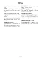
SECTION 2
TEST MODE
INITIALIZATION MODE
* All preset contents are cleared when this mode is activated. Use
this mode before returning the product to clients upon completion
of repair.
* Procedure:
While depr essing the VIDEO and the TAPE/MD buttons
simultaneously, press the power [I/
u
] button to turn on the main
power. The message INITIAL appears and initialization is
performed.
FLUORESCENT INDICATOR TUBE TEST MODE
* All fluorescent segments are tested. When this test is activated,
all segments turn on at the same time, then each segment turns on
one after another.
* Procedure:
While depressing the TV/LD and the BASS BOOST buttons
simultaneously, press the power [I/
u
] button to turn on the main
power. All segments turn on at the same time, then each segment
turns on one after another. The message FINISH appears when this
test is complete.
AUTO-BETICAL CHECK MODE
* To auto-scanning FM board and memorise RDS station. (FM/
RDS model only)
* Procedure:
While depressing the MEMORY button, press the power [I/
u
]
button to turn on the main power. The message AUTO BET appears
and each function is selected one after another.
AM CHANNEL STEP 9 kHz/10 kHz
SELECTION MODE
* Either the 9 kHz step or 10 kHz step can be selected for the AM
channel step. (US, CND and E model only)
* Procedure:
Set the FUNCTION to AM. Turn off the main power.
While depressing the button, press the power [I/
u
] button
to turn on the main power. Either the message 9k STEP or 10k
STEP appears. Select the desired step.
REAR SPEAKER GAIN UP MODE
* The rear speaker gain can be set to either NORMAL or GAIN UP.
* Procedure:
While depressing the -SURROUND- MODE button, press the power
[I/
u
] button to turn on the main power. Either the message
NORMAL or GAIN UP appears. When the product enters this
mode again, the other gain appears. Select the desired gain.
SOFTWARE VERSION DISPLAY MODE
* The software version is displayed.
* Procedure:
While depressing the TUNER and the BASS BOOST buttons
simultaneously, press the power [I/
u
] button to turn on the main
power. The software version is displayed.
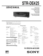
Summary of Contents for STR-DE425 - Fm Stereo/fm-am Receiver
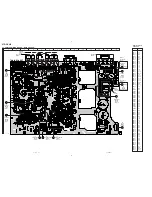
Page 8: ...STR DE425 9 10 3 3 SCHEMATIC DIAGRAM DISPLAY SECTION ...
Page 10: ...STR DE425 13 14 3 5 SCHEMATIC DIAGRAM POWER SECTION ...
Page 13: ...STR DE425 19 20 3 8 SCHEMATIC DIAGRAM MAIN SECTION 1 3 ...
Page 14: ...STR DE425 21 22 3 9 SCHEMATIC DIAGRAM MAIN SECTION 2 3 ...
Page 15: ...STR DE425 23 24 3 10 SCHEMATIC DIAGRAM MAIN SECTION 3 3 ...


