background image

6

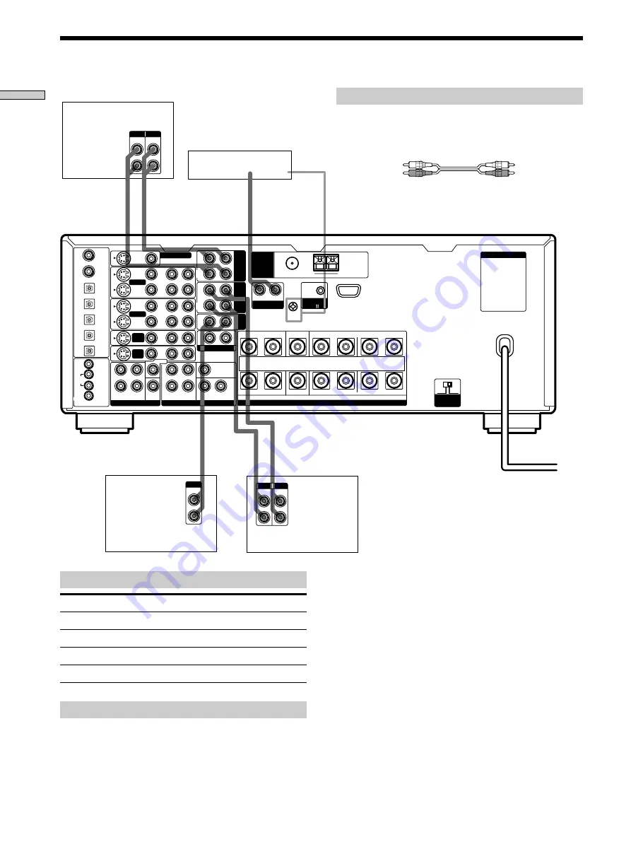
Hooking Up the Components

AC  OUTLET

IN

OUT

LINE

L

R

LINE

INPUT OUTPUT

ç

ç

IN

OUT

LINE

L

R

LINE

INPUT OUTPUT

ç

ç

LINE

L

R

OUTPUT

+

SPEAKERS

IMPEDANCE  USE  4 - 16

FRONT

REAR

CENTER

B

A

L

R

L

R

L

R

R

L

R

L

R

IN

REC
OUT

IN

IN

OUT

IN

IN

IN

OUT

IN

CENTER

SUB WOOFER

REAR

FRONT

CENTER

SUB

WOOFER

REAR

FRONT

TV/

SAT

DVD/

LD

VIDEO 1

MONITOR OUT

VIDEO 2

REC
OUT

L

R

AUDIO

S-VIDEO

DVD/LD
IN COAX

CD
IN COAX

DVD/LD
IN OPT

TV/SAT
IN OPT

MD/DAT
IN OPT

MD/DAT
OUT OPT

CD
IN OPT

MONITOR

CTRL S

IN

STATUS

IN

CTRL S

OUT

VIDEO 1

DVD/
LD

TV/
SAT

VIDEO

L

2ND AUDIO OUT

PRE OUT

5.1CH INPUT

4 Ω

IMPEDANCE

SELECTOR

CONTROL

A1    

TAPE

MD/

DAT

CD

L

SIGNAL GND

AM

y

y

F M     7 5

Ω 

C O A X I A L

ANTENNA

PHONO

R

White (L)

White (L)

Red (R)

Red (R)

Jacks for connecting audio components

Connect a

To the

Turntable

PHONO jacks

CD player

CD jacks

Tape deck

TAPE jacks

MD deck or DAT deck

MD/DAT jacks

Note on audio component hookups

If your turntable has a ground wire, connect it to the
SIGNAL GND 

y

 terminal on the receiver.

Required cords

Audio cords (not supplied)

When connecting a cord, be sure to match the color-coded pins to
the appropriate jacks on the components.

Audio Component Hookups

Turntable

(MM cartridge type only)

Tape deck

MD or DAT deck

CD player

Summary of Contents for STR-DA777ES - Fm Stereo/fm-am Receiver

Page 1: ...3 866 967 11 1 FM Stereo FM AM Receiver 1999 by Sony Corporation STR DA777ES Operating Instructions ...

Page 2: ...ver pull the cord One blade of the plug is wider than the other for the purpose of safety and will fit into the wall outlet only one way If you are unable to insert the plug fully into the outlet contact your dealer AC power cord must be changed only at the qualified service shop On placement Place the receiver in a location with adequate ventilation to prevent heat buildup and prolong the life of...

Page 3: ... No 5 451 942 and other worldwide patents issues and pending DTS and DTS Digital Surround are trademarks of Digital Theater Systems Inc 1996 Digital Theater Systems Inc All rights reserved TABLE OF CONTENTS Hooking Up the Components 4 Unpacking 4 Antenna Hookups 5 Audio Component Hookups 6 Video Component Hookups 7 Digital Component Hookups 8 5 1CH Input Hookups 10 Other Hookups 11 Hooking Up and ...

Page 4: ...eplace batteries Under normal conditions the batteries should last for about 3 months When the remote no longer operates the receiver replace all batteries with new ones Notes Do not leave the remote in an extremely hot or humid place Do not use a new battery with an old one Do not expose the remote sensor to direct sunlight or lighting apparatuses Doing so may cause a malfunction If you don t use...

Page 5: ... AM loop antenna supplied Important If you connect the receiver to an outdoor antenna ground it against lightning To prevent a gas explosion do not connect the ground wire to a gas pipe Note Do not use the SIGNAL GND y terminal for grounding the receiver Terminals for connecting the antennas Connect the To the AM loop antenna AM terminals FM wire antenna FM 75Ω COAXIAL terminal Notes on antenna ho...

Page 6: ...EO 1 DVD LD TV SAT VIDEO L 2ND AUDIO OUT PRE OUT 5 1CH INPUT 4 Ω 8 Ω IMPEDANCE SELECTOR CONTROL A1 TAPE MD DAT CD L SIGNAL GND AM y y FM 75Ω COAXIAL ANTENNA PHONO R White L White L Red R Red R Jacks for connecting audio components Connect a To the Turntable PHONO jacks CD player CD jacks Tape deck TAPE jacks MD deck or DAT deck MD DAT jacks Note on audio component hookups If your turntable has a g...

Page 7: ...nd 12 for details Yellow video Yellow video White L audio White L audio Red R audio Red R audio Yellow Yellow To the front panel Note on video component hookups You can connect your TV s audio output jacks to the TV SAT or TV LD AUDIO IN jacks on the receiver and apply sound effects to the audio from the TV In this case do not connect the TV s video output jack to the TV SAT or TV LD VIDEO IN jack...

Page 8: ...d pins to the appropriate jacks on the components DVD player etc Connect the digital output jacks of your DVD player and satellite tuner etc to the receiver s digital input jacks to bring the multi channel surround sound of a movie theater into your home To enjoy the full effect of multi channel surround sound five speakers two front speakers two rear speakers and a center speaker and a sub woofer...

Page 9: ...ed Audio cords not supplied When connecting a cord be sure to match the color coded pins to the appropriate jacks on the components White L White L Red R Red R Connect the digital output jack of your MD or DAT deck to the receiver s digital input jack and connect the digital input jack of your MD or DAT deck to the receiver s digital output jack These connections allow you to make digital recordin...

Page 10: ...ions described below adjust the level of your surround speakers and sub woofer from the DVD player or multichannel decoder 5 1CH Input Hookups Although this receiver incorporates a multi channel decoder it is also equipped with 5 1CH INPUT jacks These connections allow you to enjoy multichannel software encoded in formats other than Dolby Digital AC 3 and DTS If your DVD player is equipped with 5 ...

Page 11: ...EL DECODING OPEN CLOSE MASTER VOLUME 1 9 8 7 2 3 6 5 4 AUDIO SPLIT DIGITAL ANALOG 1 u ENTER EQ SUR LEVEL TUNER CUSTOM SET UP VIDEO S VIDEO L AUDIO R 2ND AUDIO OUT AUDIO IN SPEAKERS R L 2 CH ANALOG DIRECT EQ BANK 5 1 CH INPUT SOUND FIELD PRESET SOUND FIELD INPUT SELECTOR MODE White L White L Red R Red R AC power cord The configuration shape and number of AC outlets on the rear panel varies accordin...

Page 12: ...llowing connections also change the input mode of the receiver to TV whenever you operate your TV VCR 1 DVD player Receiver Other Hookups Audio video control S connecting cord Pull the video cord away from the supplied audio video control S cable for connection A Control S connecting cord Note Refer to the instructions supplied with your TV for details regarding the operations you can control from...

Page 13: ... Make sure that the total power consumption of the component s connected to the receiver s AC OUTLET s does not exceed the wattage stated on the rear panel Do not connect high wattage electrical home appliances such as electric irons fans or TVs to this outlet Note If the AC power cord is disconnected for about two weeks the receiver s entire memory will be cleaned and the demonstration will start...

Page 14: ...king Up and Setting Up the Speaker System This chapter describes how to hook up your speaker system to the receiver how to position each speaker and how to set up your speakers to enjoy multi channel surround sound Brief descriptions of buttons and controls used to set up the speaker system SET UP button Press to enter the setup mode when specifying speaker types and distances Cursor buttons Use t...

Page 15: ...T jacks For example if you want to connect just the front speakers to another amplifier connect that amplifier to the PRE OUT FRONT L and R jacks Notes on speaker system hookup Twist the stripped ends of the speaker cords about 2 3 inch 10 mm Be sure to match the speaker cord to the appropriate terminal on the components to and to If the cords are reversed the sound will be distorted and will lack...

Page 16: ... while outputting a test tone or a test tone is output from a speaker other than the one whose name is currently displayed on the receiver the speaker may be short circuited If this happens check the speaker connection again Speaker impedance To enjoy multi channel surround connect front center and rear speakers with a nominal impedance of 8 ohms or higher and set the speaker IMPEDANCE SELECTOR to...

Page 17: ...splay Are you sure YES and press ENTER The unit automatically turns off and then turns on again All of the followings are reset to the factory settings or cleared All menu adjustments speaker settings equalizer settings sound field parameters etc The equalizer settings in the equalizer bank PHONES SPEAKERS A OFF A B B MEMORY A F D FM AM TUNER PRESET 0 10 MULTI CHANNEL DECODING OPEN CLOSE MASTER VO...

Page 18: ...ps 3 and 4 until you have set all of the parameters that follow Note When the adjustable range is exceeded the display blinks Please keep settings within areas A B and C as described on the left p Front speaker size FRONT SP LARGE Initial setting LARGE If you connect large speakers that will effectively reproduce bass frequencies select LARGE Normally select LARGE If the sound is distorted or you ...

Page 19: ...n circuitry we recommend setting the sub woofer s cut off frequency as high as possible p Front speaker distance FRONT XX feet meter Initial setting 16 feet 5 0 meter Set the distance from your listening position to the front left or right speaker A on page 18 Front speaker distance can be set in 1 foot 0 1 meter steps from 3 to 40 feet 1 0 to 12 0 meters If both speakers are not placed an equal d...

Page 20: ...60 30 A B A B 60 90 20 A B 30 B C C A Multi Channel Surround Setup p Sub woofer phase polarity S W PHASE NORMAL Initial setting NORMAL Set the sub woofer phase polarity There is usually no problem when the sub woofer phase polarity is set to NORMAL However depending on the type of front speakers the position of the sub woofer and the cut off frequency of the sub woofer setting the phase polarity t...

Page 21: ...equency for the low cut filter of the front left and right speakers when the front speakers are set to SMALL The bass frequencies lower than the cut off frequency are divided by the bass redirection circuitry and output from the sub woofer or other LARGE speakers In order to prevent clipping frequencies below the cut off frequency are not output from the front speakers p Center speaker roll off fr...

Page 22: ...stment Although these adjustments can also be made via the front panel using the parameters in the LEVEL menu when the test tone is output the unit switches to the LEVEL menu automatically we recommend you follow the procedure described above and adjust the speaker levels from your listening position using the remote control z When setting the volume levels for each speaker Let s assume that you h...

Page 23: ...t component Check that the cord s used for the connection is are fully inserted into the jacks on both the receiver and the component No sound is heard from one of the front speakers Connect a pair of headphones to the PHONES jack and set the SPEAKERS selector to OFF to verify that sound is output from the headphones see SPEAKERS selector and PHONES jack on page 27 If only one channel is output fr...

Page 24: ...position to avoid damaging you speakers 2 INPUT SELECTOR control Turn to select the component you want to use To select Turn to light VCR VIDEO 1 VIDEO 2 or VIDEO 3 DVD player DVD LD or DVD LD player DVD LD or TV LD Satellite tuner or TV tuner TV SAT or TV LD Tape deck TAPE MD or DAT deck MD DAT CD player CD Tuner TUNER Turntable PHONO U S A Canada models only After selecting the component turn on...

Page 25: ...IGITAL ANALOG button for details 4 DIGITAL ANALOG button Press to select either digital or analog audio signals for your digital components DVD LD DVD TV SAT TV LD CD and MD DAT Each press switches the input of the currently selected component as follows Select To AUTO Give priority to digital signals when there are both digital and analog connections If there are no digital signals analog is sele...

Page 26: ... preset sound field MULTI CHANNEL DECODING indicator This indicator lights when the unit is decoding signals recorded in a multi channel format Use the following buttons to enjoy surround sound For details see Enjoying Surround Sound starting from page 28 A F D button Press to set the unit to automatically detect the type of signals being input and perform the proper decoding This mode presents th...

Page 27: ...rn to adjust the selected speaker level surround and equalizer parameters etc ª SET UP button Press to activate the setup mode then use the cursor buttons to select the parameters You can then make various settings using the jog dial º LEVEL button Press to activate the speaker level parameters page 35 You can adjust the various speaker level parameters front balance rear balance etc CUSTOM button...

Page 28: ...ovide sound effects commonly found in movie theaters The virtual sound modes contain compelling applications of the Sony Digital Cinema Sound digital signal processing technology They shift the sound away from the actual speaker locations to simulate the presence of several virtual speakers The music etc sound modes are designed for use with standard audio sources and TV broadcasts They add reverb...

Page 29: ...z You can identify Dolby Surround encoded software by looking at the packaging Use discs with the logo In order to enjoy Dolby Digital AC 3 playback you must use discs bearing this logo z When sound signals with a sampling frequency of 96 kHz are input The sound signals are output in stereo automatically and the sound field is turned off z You can enjoy surround sound while listening to headphones...

Page 30: ... of V SEMI M DIMENSION page 31 to create 5 sets of virtual speakers surrounding the listener from the sound of the front speakers without using actual rear speakers Reproduces the sound characteristics of the Sony Pictures Entertainment Kim Novak Theater cinema production studio using the 3D sound imaging of V SEMI M DIMENSION page 31 to create 5 sets of virtual speakers surrounding the listener f...

Page 31: ...ets of virtual speakers surrounding the listener at approximately a 30 angle of elevation Uses 3D sound imaging to create 3 sets of virtual rear speakers from 1 set of actual rear speakers Uses 3D sound imaging to create virtual rear speakers from the sound of the front speakers without using actual rear speakers This mode creates 5 sets of virtual speakers surrounding the listener at a 30 angle o...

Page 32: ... Reproduces the feeling of a large open air stadium Obtains maximum audio impact from video game software VIRTUAL ENHANCED A Virtual Enhanced Surround A VIRTUAL ENHANCED B Virtual Enhanced Surround B SMALL HALL LARGE HALL OPERA HOUSE JAZZ CLUB DISCO CLUB CHURCH LIVE HOUSE ARENA STADIUM GAME Automatically detects the type of audio signal being input Dolby Digital DTS Dolby Pro Logic or standard 2 c...

Page 33: ...hen the disc being played contains the LFE Low Frequency Effect channel When the sound of the LFE channel signal is actually being reproduced the bars underneath the letters lights up to indicate the level Since the LFE signal is not recorded in all parts of the input signal the bar indication will fluctuate and may turn off during playback 6 S WOOFER Lights when the sub woofer selection is set to...

Page 34: ...Channel Display All speakers present Rear speakers absent Center speaker absent Rear center speakers absent Source sound displays The letters L C R etc indicate the source sound The boxes around the letters vary to show how the receiver downmixes the source sound based on the speakers settings When using music sound modes like LARGE HALL or SMALL HALL the receiver adds reverberation based on the s...

Page 35: ...eters and customize the receiver to suit your listening environment your speaker your components and your personal preferences 1 Press SET UP EQ SUR LEVEL or CUSTOM to display the menu you desire See Menu Function Table starting on the next page for a chart showing the menus and their respective parameters 2 Press the cursor buttons or to select the desired parameter from the selected menu 3 Turn ...

Page 36: ...D 120 Hz DIST UNIT feet meter EQUALIZER EQ FRONT BASS 0 dB From 10 0 to 10 0 dB in 0 5 dB steps Pages 39 40 FRONT BASS 250 Hz From 99 Hz to 1 kHz FRONT MID 0 dB From 10 0 to 10 0 dB in 0 5 dB steps FRONT MID 1 0 kHz From 198 Hz to 10 kHz FRONT MID WIDE WIDE MIDDLE NARROW FRONT TREBL 0 dB From 10 0 to 10 0 dB in 0 5 dB steps FRONT TREBL 2 5 kHz From 1 0 to 10 kHz CENTER BASS 0 dB From 10 0 to 10 0 ...

Page 37: ... dB steps MID 1 0 kHz From 198 Hz to 10 kHz MID WIDE WIDE MIDDLE NARROW TRE 0 dB From 10 to 10 dB in 1 dB steps TRE 2 5 kHz From 1 0 to 10 kHz LEVEL LEVEL TEST TONE OFF OFF AUTO L C R RS LS SW Pages 42 43 FRONT L____ ____R L R 17 step in 1 dB steps REAR L____ ____R L R 17 step in 1 dB steps CENT LEVEL 0 dB From 10 0 to 20 0 dB OFF in 0 5 dB steps REAR LEVEL 0 dB From 10 0 to 20 0 dB OFF in 0 5 dB ...

Page 38: ...AND STD STD WIDE 2ND AUDIO SOURCE SOURCE TUNER CD MD DAT TAPE S FIELD LINK OFF OFF ON AUTO FUNCTION ON OFF ON 2 way REMOTE ON OFF ON XXXXXXXX select a character to input a name MEMORY CLEAR NO NO YES SLEEP OFF OFF 0 30 00 9 00 00 in 30 minute steps TUNER TUNER TUNER MODE AUTO AUTO MANUAL Page 49 51 FM MODE STEREO STEREO MONO FM A1 input a station name AM 10 kHz 9 kHz NO NO YES PRESET CLEAR NO NO Y...

Page 39: ...DDLE provides a normal band NARROW provides a narrow band centered on the selected frequency for specific adjustments Adjusting the Speaker Settings SP SETUP See Multi Channel Surround Setup on page 18 for details on the parameters available in the SET UP menu p Front speaker size FRONT SP Initial setting LARGE p Center speaker size CENTER SP Initial setting LARGE p Rear speaker size REAR SP Initi...

Page 40: ...ps The frequency can be adjusted from 1 0 kHz to 10 kHz in 23 steps p Rear speaker bass adjustment Level Frequency REAR BASS XX XdB REAR BASS XXXHz Adjust as described in Front speaker bass adjustment The level can be adjusted 10 dB in 0 5 dB steps The frequency can be adjusted from 99 Hz to 1 kHz in 21 steps p Rear speaker midrange adjustment Level Frequency REAR MID XX XdB REAR MID XXXHz Adjust ...

Page 41: ...1 0 kHz to 10 kHz in 23 steps Customizing Sound Fields SURROUND The SURROUND menu contains parameters that let you customize various aspects of the current sound field The settings available in this menu are stored individually for each sound field p Effect Level SURR EFFECT XXX Initial setting depends on sound mode This parameter lets you adjust the presence of the current digital cinema sound su...

Page 42: ...aker volume page 21 p Center level CENT LEVEL XX XdB Initial setting 0 dB Lets you adjust level of the center speaker The level can be adjusted in 1 dB steps from 20 dB to 10 dB This setting can also be adjusted directly using the supplied remote See Adjusting the speaker volume page 21 p Rear level REAR LEVEL XX XdB Initial setting 0 dB Lets you adjust level of the rear left and right speakers Th...

Page 43: ...other audio channels in the overall mix p Dynamic range compressor D RANGE COMP OFF Initial setting OFF Lets you compress the dynamic range of the sound track This may be useful when you want to watch movies at low volumes late at night OFF reproduces the sound track with no compression 0 1 0 9 allow you to compress the dynamic range in small steps to achieve the sound you desire STD reproduces th...

Page 44: ...A STUDIO EX A r r r r SEMI CINEMA STUDIO EX B r r r r SEMI CINEMA STUDIO EX C r r r r NIGHT THEATER r r r r MONO MOVIE r r r r STEREO MOVIE r r r r V MULTI DIMENSION r V MULTI REAR r V SEMI M DIMENSION r VIRTUAL ENHANCED A r VIRTUAL ENHANCED B r SMALL HALL r r r r LARGE HALL r r r r OPERA HOUSE r r r r JAZZ CLUB r r r r DISCO CLUB r r r r CHURCH r r r r LIVE HOUSE r r r r ARENA r r r r STADIUM r r...

Page 45: ...E r r r r r r r STEREO MOVIE r r r r r r r V MULTI DIMENSION r r r r r r r V MULTI REAR r r r r r r r V SEMI M DIMENSION r r r r r VIRTUAL ENHANCED A r r r r r VIRTUAL ENHANCED B r r r r r SMALL HALL3 r r r r r r r LARGE HALL3 r r r r r r r OPERA HOUSE3 r r r r r r r JAZZ CLUB3 r r r r r r r DISCO CLUB3 r r r r r r r CHURCH3 r r r r r r r LIVE HOUSE3 r r r r r r r ARENA3 r r r r r r r STADIUM3 r r...

Page 46: ...ignals to the sub room When SOURCE is selected the analog signals of the source selected as the function are output to the sub room Be sure to hook up the stereo amplifier in the sub room to this receiver using the 2ND AUDIO OUT jacks see page 11 However if 5 1 CH is selected as the function the analog signals of the previously selected source are output to the sub room The CUSTOMIZE menu allows y...

Page 47: ... several 2 way remote control system components together be sure to place them close together in order to enable proper remote operation p Naming Program sources XXXXXXXX Lets you register a name of up to 8 characters for the currently selected function Touch or to move the position and turn the jog dial to select a character When you are finished entering the name press ENTER When you want to cle...

Page 48: ...tuned in stations using Direct Tuning or Automatic Tuning you can preset them to the receiver see page 50 Then you can tune in any of the stations directly by entering its 2 character code using the supplied remote see page 50 Up to 30 FM or AM stations can be preset The receiver will also scan all the stations that you have preset see page 50 Direct Tuning Using the Remote You can enter a frequen...

Page 49: ...see page 51 Singapore Malaysia models 9 kHz Other models 9 kHz to change to 10 kHz see page 51 Automatic Manual Tuning For details on the buttons used in this section see Brief descriptions of buttons used to receive broadcasts on this page 1 Press FM AM to select the FM or AM band 2 Press TUNER The last received station is tuned in 3 Press the cursor buttons or to display TUNE MODE AUTO 4 Press T...

Page 50: ...u can store the station start again from Step 3 6 Repeat Steps 2 to 5 to preset another station To change a preset number to another station Do Steps 1 to 5 to preset the new station to the number Clearing preset stations 1 Press TUNER to activate the tuner menu 2 Press the cursor buttons or to display PRESET CLEAR NO 3 Turn the jog dial to display PRESET CLEAR YES and press ENTER Are you sure No ...

Page 51: ...ne in receivable stations automatically select AUTO When you want to tune in a station that has a signal too weak to be tuned in AUTO mode select MANUAL to change the frequency manually p FM mode FM MODE Initial setting STEREO Normally select STEREO If FM stereo reception is poor select MONO You will not be able to enjoy the stereo effect but the overall sound will be clearer p Naming preset stati...

Page 52: ... sound field SOUND FIELD PRESET buttons Press to select a preset sound field INPUT SELECTOR control Rotate to select the source Cursor buttons Use to select parameters after pressing the EQ button Jog dial Use to adjust parameters and select sound fields etc Viewing detailed information about the audio source You can view information about the audio source currently selected When a digital audio s...

Page 53: ...FF Clearing Stored Equalizer Settings 1 Press EQ BANK repeatedly to select the equalizer you want to clear EQ PRESET 1 5 2 Press EQ 3 Press the cursor buttons or to display PRESET x clear NO x is the number of the current equalizer preset 4 Turn the jog dial to display PRESET x clear YES and press ENTER Are you sure NO is displayed 5 Once again turn the jog dial to display YES and press ENTER PRES...

Page 54: ...repare the component for playing For example insert the laser disc you want to record into the LD player 3 Insert a blank video tape into the VCR VIDEO 1 or VIDEO 2 for recording 4 Start recording on the recording VCR then start playing the video tape or laser disc you want to record z You can record the sound from any audio source onto a video tape while copying from a video tape or laser disc Af...

Page 55: ...ting Instructions supplied with your component s The CONTROL A1 Control System was designed to simplify the operation of audio systems composed of separate Sony components CONTROL A1 connections provide a path for the transmission of control signals which enable automatic operation and control features usually associated with integrated systems Currently CONTROL A1 connections between a Sony CD pl...

Page 56: ...he names of the function buttons In this case refer to the Operating Instructions supplied with the receiver When recording do not play any components other than the recording source It will cause the automatic function selection to operate Synchronized recording This function lets you conduct synchronized recording between the selected source and recorder components 1 Set the function selector on...

Page 57: ...he receiver eliminate the short circuit problem and turn on the power again The left and right sounds are unbalanced or reversed Check that the speakers and components are connected correctly and securely Adjust front balance parameter in the LEVEL menu Severe hum or noise is heard Check that the speakers and components are connected securely Check that the connecting cords are away from a transfo...

Page 58: ...s automatically for safety reasons Remove the cause of the external force then press OPEN CLOSE again see page 27 Radio stations cannot be tuned in Check that the antennas are connected securely Adjust the antennas and connect an external antenna if necessary The signal strength of the stations is too weak when tuning in with automatic tuning Use direct tuning Make sure you set the tuning interval...

Page 59: ... DAT TAPE TV SAT or TV LD DVD LD or DVD VIDEO 1 2 and VIDEO 3 10 Hz 100 kHz 0 5 2 0 dB ANALOG DIRECT Signal to noise ratio DIGITAL 100 dB A 20 kHz LPF PHONO 86 dB A 5 mV LINE 100 dB A 20 kHz LPF ANALOG DIRECT Inputs Analog PHONO Sensitivity 4 mV Impedance 50 kilohms LINE TUNER CD MD DAT TAPE TV SAT or TV LD DVD LD or DVD VIDEO 1 2 and VIDEO 3 Sensitivity 200 mV Impedance 50 kilohms Inputs Digital ...

Page 60: ...ty 50 dB m at 1 000 kHz or 999 kHz S N 54 dB at 50 mV m Harmonic distortion 0 5 50 mV m 400 kHz Selectivity At 9 kHz 35 dB At 10 kHz 40 dB Video section Inputs Video 1 Vp p 75 ohms S video Y 1 Vp p 75 ohms C 0 286 Vp p 75 ohms Outputs Video 1 Vp p 75 ohms S video Y 1 Vp p 75 ohms C 0 286 Vp p 75 ohms General Power requirements U S A Canada models 120 V AC 60Hz Singapore Malaysia models 220 230 V A...

Page 61: ...ange and a subwoofer channel for deep bass is independently provided This format is also called 5 1 because the subwoofer channel is counted as 0 1 channel since it functions only when a deep bass effect is needed All six channels in this format are recorded separately to realize superior channel separation Furthermore since all the signals are processed digitally less signal degradation occurs Th...

Page 62: ...UDIO OUT A D D A Coaxial CD Optial MD DAT CD MD DAT OUT 5 1CH INPUT FRONT Lch Analog Digital DVD LD DVD TV SAT TV LD DVD LD DVD D A Front R ch D A D A Subwoofer ch CENTER ch D A D A Rear R ch REAR Lch MASTER VOLUME DIGITAL FILTER DIGITAL FILTER DIGITAL FILTER DECODER DIGITAL INTERFACE RECEIVER POST PROCESSING POST PROCESSING ATT ATT DIRECT CD 5 1CH INPUT DIRECT D A ANT ...

Page 63: ... Logic Surround 61 DTS 61 Dubbing See Recording E F G Editing See Recording Effect level 41 H I J K L M N O Hookups 5 1CH input 10 AC power cord 13 audio components 6 CONTROL A1 12 digital components 8 9 speakers 15 video components 7 P Q Parameter 36 38 44 45 R Recording on an audio tape or MD 54 on a video tape 54 S Selecting component 24 sound field 29 Sound field adjustable parameters 41 custo...

Page 64: ...64 Additional Information Sony Corporation Printed in Japan ...

Reviews: