background image

41

GB

G

e

tting Star

te

d

Function for conversion of video signals

This receiver is equipped with a function for converting video signals.
• Composite video signals can be output as HDMI video and component video signals.
• Component video signals can be output as HDMI video and video signals.

As the initial setting, video signals input from the connected component are output to the HDMI 
OUT or MONITOR OUT jacks as shown in the table below. 
We recommend you set the video conversion function to match the resolution of the monitor you 
are using.
For details on the video converting function, see “

Video settings” (page 123).

a

 : Video signals are output.

 : Video signals are not output.

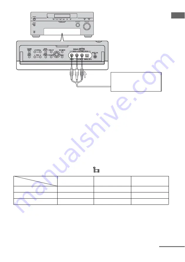
To the VIDEO 2 IN/

PORTABLE AV IN jacks

C

Audio/video cord (not supplied)

Camcorder, 
video game

Note

Before connecting cords, make sure to disconnect 
the AC power cord (mains lead).

C

HDMI OUT A B

COMPONENT VIDEO 

MONITOR OUT

MONITOR VIDEO OUT

HDMI IN 1/2/3/4/5/6

a

VIDEO IN

a

a

a

COMPONENT VIDEO IN

a

a

a

INPUT jack

OUTPUT jack

continued

Summary of Contents for STR DA6400ES

Page 1: ...Printed in Malaysia 2008 Sony Corporation STR DA6400ES 3 875 814 11 1 Operating Instructions Multi Channel AV Receiver ...

Page 2: ...mpanying the appliance For customers in the United States and Canada This symbol is intended to alert the user to the presence of the Hot Surface that may be hot if it is touched during the normal operation Owner s Record The model and serial numbers are located on the rear of the unit Record these numbers in the space provided below Refer to them whenever you call upon your Sony dealer regarding ...

Page 3: ...is no guarantee that interference will not occur in a particular installation If this equipment does cause harmful interference to radio or television reception which can be determined by turning the equipment off and on the user is encouraged to try to correct the interference by one or more of the following measures Reorient or relocate the receiving antenna Increase the separation between the e...

Page 4: ... Laboratories Manufactured under license under U S Patent s 5 451 942 5 956 674 5 974 380 5 978 762 6 226 616 6 487 535 other U S and worldwide patents issued pending DTS is a registered trademark and the DTS logos Symbol DTS HD and DTS HD Master Audio are trademarks of DTS Inc 1996 2007 DTS Inc All Rights Reserved This receiver incorporates High Definition Multimedia Interface HDMI technology HDM...

Page 5: ...mark and logos are owned by the Bluetooth SIG Inc and any use of such marks by Sony Corporation is under license Other trademarks and trade names are those of their respective owners BRAVIA is a trademark of Sony Corporation ...

Page 6: ...ite radio 70 Selecting a channel of the satellite radio 72 Presetting satellite radio channels 73 Restricting access to specific channels Parental Lock SIRIUS only 74 Enjoying Surround Sound Playing back with 2 channel sound 78 Playing back with multi channel surround 79 Enjoying a surround effect for music 82 Enjoying a surround effect for movies 84 Using Multi zone Features What you can do with ...

Page 7: ...41 Setting remote commander codes that are not stored in the remote 143 Clearing all the contents of the remote s memory 144 Using On screen Remote Quick Click Operating components or lighting connected to the receiver using the on screen remote Quick Click 145 Preparing Quick Click 146 Using Quick Click 147 Setting components that are operated by the on screen remote 153 Performing several comman...

Page 8: ...The receiver is turned off initial setting Press POWER to turn the receiver on You cannot turn the receiver on using the remote On Standby Press 1 on the remote to turn the receiver on or set it to the standby mode When you press POWER on the receiver the receiver will be turned off ...

Page 9: ... volume level of all speakers at the same time I INPUT SELECTOR Turn to select the input source to play back To select the input source for zone 2 or zone 3 press ZONE SELECT qh to select zone 2 or zone 3 first ZONE 2 INPUT or ZONE 3 INPUT appears on the display then turn INPUT SELECTOR to select the input source J 2CH A DIRECT Press to select sound field page 78 79 82 84 A F D MOVIE MUSIC K MULTI...

Page 10: ... for the Digital Cinema Auto Calibration function page 49 U VIDEO 2 IN PORTABLE AV IN jacks Connect to a portable audio videocomponent such as a camcorder or video game V MENU Press to display the menu of the receiver W RETURN Press to return to the previous menu or exit the current menu of the receiver X ZONE POWER Each time you press ZONE POWER the output signals for the selected zone will be tu...

Page 11: ...ubwoofer is connected and the audio signal is output from the SUBWOOFER jack While this indicator lights up the receiver creates a subwoofer signal based on the L F E signal in the disc being played back or the low frequency components of the front channels continued ...

Page 12: ...ent input INPUT Lights up constantly with either following the corresponding indicators that indicate the current input status HDMI The receiver recognizes a component connected via an HDMI IN jack DMPORT The DIGITAL MEDIA PORT adapter is connected and DMPORT is selected MULTI IN The multi channel input is selected NETWORK The input of the network function Server SHOUTcast Rhapsody is selected AUT...

Page 13: ...radio operation PRESET The tuning mode is set to the preset mode MEMORY A memory function such as Name Input etc is activated Name Function K H A T S Lights up when the H A T S High quality digital Audio Transmission System function is activated L BI AMP Lights up when surround back speakers selection is set to BI AMP M D RANGE Lights up when dynamic range compression is activated N VOLUME Display...

Page 14: ...ignals are input DTS Lights up when the receiver is decoding DTS signals Either 96 24 or NEO 6 also lights up depending on the input signal format or decoding format 96 24 DTS 96 24 96 kHz 24 bit decoding NEO 6 DTS Neo 6 Cinema Music DTS ES Lights up with the either following indicator depending on the input signal decoding format DISCRETE DTS ES Discrete 6 1 MATRIX DTS ES Matrix 6 1 Note When pla...

Page 15: ...r page 88 or an IR Blaster page 146 TRIGGER OUT jacks Connect to interlock on off of the power supply of other 12V TRIGGER compliant components or the amplifier receiver of zone 2 or zone 3 page 120 C DMPORT Connect to a Sony DIGITAL MEDIA PORT adapter page 29 D ANTENNA section FMANTENNA jack Connects to the FM wire antenna aerial supplied with this receiver page 43 AM ANTENNA jack Connects to the...

Page 16: ... or DVD player with an analog audio jack for 7 1 channel or 5 1 channel sound page 31 PRE OUT jacks Connect to an external power amplifier I VIDEO AUDIO INPUT OUTPUT section AUDIO IN OUT jacks Connect to a VCR or a DVD player etc page 26 38 39 40 VIDEO IN OUT jacks AUDIO OUT jacks VIDEO OUT jack Connect to the component in zone 2 or zone 3 page 88 ZONE 2 VIDEO OUT jack An RJ 45 jack used to send a...

Page 17: ... main receiver is turned on or off with this button To turn off all components including an amplifier in zone 2 or zone 3 press 1 and AV 1 1 at the same time SYSTEM STANDBY Saving the power in standby mode When Control for HDMI page 126 and RS 232C Control page 128 are set to OFF C ZONE Press to switch the zone 2 or zone 3 operation page 88 D AMP Press to enable the receiver operation page 45 E In...

Page 18: ...c Player etc R MENU HOME Press to display the menu used to operate audio video components or a TV Name Function S m M a x a X a N a b a Press to operate the DVD player Blu ray Disc Player CD player MD deck tape deck or component connected to the DIGITAL MEDIA PORT adapter etc CATEGORY MODE Press to select the category mode for satellite tuner TUNING Press to select station T PRESET b Press to regi...

Page 19: ...om the HDMI OUT or COMPONENT VIDEO MONITOR OUT jack ea PIP Press PIP to switch the image of the PIP Picture in Picture window The image of the PIP window is the one from the EXT VIDEO IN jack You can swap the position of the main screen and the PIP window by pressing qh Note When the HDMI input is selected on the main screen you cannot swap the position of the main screen and the PIP window es DIS...

Page 20: ... receivers in the main zone zone 2 and zone 3 and any other Sony components SYSTEM STANDBY C ZONE Press to enable the zone 2 or zone 3 operation page 88 D Input buttons Press one of the buttons to select the component you want to use Press a pink labeled button after pressing SHIFT qk When you press any of the input buttons the receiver turns on The buttons are factory assigned to control Sony com...

Page 21: ... then press TV CH to operate the TV satellite tuner VCR etc O RM SET UP Press to set up the remote P TV 1 Press to turn the TV on or off Q TV Press to enable the TV operation R SHIFT Press to light up the button It changes the remote button function to activate the buttons with pink printing S WIDE Press repeatedly to select the wide picture mode Name Function T TV INPUT Press TV qj then press TV ...

Page 22: ...CCenter speaker DSurround left speaker ESurround right speaker HSubwoofer You can enjoy high fidelity reproduction of DVD or Blu ray Disc software recorded sound in the Surround EX format if you connect one additional surround back speaker 6 1 channel system or two surround back speakers 7 1 channel system Example of a 7 1 channel speaker system configuration AFront left speaker BFront right speak...

Page 23: ...e angle A should be the same When you connect a 6 1 channel speaker system place the surround back speaker behind the seating position Since the subwoofer does not emit highly directional signals you can place it wherever you want ...

Page 24: ...FSurround back speaker R c GSurround speaker L HSurround speaker R a If you have an additional front speaker system connect them to the FRONT SPEAKERS B terminals You can select the front speaker system you want to use with the SPEAKERS switch OFF A B A B on the front panel page 48 H G F B A D E C A B FRONT SPEAKERS B terminals a AMonaural audio cord not supplied BSpeaker cords not supplied B B B ...

Page 25: ...Ω For details see 8 Setting the speakers page 46 Before connecting the AC power cord mains lead make sure that metallic wires of the speaker cords are not touching each other between the SPEAKERS terminals Tip To connect certain speakers to another power amplifier use the PRE OUT jacks The same signal is output from both the SPEAKERS terminals and the PRE OUT jacks For example if you want to conne...

Page 26: ...eiver using a GUI Graphical User Interface It is not necessary to connect all the cables Connect audio and video cords according to the jacks of your components TV monitor A B AOptical digital cord not supplied BAudio cord not supplied CVideo cord not supplied DComponent video cord not supplied EHDMI cable not supplied Audio signals C D E Video signals ...

Page 27: ... on the status of the connection between the TV and the antenna aerial the image on the TV screen may be distorted In this case place the antenna aerial farther away from the receiver Tips The receiver has a video conversion function For details see Notes on converting video signals page 42 The sound of the TV is output from the speakers connected to the receiver if you connect the audio output ja...

Page 28: ...nnect each component After hooking up all your components proceed to 5 Connecting the antennas aerials page 43 How to hook up your components Component to be connected Page Super Audio CD player CD player With digital audio output 29 With multi channel audio output 31 With analog audio output only 32 MD player With digital audio output 29 With analog audio output only 32 Tape deck Analog disc turn...

Page 29: ... adapter observe the following precautions Remove the DIGITAL MEDIA PORT adapter after removing the cord when cords are connected to the COMPONENT VIDEO jack Remove the DIGITAL MEDIA PORT adapter by squeezing the sides of the connector since the connector is locked in place Tip All the digital audio jacks are compatible with 32 kHz 44 1 kHz 48 kHz 88 2 kHz and 96 kHz sampling frequencies Connectin...

Page 30: ...D CD IN jacks Refer to the operating instructions supplied with the Super Audio CD player Connect a player which can output DSD signals from the HDMI jack to the receiver using an HDMI cable You cannot make digital recordings of a Super Audio CD When connecting optical digital cords insert the plugs straight in until they click into place If you want to connect several digital components but canno...

Page 31: ...ake sure to disconnect the AC power cord mains lead DVD player Blu ray Disc Player and Super Audio CD players may not have the SURROUND BACK jacks When Sur Back Assign is set to BI AMP or ZONE2 in the Speaker settings menu the input to the SUR BACK jacks is invalid Audio input signals from MULTI CHANNEL INPUT jacks are not output to any audio output jacks The signals cannot be recorded Connecting ...

Page 32: ...e deck and turntable etc Notes If your turntable has a ground earth wire connect it to the U SIGNAL GND terminal Before connecting cords make sure to disconnect the AC power cord mains lead Connecting components with analog audio jacks Super Audio CD player CD player Turntable A Tape deck AAudio cord not supplied A A MD deck A ...

Page 33: ...oceed to 5 Connecting the antennas aerials page 43 The image quality depends on the connecting jack Refer to the illustration that follows Select the connection according to the jacks on your components How to hook up your components Component to be connected Page TV monitor 26 With HDMI jack 34 DVD player Blu ray Disc Player 38 Satellite tuner Set top box 39 DVD recorder VCR 40 Camcorder video ga...

Page 34: ...I signals Audio signals are not output from an HDMI OUT jack when the image is converted This receiver supports DSD transmission Super Audio CD extended by HDMI ver1 2 This receiver supports High Bitrate Audio DTS HD Master Audio Dolby TrueHD Deep Color and xvYCC transmission extended by HDMI ver1 3 The HDMI jacks of this receiver support the Control for HDMI function The HDMI OUT B jack however d...

Page 35: ...o signals Audio video signals Audio video signals TV monitor projector etc Audio signals A A A Audio video signals To TV OPTICAL IN jacks C B Projector etc Audio video signals A AHDMI cable not supplied We recommend that you use a Sony HDMI cable BOptical digital cord not supplied CAudio cord not supplied continued ...

Page 36: ...e receiver Connect the OPTICAL output jack of the TV to the OPTICAL IN jack of the receiver Tips Connect to at least one of the audio cords B or C You can watch the image of the camcorder easily with connecting your camcorder to the HDMI IN 6 jack page 100 A Camcorder Audio video signals AHDMI cable not supplied We recommend that you use a Sony HDMI cable ...

Page 37: ...from the TV speaker Be sure to turn on the receiver when video and audio signals of a playback component are being output to a TV through this receiver Unless the power is on neither video nor audio signals will be transmitted Audio signals sampling frequency bit length etc transmitted from an HDMI jack may be suppressed by the connected component Check the setup of the connected component if an i...

Page 38: ...annel digital audio set the digital audio output setting on the DVD player Blu ray Disc Player Refer to the operating instructions supplied with the DVD player Blu ray Disc Player Before connecting cords make sure to disconnect the AC power cord mains lead Connecting a DVD player Blu ray Disc Player DVD player Blu ray Disc Player A B C AOptical digital cord not supplied BCoaxial digital cord not s...

Page 39: ...d video cords according to the jacks of your components Note Before connecting cords make sure to disconnect the AC power cord mains lead Connecting a satellite tuner Set top box Satellite tuner Set top box A B C D AOptical digital cord not supplied BAudio cord not supplied CVideo cord not supplied DComponent video cord not supplied Audio signals Video signals ...

Page 40: ...a DVD recorder or VCR etc It is not necessary to connect all the cables Connect audio and video cords according to the jacks of your components Connecting components with analog video and audio jack DVD recorder VCR A B Audio signals Video signals AAudio cord not supplied BVideo cord not supplied ...

Page 41: ...T jacks as shown in the table below We recommend you set the video conversion function to match the resolution of the monitor you are using For details on the video converting function see Video settings page 123 a Video signals are output Video signals are not output To the VIDEO 2 IN PORTABLE AV IN jacks CAudio video cord not supplied Camcorder video game Note Before connecting cords make sure t...

Page 42: ...hnology is converted Resolution of up to 480p can be output to the COMPONENT VIDEO MONITOR OUT jacks The HDMI OUT jack has no restriction on resolution Video signals for which the resolution has been converted cannot be output from either the COMPONENT VIDEO MONITOR OUT jacks or the HDMI OUT jack The video signals are output from the HDMI OUT jack when both are connected Set Resolution to AUTO or ...

Page 43: ...rea Notes To prevent noise pickup keep the AM loop antenna aerial away from the receiver and other components Be sure to fully extend the FM wire antenna aerial After connecting the FM wire antenna aerial keep it as horizontal as possible Before connecting cords make sure to disconnect the AC power cord mains lead FM wire antenna aerial supplied AM loop antenna aerial supplied ...

Page 44: ...onsumption of the component s connected to the receiver s AC OUTLET s does not exceed the wattage stated on the rear panel Do not connect high wattage electrical home appliances such as electric irons fans or TVs to this outlet This may cause a malfunction Before using the receiver for the first time initialize the receiver by performing the following procedure This procedure can also be used to r...

Page 45: ...batteries the programmed remote codes may be cleared If this happens program the remote codes again page 137 Tip When the remote no longer operates the receiver replace all the batteries with new ones 7 Displaying the GUI menu on the TV screen You can select the functions or change the settings of the receiver by using the GUI menu on the TV screen Follow the procedure below to make the settings s...

Page 46: ...for messages on the GUI menu on the TV screen from English Spanish French and German For details see System settings page 128 To exit the menu Press MENU 8 Setting the speakers Set the appropriate speaker impedance for the speakers you are using 1 Press AMP The receiver can be operated using the remote 2 Press MENU The menu is displayed on the TV screen Setting the speaker impedances AMP V v b MEN...

Page 47: ... speakers refer to the operating instructions supplied with your speakers This information is often on the back of the speaker When you connect all speakers with a normal impedance of 8 ohms or higher set Impedance to 8 Ω When connecting other types of speakers set it to 4 Ω When you connect front speakers to both the SPEAKERS A and B terminals connect the speakers with a normal impedance of 8 ohm...

Page 48: ... volume of the sound cannot be adjusted Pay attention to the presence of children or to the effect on your neighborhood Perform the measurement in a quiet environment to avoid the effect of noise and get a more accurate measurement If there are any obstacles in the path between the optimizer microphone and the speakers the calibration cannot be performed correctly Remove any obstacle from the meas...

Page 49: ...n auto standby function set it to off deactivated Note Depending on the characteristics of the subwoofer you are using the setup distance value may be further away from the actual position To use the receiver as a pre amplifier You can use the auto calibration function when you use the receiver as a pre amplifier In this case the distance value shown on the display may differ from the actual dista...

Page 50: ... kHz are being received 1 Press AMP The receiver can be operated using the remote 2 Press MENU The menu is displayed on the TV screen 3 Press V v repeatedly to select Settings then press or b The Settings menu list appears on the TV screen 4 Press V v repeatedly to select Auto Calibration then press or b 5 Press V v repeatedly to select Quick Setup then press The screen on which you can select the...

Page 51: ... displayed on the TV screen The and terminals of the speaker may be connected the other way around However depending on the speakers Out Phase appears on the TV screen even though the speakers are connected properly This is because of the speakers specifications In this case you can continue to use the receiver Tips Operations other than turning the receiver on or off are deactivated during the me...

Page 52: ...ct is being used The measurement result is not utilized when Dolby TrueHD signals with a sampling frequency of higher than 96 kHz are being received Tip The size of a speaker LARGE SMALL is determined by the low characteristics The measurement results may vary depending on the position of the optimizer microphone and speakers and the shape of the room It is recommended that you follow the measurem...

Page 53: ...y be damaged or improperly connected Code 33 None of the front speakers are connected or only one front speaker is connected The optimizer microphone is not connected Either the left or right surround speakers is not connected Surround back speakers are connected even though surround speakers are not connected Connect the surround speaker s to the SURROUND terminals The surround back speaker is co...

Page 54: ... continue to use the receiver with that value Warning 44 Measurement has been completed However the speakers are not placed in the proper position with respect to each other See 1 Installing speakers page 22 and check the relative positions of the speakers NO WARNING There is no warning information No speakers are connected Display Explanation ...

Page 55: ... 1 Press AMP The receiver can be operated using the remote 2 Press MENU The menu is displayed on the TV screen 3 Press V v repeatedly to select the menu you want then press or b to enter the menu mode The menu item list appears on the TV screen Example When you select Input 4 Press V v repeatedly to select the menu item you want to adjust then press to enter the menu item 5 Repeat steps 3 and 4 to...

Page 56: ...lects the input source component connected to the receiver page 58 Music Selects the music from the audio component connected to the DIGITAL MEDIA PORT adapter page 60 or server on the home network Photo Select the photos from the server on the home network Video Select the images from the video component connected to the DIGITAL MEDIA PORT adapter page 60 or server on the home network Rhapsody Se...

Page 57: ...57GB Getting Started 5 Press V v repeatedly to select the option menu item you want then press 6 Press V v repeatedly to select the parameter you want then press To exit the menu Press MENU ...

Page 58: ...ese operating instructions for details on playing back content on your home network MASTER VOL MUTING AMP OPTIONS MENU V v B b Selected input Components that can be used Video1 Video2 VIDEO 1 2 VCR etc connected to the VIDEO 1 or VIDEO 2 jack BD Blu ray Disc Player etc connected to the BD jack DVD DVD player etc connected to the DVD jack SAT Satellite tuner etc connected to the SAT jack TV TV conn...

Page 59: ...connected components 1 Press V v repeatedly on the Input screen to select the input you want to name 2 Press OPTIONS The option menu appears 3 Press V v repeatedly to select Name Input then press The soft keyboard appears on the screen 4 Press V v B b and to select a character one by one to enter the name 5 Press V v B b to select Finish then press The name you entered is registered To cancel nami...

Page 60: ...T Adapter TDM iP1 iP10 iP50 DIGITAL MEDIA PORT Adapter TPM MP10 DIGITAL MEDIA PORT Adapter The DIGITAL MEDIA PORT adapter is an optional product Notes Do not connect an adapter other than the DIGITAL MEDIA PORT adapter Before disconnecting the DIGITAL MEDIA PORT adapter make sure to turn the receiver off using the remote Do not connect or disconnect the DIGITAL MEDIA PORT adapter to from the recei...

Page 61: ...will change to the respective component s name with an icon If the adapter connected cannot be recognized DMPORT1 or DMPORT2 is displayed on the TV screen 5 Select a track you want to play using the component connected to the DIGITAL MEDIA PORT adapter 6 Press MASTER VOL to adjust the volume MASTER VOL AMP MENU V v b Icon Component that is connected DMPORT A component other than one of the followi...

Page 62: ... select track or content from the contents list The following content lists are just examples They may vary depending on the components connected to the receiver In case of iPod 6 Press MASTER VOL to adjust the volume 1 Play back the track you want to listen to following the steps outlined in Operating the TDM iP1 iP50 using the GUI menu of the receiver page 62 2 Press OPTIONS The option menu appe...

Page 63: ...ORT Control mode is supported by the DIGITAL MEDIA PORT adapters like TDM iP1 iP50 This mode is not supported by other adapters 1 Press V v repeatedly on the Music or Video screen to select the DIGITAL MEDIA PORT adapter you want then press or b 2 Press OPTIONS The option menu appears 3 Press V v to select DMPORT Control then press If DMPORT Control is not displayed see the operating instructions ...

Page 64: ... in step 4 in Changing the operation screen using the DIGITAL MEDIA PORT page 63 For details on operating the adapter using the adapter GUI menu refer to the operating instructions supplied with the adapter you are using To operate the TDM iP1 iP50 using the iPod menu Make sure that iPod is selected in step 4 in Changing the operation screen using the DIGITAL MEDIA PORT page 63 For details on oper...

Page 65: ... list appears on the TV screen 4 Press V v to select Auto Tuning then press 5 Press V v Press V to scan from low to high press v to scan from high to low The receiver stops scanning whenever a station is received In case of poor FM stereo reception 1 Tune in the station you want to listen to using Auto Tuning Direct Tuning page 66 or select the preset station you want page 67 2 Press OPTIONS The o...

Page 66: ...enna aerial for optimum reception If you cannot tune in a station MHz appears and then the display returns to the current frequency Make sure you have entered the right frequency If not repeat step 5 If you still cannot tune in a station the frequency is not used in your area You can change the AM tuning scale to either 9 kHz or 10 kHz on the receiver 1 Press POWER to turn off the receiver 2 While...

Page 67: ... 4 to preset another station You can store stations as follows AM band AM1 to AM30 FM band FM1 to FM30 1 Press AMP The receiver can be operated using the remote 2 Press MENU The menu is displayed on the TV screen 3 Press V v repeatedly to select FM or AM then press or b 4 Press V v to select the preset number station you want Preset numbers from 1 to 30 are available 1 On FM or AM screen press V v...

Page 68: ...ner Care at 1 800 XMRADIO 1 800 967 2346 Canadian customers visit xmradio ca or call XM Listener Care at 1 877 GETXMSR 1 877 438 9677 XM Ready Legal XM monthly service subscription sold separately XM Mini Tuner and Home Dock required each sold separately to receive XM service It is prohibited to copy decompile disassemble reverse engineer hack manipulate or otherwise make available any technology ...

Page 69: ...p to an hour When you can access the full lineup on your XM Ready audio system you are done SIRIUS Satellite Radio The Best Radio On Radio SIRIUS brings all your favorite entertainment including 100 commercial free music plus superior sports coverage uncensored talk and comedy world class entertainment news weather and more for your car home or office Sirius is available in the US for subscribers ...

Page 70: ...nect to the SIRIUS jack Connect the SiriusConnect Home tuner When you use the SiriusConnect Home tuner with this receiver be sure to connect the AC power adaptor supplied with the tuner to a wall outlet Keep the SiriusConnect Home tuner antenna and AC power adaptor away from the speaker cords and the power cord to avoid picking up noise Preparing to listen to a satellite radio 1 Press AMP The rece...

Page 71: ...D _________________________ You can also check the XM Radio ID and Sirius ID using the display on the receiver 1 Press AMP The receiver can be operated using the remote 2 Press MENU The menu is displayed on the TV screen 3 Press V v repeatedly to select XM or SIRIUS then press or b 4 Press OPTIONS The option menu appears 5 Press V v repeatedly to select Antenna Aiming then press The Antenna Aiming...

Page 72: ...ry Mode 6 Press V v to select the channel then press The selected channel is being received The channel information is displayed on the TV screen Note When you select a channel in the Category Mode the channel you selected may not be the one in the category you want This is because one channel may belong to more than one category 1 Press AMP The receiver can be operated using the remote 2 Press ME...

Page 73: ... using the preset numbers You can preset up to 30 XM Radio channels and 30 SIRIUS Satellite Radio channels 1 Select a channel you want to preset using Category Mode page 72 or Direct Tuning page 72 2 Press OPTIONS The option menu appears 3 Press V v to select Memory then press The preset number selection screen appears AMP V v b OPTIONS MENU continued ...

Page 74: ...ress You can select stored preset channels from 1 to 30 Notes The channel information you have preset may be changed if XM Satellite Radio Inc or SIRIUS Satellite Radio Inc change their channel programming When the Category Mode screen is displayed press OPTIONS then press V v to select Preset Mode Restricting access to specific channels Parental Lock SIRIUS only You can restrict access to certain...

Page 75: ... the locked channels 1 Select a locked channel you want to listen to using Category Mode page 72 or Direct Tuning page 72 The channel is locked Enter your 4 digit lock code appears 2 Enter your 4 digit lock code using the numeric buttons The channel is tuned in To cancel the Parental Lock 1 Select a channel you want to unlock using Category Mode page 72 or Direct Tuning page 72 2 Press OPTIONS The...

Page 76: ...alid Channel You have entered an invalid channel number The channel to be tuned in is void due to the change by the broadcast service or the receiving condition is not good Locked Channel The selected channel is locked Subscription Updated The subscription information has been updated Updating Channels xx Completed xx are for integers Channel information is being updated Firmware Updating The Siri...

Page 77: ...seconds in good signal conditions If you see this message often reposition the XM antenna for better signal reception Use the Antenna Aiming option to optimize the antenna position page 71 Off Air You selected an XM channel is not currently broadcasting Check back later in the mean time select another channel space No artist name or song title is available for this selection No action required CH ...

Page 78: ... you select A F D Auto the receiver will generate a low frequency signal for output to the subwoofer from a 2 channel signal even if there is no L F E signal Enjoying Surround Sound 2CH mode Effect 2ch Stereo The receiver outputs the sound from the front left right speakers only There is no sound from the subwoofer Standard 2 channel stereo sources completely bypass the sound field processing and ...

Page 79: ...A F D mode you want A F D mode Multi channel audio after decoding Effect A F D Auto Detecting automatically Presets the sound as it was recorded encoded without adding any surround effects Multi Stereo Multi Stereo Outputs 2 channel left right signals from all speakers Enhanced Surround You can select the surround sound effect you want For details on available surround sound effects and how to set...

Page 80: ...channel format is decoded into 5 1 channels This setting is ideal for movies encoded in Dolby Surround In addition this mode can reproduce sound in 5 1 channel system for watching videos of overdubbed or old movies PLIIx 7 channel signals Performs Dolby Pro Logic IIx mode decoding A source recorded in 2 channel or 5 1 channel format is decoded into 7 1 channels This setting is ideal for movies enc...

Page 81: ...with a sampling frequency of higher than 48 kHz the signals will always be played back at either 44 1 kHz or 48 kHz If you set up the sound field during DTS 96 24 signal reception the signal will be played back only at 48 kHz The beginning of the sound stream may be dropped out when Neural THX processing is turned on or off Tips We usually recommend A F D Auto You can identify the encoding format ...

Page 82: ... a concert hall which simulates a large sound stage produced by reflectivity D Concert Hall B Uses 3D sound imaging to reproduce the sound characteristics of a concert hall which simulates resonant and unique reverberative sound Jazz Club Reproduces the acoustics of a jazz club Live Concert Reproduces the acoustics of a 300 seat live house Stadium Reproduces the feeling of a large open air stadium...

Page 83: ...the subwoofer if all the speakers are set to LARGE in the Speaker settings menu However the sound will be output from the subwoofer if the digital input signal contains L F E signals or if the front or surround speakers are set to SMALL the sound field for movie is selected or Portable Audio is selected Sound field Effect Headphone 2ch This mode is selected automatically if you use headphones when...

Page 84: ... Entertainment Cary Grant Theater cinema production studio This is a standard mode great for watching almost any type of movie Cinema Studio EX B D CS Reproduces the sound characteristics of the Sony Pictures Entertainment Kim Novak Theater cinema production studio This mode is ideal for watching science fiction or action movies with lots of sound effects Cinema Studio EX C D CS Reproduces the sou...

Page 85: ...ignal will be played back only at 48 kHz If you set up the sound field effect while the receiver is receiving signals with a sampling frequency of higher than 48 kHz the signals will always be played back at either 44 1 kHz or 48 kHz The effects provided by the virtual speakers may cause increased noise in the playback signal When listening with sound fields that employ the virtual speakers you wi...

Page 86: ...l audio formats supported by the receiver Audio format Maximumnumber of channels Connection of the playback component and the receiver COAXIAL OPTICAL HDMI Dolby Digital 5 1ch a a Dolby Digital EX 6 1ch a a Dolby Digital Plus a 7 1ch a Dolby TrueHD a 7 1ch a DTS 5 1ch a a DTS ES 6 1ch a a DTS 96 24 5 1ch a a DTS HD High Resolution Audio a 7 1ch a DTS HD Master Audio a b 7 1ch a ...

Page 87: ...t For details refer to the operating instructions of the playback component b Signals with a sampling frequency of higher than 96 kHz are played back at 96 kHz or 88 2 kHz DSD a 5 1ch a Multi channel Linear PCM a 7 1ch a Audio format Maximumnumber of channels Connection of the playback component and the receiver COAXIAL OPTICAL HDMI ...

Page 88: ...ing an IR repeater not supplied you can operate both a component in the main zone and Sony receiver in zone 2 or zone 3 from zone 2 or zone 3 To operate the receiver from zone 2 or zone 3 You can operate the receiver without pointing the remote toward the IR repeater of the receiver if you connect an IR repeater not supplied to the IR REMOTE jack Use an IR repeater when you install the receiver in...

Page 89: ...2 using the receiver and another amplifier AIR repeater not supplied BSpeakers CSony Amplifier Receiver You can also connect to the COMPONENT VIDEO ZONE 2 OUT jack 1 Zone 2 connections Main zone Zone 2 TV monitor ZONE 2 VIDEO OUT B STR DA6400ES B SURROUND BACK SPEAKERS A RM AAP026 IR REMOTE IN Main zone Zone 2 TV monitor ZONE 2 AUDIO OUT A B B C STR DA6400ES RM AAP026 IR REMOTE IN ZONE 2 VIDEO OUT...

Page 90: ...90GB 2 Zone 3 connections B B C STR DA6400ES Main room Zone 3 AIR repeater not supplied BSpeakers CSony Amplifier Receiver RM AAP026 A IR REMOTE IN ZONE 3 AUDIO OUT ...

Page 91: ...ration below Note CAV CVB1 Component Video Balun must be used Other types will cause trouble and may void your warranty RJ45 Video Pinout The RJ45 pinouts use the T568B standard Refer to the illustration below Making a zone 2 configuration using ZONE 2 VIDEO OUT RJ45 jack Component Video Balun CAV CVB1 ZONE 2 VIDEO OUT RJ45 jack CAT5 cable Component video cable TV monitor Zone 2 Pinout Wire color ...

Page 92: ...t Use Category 5e or Category 6 cable CAT5 cable RJ45 connector RJ45 connector White Orange Wire color Orange White Green Blue White Blue Green White Brown Brown 1 Pin No 2 3 4 5 6 7 8 White Orange Orange White Green Blue White Blue Green White Brown Brown 1 2 3 4 5 6 7 8 ...

Page 93: ...s 1 Press AMP The receiver can be operated using the remote 2 Press MENU The menu is displayed on the TV screen 3 Press V v repeatedly to select Settings then press or b 4 Press V v repeatedly to select Speaker then press or b 5 Press V v to select Speaker Pattern to select the pattern that has no surround back speakers 6 Press RETURN EXIT O 7 Press V v repeatedly to select Sur Back Assign then pr...

Page 94: ...utton 2 for the zone 2 or 3 for the zone 3 while the ZONE button is flashing The ZONE button lights up 4 Press ENT MEM The ZONE button flashes twice and the remote switches to zone 2 or zone 3 mode On the zone 2 zone 3 remote commander 1 Press 1 while pressing RM SET UP The RM SET UP button flashes and the SHIFT button lights up 2 Press the numeric button 2 for the zone 2 or 3 for the zone 3 while...

Page 95: ...n is activated 5 Press MENU The menu is displayed on the TV screen 6 Press V v to select Input then press or b 7 Press V v to select the input source you want then press For zone 2 analog video and audio signals are output When you select SOURCE the signals of the current input of the main zone are output to the ZONE 2 OUT jack 8 Adjust to a suitable volume In the case of illustration 1 1 page 89 ...

Page 96: ...ver the receiver in zone 2 or zone 3 remains turned on To turn off all receivers press 1 and AV 1 on the main remote at the same time SYSTEM STANDBY Only signals from components connected to the analog input jacks are output through the ZONE 2 or ZONE 3 jacks No signals are output from components connected to only the digital input jacks When SOURCE is selected the signals input to the MULTI CHANN...

Page 97: ...nd of the input selected in main zone is output in the zone selected in party mode page 121 To exit the party mode Select other input in zone 2 or zone 3 Refer to Operating the receiver from another zone ZONE 2 ZONE 3 operations page 95 for details of the operation of zone2 zone 3 ...

Page 98: ...connect the receiver to products featuring BRAVIA Sync Note Depending on the connected component the Control for HDMI function may not work See the operating instructions of the component To use the BRAVIA Sync turn the Control for HDMI function on for both the receiver and the connected component The receiver is compatible with the Control for HDMI Easy Setting function When your TV is compatible...

Page 99: ...k components beforehand When you set up the receiver using the Control for HDMI Easy Setting from a TV before you make the Control for HDMI Easy Setting function effective make the Control for HDMI function of the components that are not compatible with the Control for HDMI Easy Setting function effective When your TV is not compatible with the Control for HDMI Easy Setting function Turn the Contr...

Page 100: ...r and TV Note Connect your camcorder to the HDMI IN 6 jack The camcorder may not work correctly if you connect it to the HDMI IN jack on the rear panel Depending on the TV the start of the content may not be output You can enjoy the TV sound from the speakers connected to the receiver by a simple operation Depending on the TV settings while you are watching the TV the receiver turns on and switche...

Page 101: ...he TV Depending on the status the connected components may not be turned off For details see the operating instructions of the connected components Switching the monitors that output the HDMI video signals When you have two monitors connected to the HDMI OUT A and HDMI OUT B jacks you can switch the output for these two monitors using the HDMI OUTPUT button 1 Turn on the receiver and the two monit...

Page 102: ... audio signals when there are both digital and analog connections If there are no digital audio signals analog audio signals are selected Analog Specifies the analog audio signals input to the AUDIO IN L R jacks Notes Some audio input modes may not be set up depending on the input When either HDMI input satellite tuner or DIGITAL MEDIA PORT adapter is selected appears on the display and you cannot...

Page 103: ...IDEO IN 3 jack of this receiver when you want to input the video signals from the DVD player Assign video and or audio signals to the DVD input jack using Input Assign in the Input menu 1 Press AMP The receiver can be operated using the remote 2 Press MENU The menu is displayed on the TV screen 3 Press V v repeatedly to select Input then press or b 4 Press V v to select the input name you want to ...

Page 104: ... same input You cannot reassign more than one digital audio input to the same input You cannot reassign more than one component video input to the same input When you assign a component video input to the HDMI input set Control for HDMI to OFF Input name VIDEO1 VIDEO2 BD DVD SAT TAPE MD SA CD CD MULTI IN HDMI1 HDMI2 HDMI3 HDMI4 HDMI5 HDMI6 Assignable video input jacks Video1 Composite aa Video2 Co...

Page 105: ... repeatedly Each time you press SLEEP the display changes cyclically as follows When sleep timer is being used SLEEP lights up in the display window of the receiver Tip To check the remaining time before the receiver turns off press SLEEP The remaining time appears on the display If you press SLEEP again the sleep timer will be changed SLEEP AMP ...

Page 106: ...V v repeatedly to select Audio then press or b 5 Press V v repeatedly to select Night Mode then press 6 Press V v repeatedly to select On then press Notes This function does not work when the multi channel input is selected This function does not work when Dolby TrueHD signals with a sampling frequency of higher than 96 kHz are being received If the Night Mode function is turned on while the recei...

Page 107: ...dio input signals from the MULTI CHANNEL INPUT jacks are not output To record digital sound Connect a component for playback to the digital audio input OPTICAL IN jack and connect the recording component to the OPTICAL MD OUT jack 1 Press the input button of the playback component 2 Prepare the component for playing For example insert the video tape you want to copy into the VCR 3 Prepare the reco...

Page 108: ...ou are operating the receiver using the remote supplied with the receiver The command modes of both the receiver and the remote are those of the initial setting COMMAND MODE AV 2 The receiver and the remote on the contrary should use the same command mode If the command modes of the receiver and the remote are different you cannot use the remote to operate the receiver Turn on the receiver while p...

Page 109: ...kers you can use the SURROUND BACK SPEAKERS terminals for the front speakers for use with a bi amplifier connection To connect speakers Connect the jacks on the Lo or Hi side of the front speakers to the FRONT SPEAKERS A terminals and connect the jacks on the Hi or Lo side of the front speakers to the SURROUND BACK SPEAKERS terminals Make sure that metal fittings of Hi Lo attached to the speakers ...

Page 110: ...om the SURROUND BACK SPEAKERS terminals Notes You cannot use the FRONT SPEAKERS B terminals for a bi amplifier connection When you use the auto calibration function make the bi amplifier settings before you perform auto calibration If you make the bi amplifier settings the speaker level balance and equalizer settings of the surround back speakers become invalid and those of the front speakers are ...

Page 111: ...creen page 45 1 Press AMP The receiver can be operated using the remote 2 Press MENU The menu is displayed on the TV screen 3 Press V v repeatedly to select Settings then press or b to enter the menu mode The setting menu list appears on the TV screen 4 Press V v repeatedly to select the menu item you want then press to enter Example When you select Auto Calibration 5 Press V v repeatedly to selec...

Page 112: ...nt to register the measurement results Pos Position 1 Pos Position 2 Pos Position 3 2 Press b to perform auto calibration To set a compensation type for the speakers You can select the compensation type to be used for the speakers for each Seating Position Menu icon Description Auto Calibration Sets the speaker level or distance and makes the measurement automatically page 112 Speaker Sets the spe...

Page 113: ...measurement results have not been registered To confirm the equalizer setting for the Seating Position 1 Press V v repeatedly to select the Seating Position for which you want to confirm the equalizer setting 2 Press OPTIONS The option menu appears 3 Press V v repeatedly to select EQ Curve then press 4 Press B b repeatedly to select the speaker on the screen for which you want to confirm the equal...

Page 114: ...x to ON to enjoy digital audio with high quality sound when you do not have a center speaker connected Analog downmix works when you set Center Mix to ON This setting is also effective to input signals from the MULTI CHANNEL INPUT jacks You can make settings for the surround back speaker s x OFF If you have not connected surround back speakers select OFF x BI AMP If you connect front speakers in a...

Page 115: ...o is selected To adjust the distance from the seating position to each speaker You can adjust the distance from the seating position to each speaker front left right center surround left right surround back left right subwoofer 1 Press V v B b repeatedly to select the speaker on the screen for which you want to adjust the distance from the seating position then press 2 Press B b repeatedly to sele...

Page 116: ... the bass crossover frequency of speakers that has been set to SMALL in the Speaker menu Measured speaker crossover frequency is set for each speaker after the auto calibration 1 Press B b to select the speaker on the screen you want to adjust 2 Press V v to adjust the value then press b You can select the test tone type on the Test Tone screen Tips To adjust the level of all speakers at the same ...

Page 117: ...ave the short circuit problem When a test tone is output from a different speaker than the speaker displayed on the screen The speaker pattern to the connected speaker is not set up correctly Make sure the speaker connection and the speaker pattern match Lets you compress the dynamic range of the soundtrack This may be useful when you want to watch movies at low volumes late at night Dynamic range...

Page 118: ...d Field Setup screen For details on the sound field see Enjoying Surround Sound page 78 To select the surround sound field 1 Press V v repeatedly to select Sound Field Select then press 2 Press V v repeatedly to select the surround sound you want then press To adjust the effect level 1 Press V v repeatedly to select Sound Field Select then press 2 Press V v repeatedly to select the surround sound ...

Page 119: ...und sound playback from Neural THX surround encoded content Note You can select PLII when there is no surround back speaker on the Speaker Pattern menu or you can select PLIIx when there is a surround back speaker You cannot select both settings at the same time EQ settings You can use following parameters to adjust the tonal quality bass treble level of front center and surround back speakers Not...

Page 120: ...ettings menu you can also adjust the volume of zone 2 1 Press V v to select the zone for which you want to adjust the volume then press 2 Press B b to select Volume then press 3 Press V v to adjust the volume then press Selecting the criteria for output of signals to control each zone You can turn the receiver on or off in another zone or select various options for use of the 12V Trigger function ...

Page 121: ...ne and zone 2 are turned off you can select a radio station from AM or FM in zone 3 When two of the receivers in the main zone zone 2 or zone 3 are turned off you can select a broadcast from FM AM XM SIRIUS in one zone in which the receiver is turned on Lets you select the zone which plays back the same music as the main zone when you press the PARTY button to start the party mode x ZONE2 3 x ZONE...

Page 122: ...ther signals are input there may be no sound depending on the format In this case set this item to AUTO When signals from the HDMI IN jack are selected only PCM signals are output from the connected player When signals in any other format are received set this item to AUTO x AUTO Automatically switches the input mode between Dolby Digital DTS DSD or PCM Note Even when Decode Priority is set to PCM...

Page 123: ...1 on page 124 x AUTO x DIRECT Lets you output analog video input signals without conversion x 480i 576i x 480p 576p x 720p x 1080i x 1080p Lets you convert the resolution of analog video input signal in zone 2 For details on video input output conversion classified according to the Zone Resolution menu settings see Figure 2 on page 125 x 480i 576i x 480p 576p x 720p x 1080i Resolution Converting v...

Page 124: ...ot output from the COMPONENT VIDEO MONITOR OUT or MONITOR VIDEO OUT jacks when the monitor etc is connected to HDMI OUT jacks If you select a resolution that the connected TV does not support in the Resolution menu the images from the TV cannot be output correctly Converted HDMI image output signals do not support x v Color Converted HDMI image output signals do not support Deep Color Resolution m...

Page 125: ...utput Zone Resolution menu setting ZONE 2 COMPONENT VIDEO OUT jacks ZONE 2 VIDEO OUT jack ZONE 2 COMPONENT VIDEO OUT CAT5 RJ45 jack 480i 576i initial setting Component video z z z Composite video z z z 480p 576p Component video z z Composite video z z 720p 1080i Component video z z Composite video z z Input signals Output from ...

Page 126: ... be output from the receiver In this case select AMP When you select the input that you have assigned the HDMI input sound does not output from the TV x AMP The HDMI audio signals from the playback component is only output to speakers connected to the receiver The multi channel sound can be played back as it is Note Audio signals are not output from the TV s speakers when Audio Out is set to AMP L...

Page 127: ... Stream information about the H A T S function available Lets you output the video input signals from the HDMI IN jack directly to the HDMI OUT jack x OFF The input signals from the HDMI IN jack are output through a video processor x ON The input signals from the HDMI IN jack are output directly Network Settings Makes the settings for the network Refer to Using Network Features supplied with these...

Page 128: ...Reset Resets both programmed codes and learned codes Sets several commands in a sequential order as a single command System settings Customizes the settings of the receiver Lets you activate the screen saver function for the GUI menu on the TV connected to the receiver x OFF The screen saver function is disabled x ON When there has been no operation attempted for 15 minutes the screen saver functi...

Page 129: ...eiver can be operated using the remote 3 Press MENU The menu is displayed in the display window of the receiver Example When you select Level Settings 4 Press V v repeatedly to select the menu then press or b 5 Press V v repeatedly to select the menu item then press The parameter appears in brackets 6 Press V v repeatedly to select the parameter you want then press The parameter is entered and the...

Page 130: ... xxxxxxxx POS 1 POS 2 POS 3 POS 1 NAME IN xxxxxxxx Level Settings TEST TONE xxxxxxxx OFF L to SW AUTO L to SW FIX OFF PHASE NOISE xxxxxxx OFF L C C R R SL R SR SR SL SR SBR SBR SBL SBL SL SL L L SR OFF PHASE AUDIO xxxxxxx OFF L C C R R SL R SR SR SL SR SBR SBR SBL SBL SL SL L L SR OFF FRONT L xxx xdB 10 0dB to 10 0dB 0 5dB step 0dB FRONT R xxx xdB 10 0dB to 10 0dB 0 5dB step 0dB CENTER xxx xdB 20 ...

Page 131: ... 10 3m FRONT R xxxxxxxxx CENTER xxxxxxxxx SURROUND L xxxxxxxxx SURROUND R xxxxxxxxx SUR BACK xxxxxxxxx SUR BACK L xxxxxxxxx SUR BACK R xxxxxxxxx SUB WOOFER xxxxxxxxx DISTANCE UNIT xxxxx meter feet feet FR CROSSOVER xxxxx 40 to 200 10 Hz step 120 CNT CROSSOVER xxxxx 40 to 200 10 Hz step 120 SUR CROSSOVER xxxxx 40 to 200 10 Hz step 120 CNT A DOWN MIX xxx OFF ON OFF SP IMPEDANCE xohm 4ohm 8ohm 8ohm M...

Page 132: ...dB 10dB to 10dB 1 dB step 0dB Tuner Settings FM MODE xxxxxx MONO STEREO STEREO NAME IN xxxxxxxx FMxx xxxxxxxx NAME IN xxxxxxxx AMxx xxxxxxxx XM ANTENNA AIMING XM RADIO ID DISPLAY PARENTAL LOCK xxx YES NO NO LOCK CODE EDIT 0000 SR ANTENNA AIMING SIRIUS ID DISPLAY Audio Settings D L L xxxx OFF AUTO AUTO A V SYNC xxxxxxxxx HDMI AUTO 0ms to 300ms 10 ms step 0ms DUAL MONO xxxxxxxx MAIN SUB MAIN SUB MAI...

Page 133: ...when you have assigned one to the input or preset station Index name does not appear when only blank spaces have been entered When tuning in a channel from a satellite tuner Channel name t Channel number t Category t Artist name t Song title t Composer name SIRIUS only t Signal strength t Sound field type HDMI Settings CTRL FOR HDMI xxx OFF ON OFF AUDIO OUT xxxxxx TV AMP AMP AMP SW LEVEL xxxdB AUT...

Page 134: ...ng to the components you are using you can control non Sony and other Sony components that the remote is initially unable control page 137 1 Press the input button that matches the connected component that you want to operate 2 Press the appropriated buttons to use the function listed in the table below Note You may not be able to operate some functions for the components you are using Using the R...

Page 135: ...DIA PORT device AV 1 z z z z z z z z z z z Numeric buttons z z z z z z z z z z z z z TV INPUT WIDE z z z z z z z z z z z z ENT MEM z z z z z z z 1 z z z z z CLEAR z z z z z z OPTIONS TOOLS z z z z z z z DISPLAY z z z z z z z z z z RETURN EXIT z z z z z z z z z V v B b MENU HOME z z z z z z z z z z z z z z z z z z 2 z z z B b z z z z z z z m TUNING M TUNING z z z z z z z z z z z z DISC SKIP z 3 z 4...

Page 136: ...ITAL MEDIA PORT device AV 1 z z z z z z z z z z z Numeric buttons z z z z z z z z z z z z z TV INPUT WIDE PICTURE FAVORITES z z z z z z z z z z z z ENTER z z z z z z z 1 z z z z z OPTIONS TOOLS z z z z z z z DISPLAY z z z z z z z z z z RETURN EXIT z z z z z z z z z V v B b MENU HOME z z z z z z z z z z z z z z z z z z 2 z z z B b z z z z z z z m TUNING M TUNING z z z z z z z z z z z z DISC SKIP z ...

Page 137: ...VCR connected to VIDEO 2 IN jack press VIDEO 2 RM SET UP and the input button light up If you press the button for a component of which you cannot program the remote such as TUNER PHONO DMPORT or SOURCE etc the RM SET UP button keeps flashing 3 Press the numeric buttons to enter the numeric code or one of the codes if more than one code exists corresponding to the component and the maker of the co...

Page 138: ... an MD deck To control an HDD recorder To control a Blu ray Disc Player To control a PSX To control a DVD player The numeric codes corresponding to the component and the maker of the component Maker Code s SONY 101 102 103 DENON 104 123 JVC 105 106 107 KENWOOD 108 109 110 MAGNAVOX 111 116 MARANTZ 116 ONKYO 112 113 114 PANASONIC 115 PHILIPS 116 PIONEER 117 TECHNICS 115 118 119 YAMAHA 120 121 122 Ma...

Page 139: ...5 PANASONIC 509 524 553 559 572 PHILIPS 515 518 557 570 571 PHILCO 503 504 514 517 518 PIONEER 509 525 526 540 551 555 PORTLAND 503 QUASAR 509 535 RADIO SHACK 503 510 527 565 567 RCA PROSCAN 503 510 523 529 544 SAMSUNG 503 515 517 531 532 534 544 556 557 562 563 566 569 SAMPO 566 SABA 530 537 547 549 558 SANYO 508 545 546 560 567 SCOTT 503 566 SEARS 503 508 510 517 518 551 SHARP 517 535 550 561 56...

Page 140: ...3 804 824 825 865 AMSTRAD 845 846 BskyB 862 GENERAL ELECTRIC GE 866 GRUNDING 859 860 HUMAX 846 847 THOMSON 857 861 864 876 PACE 848 849 850 852 862 863 864 PANASONIC 818 855 PHILIPS 856 857 858 859 860 864 874 NOKIA 851 853 854 864 RCA PROSCAN 866 871 HITACHI BITA 868 HUGHES 867 JVC Echostar Dish Network 873 MITSUBISHI 872 SAMSUNG 875 TOSHIBA 869 870 Maker Code s SONY 821 822 823 Maker Code s HAML...

Page 141: ...or each macro list Note When setting up Macro Play replace the batteries with new ones 1 Press MACRO 1 or MACRO 2 for more than 1 second while pressing RM SET UP The RM SET UP button flashes and one of the input buttons lights up as the initial setting the VIDEO1 button lights 2 Press the input button for the component for which you want to program the sequence of operation s Program the sequence ...

Page 142: ...MP button lights up and then turns off 2 Press MACRO 1 or MACRO 2 to start the macro The macro starts and execute the commands in the order you assigned them While the commands are being sent the AMP button flashes and the RM SET UP button lights up When the commands have been sent the RM SET UP and AMP buttons turn off To erase a programmed macro 1 Press MACRO 1 or MACRO 2 for more than 1 second ...

Page 143: ...n you selected in step 2 lights up The RM SET UP button remains lit 4 Point the remote code receiver section of the remote toward the receiver transmitter on the remote commander to be learned from While the second remote is receiving the signal the input button selected in step 2 turns off The RM SET UP button flashes twice then the learning process is completed When the learning process fails th...

Page 144: ...IFT then press numeric buttons button 1 in the example to clear the stored setting The RM SET UP button flashes twice then the clearing process is completed When the clearing process fails the RM SET UP button flashes five times Try to perform process again from step 2 Clearing all the contents of the remote s memory 1 Press and hold MASTER VOL first then press 1 then press AV 1 The RM SET UP butt...

Page 145: ...sing the on screen remote Quick Click You can control components connected to the receiver a projector and the light control unit using the on screen remote on the TV screen Using On screen Remote Quick Click On Screen remote Quick Click IR Blaster Common Components Projector Source Components TV Light ...

Page 146: ...ied by the symbol Note Do not remove the backing paper from the IR Blaster yet After configuring the settings remove the backing paper from the IR Blaster and fix it in place Place the components and the IR Blaster as follows when you want to operate two components with the IR Blaster If the infrared receivers on the two components do not line up as shown in the illustration above you must purchas...

Page 147: ...MENU The menu is displayed on the TV screen 3 Press V v repeatedly to select Input then press or b 4 Press V v repeatedly to select the component you want then press 5 Press QUICK CLICK 6 Press V v B b repeatedly to select the appropriated buttons on the on screen remote to use the function listed in the table below then press Note You may not be able to operate some functions for the components y...

Page 148: ... DVD LD CD MD CABLE SAT TAPE DVR LIGHT 1 z z z z z z z z z z z z Numeric buttons z z z z z z z z z z 10 z z z z z z z z Ent z z z z z z z z z z Input z z z z z z z Display Info z z z z z z z z z z z Top Menu Guide z z z z z m N M x X z z z z z z z z z z z z z z z z z z z z z z z z z V v B b Menu Exit Return z z z z z z z Ch z z z z z A B C z Scene 1 16 z All On Off z On Off z Raise Lower z Light O...

Page 149: ... to enter the selection D Menu Select to display the menu of components connected to the receiver E N z Select to start playback or to record x X Select to stop or pause playback or recording m M Select to fast forward or fast backward Select to jump to the next previous track F Ch Ch Select Ch to select the channel of the TV satellite tuner VCR etc G A B C Select when you operate a cableTV tuner ...

Page 150: ...r 10 of the TV Satellite tuner or the VCR D Ent Press to enter the value after selecting a channel disc or track using the numeric buttons E N z Select to start playback or to record x X Select to stop or pause playback or recording m M Select to fast forward or fast backward Select to jump to the next previous track F Ch Ch Select Ch to select the channel of the TV satellite tuner VCR etc G A B C...

Page 151: ...display the current status of or information on components connected to the receiver G V v B b Select V v B b to select menu items Then press to enter the selection H Menu Select to display the menu of the components connected to the receiver I Ch Ch Select Ch to select the channel of the TV satellite tuner VCR etc J Exit Select to exit the menu K Guide Select to display the program guide of a TV ...

Page 152: ...ce of the components connected to the receiver Button Function A Light Off Select to turn off the power of the lighting control unit B Scene 1 16 Select to select a preset lighting pattern C All Off Select to turn down the brightness of all the lights to the minimum putting out the lights D Off Select to turn off a single light E Lower Select to turn down the brightness of all the lights at the sa...

Page 153: ...select Preset Mode then press 8 Press V v repeatedly to select the input including a TV for the component you want to set up then press 9 Press V v repeatedly to select the maker name then press 10Press V v repeatedly to select the code then press If you want to have a test select Play on the TV screen 11Press V v B b repeatedly to select Finish then press To cancel the settings Select Cancel then...

Page 154: ...RILLIAN TANDY TATUNG TECHWOOD TEKNICA TERA TOSHIBA TRUTECH UNIVERSAL VIDECH VIEWSONIC VIKING VISCO VIZIO WARDS WESTINGHOUSE ZENITH ZONDA SONY EPSON MITSUBISHI OLYMPUS OPTOMA RUNCO SHARP SONY ADMIRAL AIWA AKAI AUDIO DYNAMICS BELL HOWELL BROKSONIC CANON CCE CINERAL CINEVISION CITIZEN CRAIG CURTIS MATHIS DAEWOO DBX DIMENSIA EMERSON FISHER FUNAI GE GO VIDEO GOLDSTAR GRADIENTE HITACHI HQ INSIGNIA INSTA...

Page 155: ... AIWA AKAI B O CROWN DAEWOO DENON EMERSON FISHER GOLDSTAR HARMAN KARDON HITACHI INSIGNIA JENSEN JVC KENWOOD LG MAGNAVOX MARANTZ MCINTOSH NAD NAKAMICHI ONKYO OPTIMUS PANASONIC PHILIPS PIONEER RCA SABA SAMSUNG SANSUI SANYO SCHNEIDER SHARP SHERWOOD SOUNDESIGN T A TECHNICS TOSHIBA YAMAHA SONY AIWA AKAI DENON JVC KENWOOD MARANTZ ONKYO PANASONIC PIONEER SANSUI SHARP TEAC YAMAHA SONY ABC ADELPHIA ADVANCE...

Page 156: ...peatedly to select Quick Click then press or b SONY CROSSDIGITAL DIRECTV DISH NETWORK ECHOSTAR GE GENERAL INSTRUMENT HITACHI HUGHES HUMAX JVC MAGNAVOX MEMOREX PANASONIC PAYSAT PHILIPS PROSCAN RCA SAMSUNG STAR SIGHT SYLVANIA TOSHIBA UNIDEN USDIGITAL LUTRON Grafik Eye LUTRON HomeWorks LUTRON RadioRA LUTRON Sivoia Shades LUTRON Spacer LUTRON Spacer System X10 SONY AIWA DENON FISHER GOLDSTAR HARMAN KA...

Page 157: ...complete To cancel programming Select Cancel then press 1 Press AMP The AMP button lights up and then turns off 2 Press QUICK CLICK The on screen remote is displayed on the TV screen 3 Press V v B b to select MACRO on on screen remote The macro list appears on the TV screen 4 Press V v to select the macro number you want to start The macro starts and executes the commands in the order you assigned...

Page 158: ...lect the macro number you want then press 7 Press V v repeatedly to select the step number you want then press 8 Press V v repeatedly to select as a component name the press 9 Repeat steps 8 and 9 to clear the stored macro 10Press V v repeatedly to select Finish Settings stored as a macro are cleared Setting remote control codes that are not stored in Quick Click 1 Press AMP The receiver can be op...

Page 159: ...The operation test of the programmed code is started Proceed to step 11 if you will not perform the operation test 11Press V v B b repeatedly to select Finish Note The display window is turned off while the receiver is registering the new code To cancel learning Select Cancel on one of the screens displayed in step 8 10 and 11 then press To use a command that has been learned 1 Press AMP The recei...

Page 160: ...nent or Common Component then press 6 Press V v repeatedly to select the component you want then press 7 Press V v repeatedly to select Reset then press The confirming message appears on the TV screen 8 Press V v repeatedly to select Yes then press All the contents of the selected input e g all the programmed data are cleared 9 Repeat steps 6 to 8 to clear all programmed data Note The macro itself...

Page 161: ...aker s frequencies intersect x Deep Color Video signals for which the color depth of signals passing through an HDMI jack have been raised The number of colors that could be expressed by 1 pixel was 24 bits 16 777 216 colors with the current HDMI jack However the number of colors which can be expressed by 1 pixel will be 36 etc bits when the receiver corresponds to Deep Color Since the gradation o...

Page 162: ...his technology converts 2 channels stereo recorded audio into 5 1 channels for playback Old movies encoded in the traditional stereo format can be enhanced with 5 1 channels surround sound x Dolby Pro Logic IIx Technology for 7 1 channels or 6 1 channels playback Along with audio encoded in Dolby Digital Surround EX 5 1 channels Dolby Digital encoded audio can be reproduced in 7 1 channels or 6 1 ...

Page 163: ...reference CINEMA for movies and MUSIC for stereo sources such as music x High quality digital Audio Transmission System H A T S for HDMI H A T S for HDMI is a flow control playback system for HDMI transmission A master clock important for audio quality is provided by a crystal transmitter beside the DA converter of the receiver and this master clock controls the playback speed of the components co...

Page 164: ...he cabinet unplug the receiver and have it checked by qualified personnel before operating it any further On power sources Before operating the receiver check that the operating voltage is identical with your local power supply The operating voltage is indicated on the nameplate on the back of the receiver The unit is not disconnected from the AC power source mains as long as it is connected to th...

Page 165: ...of the following difficulties while using the receiver use this troubleshooting guide to help you remedy the problem Should any problem persist consult your nearest Sony dealer There is no sound no matter which component is selected or only a very low level sound is heard Check that the speakers and components are connected securely Check that all speaker cords are connected correctly Check that b...

Page 166: ...the selected audio digital input jack is not assigned to other inputs in Input Assign in the Input menu page 103 The source sound input from the HDMI IN jack is not output from an amplifier or the TV speaker connected to the receiver Check that the component is connected correctly to the HDMI IN jack for that component Depending on the playback component component may need to be set up Refer to th...

Page 167: ...rectly page 28 Select the source component page 58 The MULTI CHANNEL DECODING lamp does not light up in blue Check that the playback component is connected on a digital jack and the input is selected properly on this receiver Check whether the input source of the software being played back corresponds to the multi channel format Check whether the setup on the playback component is set to multi cha...

Page 168: ...HDMI settings menu Recording cannot be carried out Check that the components are connected correctly page 33 Select the source component page 58 The GUI does not appear on the TV screen Press GUI MODE to display GUI MODE on the display Check the TV is connected correctly Images appear later than the associated sound is played when the HDMI input is selected Depending on the component connected to ...

Page 169: ...t is equipped with the Control for HDMI function If the Control for HDMI function does not work properly for a long time perform the steps given in Preparing for the BRAVIA Sync page 98 When HDMI B is selected the Control for HDMI function does not work No sound is output from the receiver and TV speaker while using the System Audio Control function Make sure the TV is compatible with the System A...

Page 170: ... component If there is a malfunction the display shows a code of two numbers and a message You can check the condition of the system by the message Refer to the following table to solve the problem If any problem persists consult your nearest Sony dealer PROTECTOR Irregular current is output to the speakers or the upper panel of the receiver is covered with something The receiver will automaticall...

Page 171: ...nding on the sound field settings and the source there may be no sound output 2 Measured under the following conditions Power requirements 120 V AC 60 Hz Frequency response Inputs Analog Inputs Digital Outputs FM tuner section Tuning range 87 5 108 0 MHz Antenna aerial FM wire antenna aerial Antenna aerial terminals 75 ohms unbalanced PHONO RIAA equalization curve 0 5 dB MULTI CHANNEL INPUT SA CD ...

Page 172: ...480 W 580 VA Power consumption during standby mode 0 9 W when Control for HDMI and RS 232C Control are set to OFF Dimensions 430 175 430 mm 17 6 7 8 17 inches width height depth including projecting parts and controls Mass Approx 17 5 kg 38 lb 10 oz Supplied accessories Operating Instructions this manual Using Network Features 1 Quick Setup Guide 1 GUI Menu List 1 Optimizer microphone ECM AC1 1 FM...

Page 173: ...anging the display 133 Cinema Studio EX mode 84 Clear memory 44 remote 144 Connections antennas 43 audio components 28 monitor 26 speakers 24 video components 33 Control for HDMI 126 Crossover Freq 116 131 D D Range Comp Dynamic range compressor 117 130 DCAC Digital Cinema Auto Calibration 48 DCS 84 Decode Priority 122 132 DIGITAL MEDIA PORT 15 29 60 Direct Tuning 66 72 Display 11 Distance Unit 11...

Page 174: ...x 80 Position Auto Calibration 112 130 Preset channels 73 Preset Mode 74 Preset stations 67 PROTECTOR 170 Q Quick Click 145 Quick Setup 50 R Radio ID 71 Recording 107 Remote 17 21 45 134 144 Repeat 63 Resetting 44 Resolution 123 132 RS 232C Control 128 133 S Satellite radio 68 Screen Saver 128 Setting menu 111 Settings 111 Shuffle 63 SIRIUS 68 SIRIUS Satellite Radio 69 Sleep timer 105 SMALL 115 So...

Page 175: ...175GB Additional Information V VCR 40 Video 61 123 VIDEO 2 IN PORTABLE AV IN jacks 41 X XM 68 XM Radio 68 Z Zone 12V Trigger 120 133 ZONE 2 114 ...

Reviews: