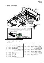
SRS-ZR7
10
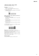
Note:
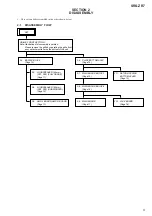
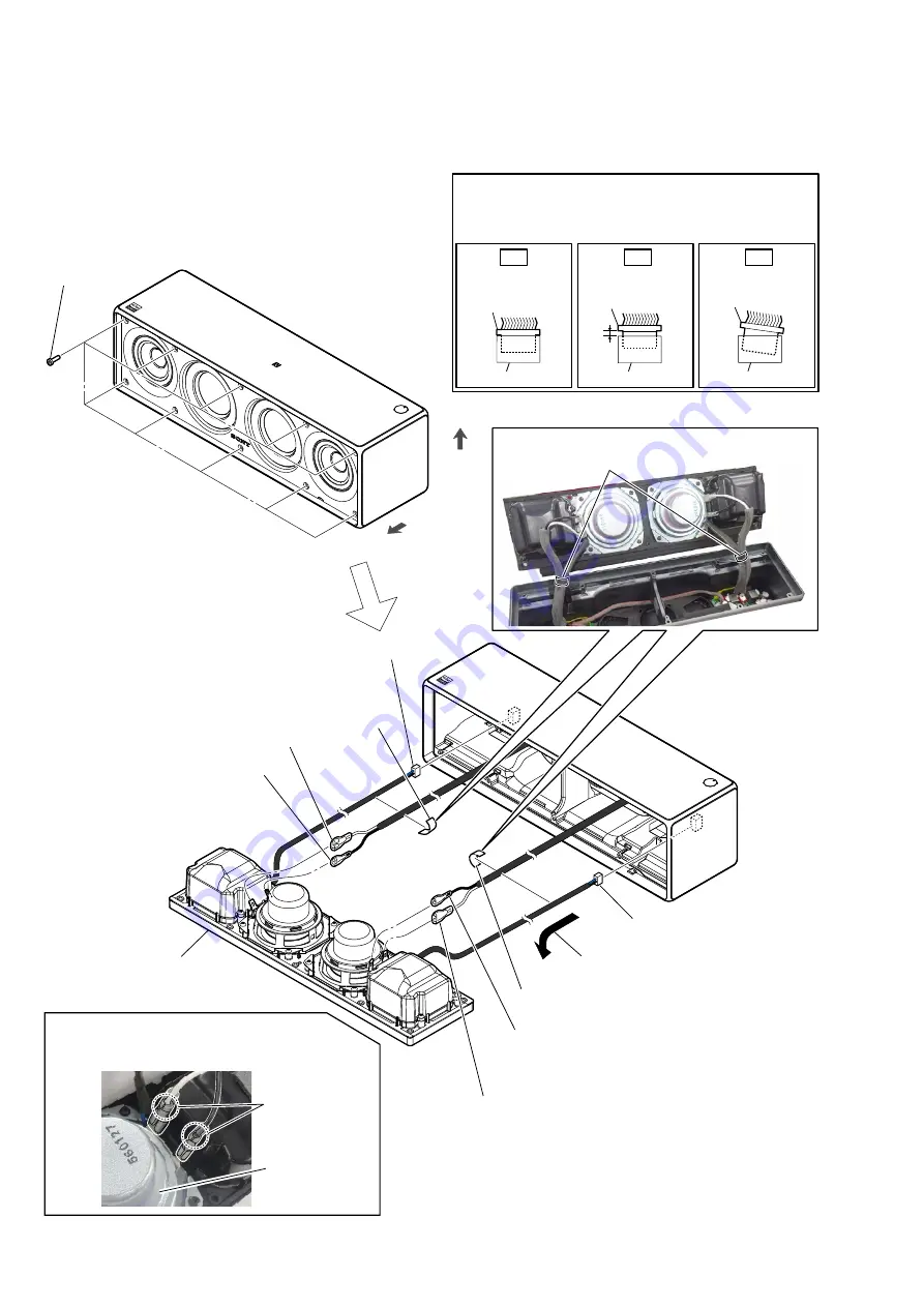
Follow the disassembly procedure in the numerical order given.
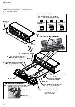
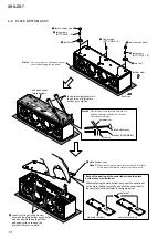
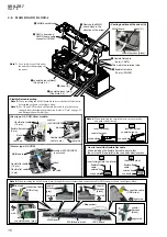
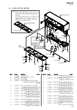
2-2. BAFFLE BLOCK
1
ten screws
(HEX
3
u
10)
3
sheet (B)
3
sheet (B)
2
Draw out the baffle block in
the direction of the arrow.
top side
front side
sheet (B)
,QVWDOODWLRQSRVLWLRQRIWKHVKHHW%
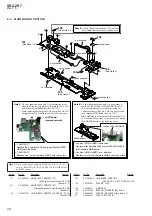
4
R-ch speaker cable connector
(CN853)
5
R-ch subwoofer terminal (narrow) [black]
Note
1:
The terminal is locked firmly.
Please remove the terminal
carefully not to be damaged.
5
R-ch subwoofer terminal (wide) [white]
Note
1:
The terminal is locked firmly.
Please remove the terminal
carefully not to be damaged.
6
baffle block
5
L-ch subwoofer terminal (narrow) [black]
Note
1:
The terminal is locked firmly.
Please remove the terminal
carefully not to be damaged.
5
L-ch subwoofer terminal (wide) [white]
Note
1:
The terminal is locked firmly.
Please remove the terminal
carefully not to be damaged.
4
L-ch speaker cable connector
(CN804)
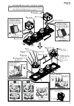
caulking part
speaker unit
,QVWDOODWLRQGLUHFWLRQIRUWKHVSHDNHUZLUH
Note 2:
When installing the speaker wire, toward the caulking
of terminals in the direction of the speaker unit.
Insert only part way.
Insert straight into
the interior.
connector
Insert at a slant.
connector
connector
connector
connector
connector
OK
NG
NG
+RZWRLQVWDOOWKHFRQQHFWRU
Insert the connector straight into the interior.
There is a possibility that using this unit without
the connector correctly installed will damage it.
Summary of Contents for SRS-ZR7
Page 6: ...SRS ZR7 6 MEMO ...
Page 8: ...SRS ZR7 8 MEMO ...


