background image

SLT-A58K/A58M/A58Y_L2

Sony Corporation

SERVICE MANUAL

Revision History

SERVICE  NOTE (Check the following note before the service.)

LEVEL 

2

983473231.pdf

2013C08-1

© 2013.03

Published by Sony Techno Create Corporation

INTERCHANGEABLE LENS DIGITAL CAMERA

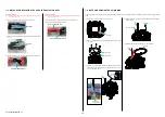
1-1.  METHOD FOR REPLACING THE P.O.I.

1-2.  PRECAUTION ON REPLACING THE AM-1001 BOARD

1-3.   NOTES FOR REPLACING THE EVF DISPLAY DEVICE (LCD902) OR THE AM-1001 

BOARD

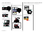
1-4.   ADDITION OF DESTINATION DATA FILE

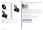
1-5.  METHOD FOR CHECKING THE AS SLIDER UNIT (863)

1-6.  METHOD FOR ADJUSTING THE TEBURE REVISE

1-7.  METHOD FOR REPLACING THE AS SLIDER B ASSY T

1-8.  METHOD FOR REPLACING THE AS HOLDER ACTUATOR ASSY

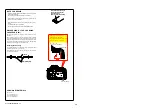
1-9.   NOTE ON REMOVING THE AP IRIS RING

1-10.  HOW TO CHANGE THE APERTURE

1-11.  METHOD OF CONFIRMING THE PHASES OF AP IRIS RING AND AP SENSOR GEAR

9-834-732-31 

[About the service of this model]

SLT-A58K/A58M/A58Y are commodity that packed the Interchangeable Lens Digital Camera and Interchangeable Lenses.
Refer to each following service manual the Interchangeable Lens kit, when you repair.

Model

Lens

Service Manual of Lens

SLT-A58K

SAL1855-2 (DT 18-55mm F3.5-5.6 SAM II)

9-834-733-[]

SLT-A58M

SAL18135 (DT 18-135mm F3.5-5.6 SAM)

9-834-677-[]

SLT-A58Y

SAL1855-2 (DT 18-55mm F3.5-5.6 SAM II)

9-834-733-[]

SAL55200-2 (DT 55-200mm F4-5.6 SAM)

9-852-692-[]

The components identified 
by mark 

0

 or dotted line with 

mark 

0

 are critical for safety.

Replace only with part number 
specified.

Les composants identifiés par 
une marque 

0

 sont critiques 

pour la sécurité.
Ne les remplacer que par une 
pièce portant le numéro spécifié.

SLT-A58K/A58M/A58Y

US Model

Canadian Model

AEP Model

UK Model

Russian Model

E Model

Australian Model

Chinese Model

Korea Model

Photo: SLT-A58 (Main body)

Ver. 1.0  2013.03

Ver.

Date

History

Contents

S.M. Rev.

issued

1.0

2013.03

Official Release

Summary of Contents for SLT-A58K

Page 1: ...4 732 31 About the service of this model SLT A58K A58M A58Y are commodity that packed the Interchangeable Lens Digital Camera and Interchangeable Lenses Refer to each following service manual the Interchangeable Lens kit when you repair Model Lens Service Manual of Lens SLT A58K SAL1855 2 DT 18 55mm F3 5 5 6 SAM II 9 834 733 SLT A58M SAL18135 DT 18 135mm F3 5 5 6 SAM 9 834 677 SLT A58Y SAL1855 2 D...

Page 2: ...m 5 images per second Maximum 2 5 images per second Our measurement conditions The speed of continuous shooting may be slower depending on shooting conditions Image size ISO setting High ISO NR or the setting of Lens Comp Distortion The maximum number of continuous shots In Tele zoom Cont Priority AE mode Fine 16 images Standard 19 images In Continuous shooting Fine 7 images Standard 8 images RAW ...

Page 3: ...t Be careful not to tighten screws too much SAFETY CHECK OUT After correcting the original service problem perform the following safety checks before releasing the set to the customer 1 Check the area of your repair for unsoldered or poorly soldered connections Check the entire board surface for solder splashes and bridges 2 Check the interboard wiring to ensure that no wires are pinched or contac...

Page 4: ...st manual to write the adjustment values When replacing AM board in case adjustment values can be read 1 In case the unrepaired unit starts and adjustment values can be read by using the Adjust manual execute ADJUSTMENT DATA BACKUP on the DATA tab 2 After the AM board has been replaced with a AM board for repair execute ADJUSTMENT DATA BACKUP on the DATA tab of the Adjust manual to write the extra...

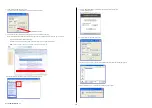
Page 5: ...File For DSC WX50 zip Furthermore the version supported by the Destination Data file is shown in the Remarks column Note If the Destination Data file has not been updated contact the Service Headquarters 4 Download the Destination Data file of the relevant model and unzip the file 5 Execute DESTINATION DATA WRITE in the Adjust tab of the Adjust manual Click the START button 6 Click the File Update...

Page 6: ...ponent part corresponding to the movement 1 6 METHOD FOR ADJUSTING THE TEBURE REVISE Make sure to confirm below after replacing the AS Slider B Assy T or the AS Holder Actuator Assy 1 Remove the Rear Cover Section temporally mount the AS Slider Unit 863 mounted with the Imager Sensor and then set up the camera body and hold the AS Slider Unit 863 as shown in figure 2 Select Slider Unit Check of th...

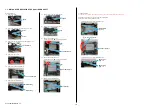
Page 7: ... Yaw Cap 9 Remove the AS Slider AAssy It can be done easily if A is removed beforehand AS Slider AAssy A 10 Remove the AS Slider B Assy T It can be done easily if B is removed beforehand AS Slider B Assy T B 11 Remove the three Ball Bearings Ball Bearings Assembly Procedure Note Make sure to perform the assembly procedures after assembling the AS Holder Actuator Assy The assembly procedure is the ...

Page 8: ...cated below AS Holder Actuator Assy A G G 15 and G G 116 1 9 NOTE ON REMOVING THE AP IRIS RING If the AP Iris Ring is removed the aperture charge cannot be retained Therefore after removing the AP Iris Ring retain the charge in the procedure below 4 While keeping the pin inserted remove the Ring Roller B and AP Ring Roller C Pin AP Ring Roller C Ring Roller B 5 While keeping the pin inserted remov...

Page 9: ...p of pin in the cut portion of AP Sensor Gear to fix the AP Sensor Gear Pin Pin Cut portion of AP Sensor Gear 5 While keeping the pin inserted install theAPAperture Unit aligning the mark of AP Aperture Ring with the center the position where the mark is overlapped within the range in the figure of projection of limit gear assembly Pin The gap exists This line is parallel and contacts the right si...

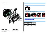
Page 10: ...0 are critical for safety Replace only with part number specified Les composants identifiés par une marque 0 sont critiques pour la sécurité Ne les remplacer que par une pièce portant le numéro spécifié When indicating parts by reference number please include the board name Bottom View Top View Back View Right View Left View Front View View Position ACCESSORIES DISCHARGING OF THE CHARGING CAPACITO...

Page 11: ...he charging capacitor is charged up to the maximum 315 V potential There is a danger of electric shock by this high voltage when the capacitor is handled by hand The electric shock is caused by the charged voltage which is kept without discharging when the main power of the unit is simply turned off Therefore the remaining voltage must be discharged as described below Preparing the Short Jig To pr...

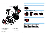
Page 12: ...460 615 01 CV JACK LID 876 2 2 635 562 31 SCREW M1 7 12 3 080 204 21 SCREW TAPPING P2 112 2 178 410 11 TITE UB TITE 1 4 DISCHARGING OF THE CHARGING CAPACITOR 5 2 112 X 1 3 12 Back View 2 Bottom View 12 Right View 12 Left View 3 12 X 2 2 X 3 12 X 3 Open the Jack Lid 3 12 X 4 Screw 2 M1 7 X 4 0 Black 2 635 562 31 4 0 1 7 12 M1 7 X 5 0 Tapping Black 3 080 204 21 1 7 5 0 112 M1 4 X 5 0 Black 2 178 410...

Page 13: ... 21 SCREW TAPPING P2 140 2 635 562 01 SCREW M1 7 A A G F F G E E B B C C 2 Main Board Section See page 2 5 Strobe Base VF Lens Section See page 2 10 Strobe Base VF Lens Section See page 2 10 12 12 2 12 12 5 5 5 2 140 1 51 52 2 54 55 58 53 57 56 Claw Claws Claw 3 4 DISASSEMBLY 1 Remove in numerical order 1 to 4 in the left figure Bottom View 12 3 2 X 4 1 12 X 1 2 Top View Bottom View Front View Lef...

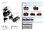
Page 14: ...crew 5 M1 7 X 3 5 Tapping Black 3 080 204 01 3 5 1 7 12 M1 7 X 5 0 Tapping Black 3 080 204 21 1 7 5 0 109 M1 7 X 3 0 Black 2 515 483 21 3 0 1 7 Shutter Unit Section See page 2 6 BT3101 Note BH3101 Note ns 12 109 12 12 12 5 A B C D E F G I H K J A B C D I J K H G F E 101 3 102 103 2 104 105 4 107 1 106 BT3101 BATTERY LITHIUM SECONDARY Board on the mount position See page 6 34 of Level 3 Size 11 0mm...

Page 15: ... 154 A 1869 165 A ALX 8631 Note 2 including AF 131 flexible complete board 155 2 693 420 01 SP S ADJUSTMENT J901 1 821 194 51 JACK DC SP901 1 826 403 61 LOUDSPEAKER 1 0CM 12 3 080 204 21 SCREW TAPPING P2 207 4 191 605 01 S ADJUSTMENT SCREW 4 207 X 3 Top View 207 207 M1 6 X 8 0 Silver 4 191 605 01 8 0 1 6 SP901 J901 12 12 12 A A 151 1 152 153 Note 1 3 Imager Section See page 2 7 2 Battery Holder Se...

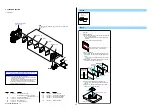
Page 16: ...acer from the imager Pour resolvent alcohol or cleaning agent between the imager and the IM spacer Method of Attachment 1 Attach the IM GS tape and the Optical filter block by aligning them with the outer shape of the IM GS tape evenly The two layer side of the Optical filter block is on the imager side 2 Attach the IM spacer fixed tape by aligning it with the outer shape of the IM GS tape evenly ...

Page 17: ...M1 7 X 2 5 Silver 2 599 475 11 2 5 1 7 B B A A ns ns ns ns ns ns ns ns ns 252 252 251 including HOL 007 flexible complete board Note 1 2 Note 3 253 Note 4 254 255 254 254 254 252 14 14 87 254 Note 1 Refer to 1 5 METHOD FOR CHECKING THE AS SLIDER UNIT 863 on page 1 3 before replasing the AS Slider B Assy T or the AS Holder Actuator Assy Note 2 Refer to 1 6 METHOD FOR ADJUSTING THE TEBURE REVISE on ...

Page 18: ...R 871 308 4 424 467 01 CV LCD FPC GUARD B 871 309 X 2584 216 1 CV P CABINET C ASSY 871 310 1 888 340 11 LCD 2002 FLEXIBLE BOARD 311 A 1933 716 A PD 1017 BOARD COMPLETE 312 4 460 649 01 EM LCD BOARD TAPE 876 313 4 424 893 01 EM LCD INSULATING TAPE 871 314 4 423 394 01 EM LCD UNIT CASE 871 LCD901 A 1943 506 A LCD BLOCK ASSY SERVICE 2 2 635 562 31 SCREW M1 7 12 3 080 204 21 SCREW TAPPING P2 Screw 12 ...

Page 19: ...OR 2P Yellow 361 X 2587 047 1 BD SHOE FRAME ASSY 876 362 A 1933 718 A SHM 2000 FLEXIBLE BOARD COMPLETE 363 X 2587 048 1 ST BASE ASSY 876 364 4 293 682 01 IM SHEET RADIATION 365 X 2586 488 1 VM VF LENS ASSY 876 366 A 1933 720 A EYE 012 FLEXIBLE BOARD COMPLETE 367 4 460 634 01 ST SWITCH PLATE 876 LCD902 8 753 379 22 ECX333AA 1 MIC901 1 542 899 21 MICROPHONE UNIT PL901 1 455 061 11 SOLENOID PLUNGER 2...

Page 20: ...IA COVER 876 410 4 293 658 01 CV MEDIA LID COVER SP 411 4 293 652 01 BD BATTERY LOCK 412 4 293 654 01 BD BATTERY LOCK SHAFT 413 4 293 653 01 BD BATTERY LOCK SP 414 4 293 662 01 BD BT LID COVER SHAFT 415 X 2582 396 1 BD BATTERY LID ASSY BT901 1 780 588 21 TERMINAL BOARD BATTERY C901 1 116 522 11 CAP ELECT 180uF 330V 2 2 635 562 31 SCREW M1 7 5 3 080 204 01 SCREW TAPPING P2 DISASSEMBLY 1 The meaning...

Page 21: ...HEAD PAN TAPPING 295 2 695 575 21 SCREW T2 P1 PAN TAPPNG Note Screw 2 1 10 MIRROR BOX SECTION SUB UNIT 1 ns not supplied 295 23 23 164 ns ns 165 165 Mirror Box Section Sub Unit 2 See page 2 13 461 including M902 aperture motor and AP 037 flexible complete board Note 3 473 including M901 AF motor and AFP 007 flexible complete board 462 including BL 038 flexible board 453 455 456 Note 3 467 460 Note...

Page 22: ...512 4 292 574 01 MB LENS LOCK BASE PLATE 513 4 292 585 01 MB AF MF SELECTION LEVER 23 3 080 204 11 SCREW TAPPING P2 241 3 703 816 46 SCREW M1 4X2 5 SPECIAL HEAD 2 1 11 MIRROR BOX SECTION SUB UNIT 2 ns not supplied Note Screw 23 M1 7 X 4 0 Tapping Black 3 080 204 11 4 0 1 7 241 M1 4 X 2 5 Black 3 703 816 46 2 5 1 4 ns ns ns 23 241 23 23 23 503 Note 1 504 Note 1 2 502 513 509 510 501 508 507 512 506...

Page 23: ...on Manual CZECH 914 4 459 709 41 Instruction Manual THAI 914 4 459 709 51 Instruction Manual INDONESIAN 915 4 459 705 11 α Handbook ENGLISH Note 1 Ref No Part No Description 915 4 459 705 21 α Handbook FRENCH Note 1 915 4 459 705 31 α Handbook ITALIAN Note 1 915 4 459 705 41 α Handbook SPANISH Note 1 915 4 459 705 51 α Handbook PORTUGUESE Note 1 915 4 459 705 61 α Handbook GERMAN Note 1 915 4 459 ...

Page 24: ...ing Position MB Shutter Charge SP MB Shutter Charge Camgear Assy MB Shutter Charge Lever MB Lever Cushion MB Deceleration Gear 1 MB Deceleration Gear 2 Assembly 3 Mirror Box Sub Unit 3 1 Ring Roller A SV AP Iris Ring A Attach the Ring Roller A SV to the MB Front Frame Assy When attaching the Ring Roller A SV be sure to remove the AP Iris Ring beforehand B Attach the AP Iris Ring by aligning it wit...

Page 25: ...o not slide from right to left or up and down while dabbing 3 Repeat 3 several times to clean up 4 According to the service manual check if there is dirt on the OLPF CCD Cleaning Jig New J 6082 663 A CCD Cleaning Jig CCD Cleaning Jig Tip Protection Sheet Cleaning Procedure for Tip of CCD Cleaning Jig 1 Put the two cleaning cloths on a tray like below 1 Souse the one cleaning cloth in ethyl alcohol...

Reviews: