background image

SFM2


Page - 10 -  

Installation Manual 

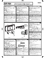
Attaching the Display to the Backplate 

NOTE

:  For clarity purposes, the following illustrations will be shown without the adapter plate and display 

attached. This must be done to show how the positioning of the backplate cover and the backplate 
relate to each other (connection-wise). 

1.  The flange opening must be facing up.  
2.  Raise the flat panel with the front plate attached and slide the top flange opening to the flange on the 

backplate (Figure 7).  

3.  Slide the monitor down slowly. Make sure the backplate flange captures the frontplate top flange opening 

before letting go of the monitor. Slide down and push in (Figure 8).  

4.  To secure the two plates, tighten the two (2) M6 x 12 (mm) security screws using a long Phillip head 

screwdriver (Figure 9).  


Figure 7


Figure 8


Figure 9


Flange 

Frontplate 

Backplate 

Flange Opening 
(Slot opening 
on top of 
frontplate) 

Simulated Display 

M6 x 12mm 
Security Screws 

Summary of Contents for SFM2

Page 1: ...IN SFM2 R1 INSTALLATION MANUAL SFM2 Sony Electronics Inc 16540 West Bernardo Drive San Diego CA 92127 www sony com ...

Page 2: ...NSTALLATION PROCEDURES 5 SINGLE STUD INSTALLATION 5 SOLID STRUCTURE INSTALLATION 6 ATTACHING THE ADAPTER PLATE AND THE BACKPLATE COVER 7 ATTACHING THE ADAPTER PLATE BACKPLATE COVER TO THE DISPLAY 9 ATTACHING THE DISPLAY TO THE BACKPLATE 10 TECHNICAL SPECIFICATIONS 11 WARRANTY 12 CUSTOMER SUPPORT 12 NOTES 12 ...

Page 3: ...THESE INSTALLATION INSTRUCTIONS IN AN EASILY ACCESSIBLE LOCATION FOR FUTURE REFERENCE Indicates that the power plug is to be disconnected from the power outlet Contact Sony Electronics with any questions Safety precautions must be taken at all times Warning and Caution statements Do not install on a structure that is prone to vibration movement or chance of impact Failure to do so could result in ...

Page 4: ... Phillips Pan Head Screw Qty 4 10 x 1 1 4 Wood Screws Qty 4 M6 x 12mm Security Screws Qty 2 6 32 x 1 Slotted Screw Qty 2 M6 x 10mm Phillips Head Screws Qty 4 10 Anchors Qty 4 For use with the following Sony models SONY FWD 32LX1 FWD 32LX1R NOTE Prior to installing the SFM2 the quick release sleeves located on the back of the display must be removed After removing them please store them in a safe l...

Page 5: ...ds use the two middle mounting points found on the back plate Figure 1 2 Locate the center of the wood stud behind the wall mark the height and desired location 3 Drill two 1 4 pilot holes on the marked wall 4 Secure the back plate to the center of the wood stud by using two 2 10 wood screws Figure 1 NOTE Four wood screws will be used when mounting the backplate to a solid structure Page 7 Also al...

Page 6: ...ing points found on the back plate 4 Drill four 4 1 4 pilot holes for the plastic anchors then secure the wall bracket with the four 4 10 x 1 screws supplied to the anchors NOTE All electrical wiring should be done at this time Use the two 2 6 32 x 1 handy box screws supplied for your installation needs Figure 2 10 Wood Screws 10 Wood Screws 10 Wood Screws 10 Wood Screws Electrical Opening Frontpl...

Page 7: ...ead screws Figure 4 3 Do not tighten the screws until all four are inserted 4 Once the screws are inserted tighten the screws down CAUTION Do not over tighten the M4 screws to the monitor Failure to do so could result in damaging the threads and monitor 5 At this time loosely install the two 2 M6 x 12mm Security Screws Figure 4 Figure 3 Mounting Box Adapter Plate Combination Adapter Plate Frontpla...

Page 8: ...SFM2 Page 8 Installation Instructions Figure 4 M4 x 10mm Phillips Head Screws M4 x 10mm Phillips Head Screws M6 x 12mm Phillips Head Security Screws Adapter Plate Frontplate ...

Page 9: ...urface and locate the four mounting points Figure 5 2 Attach the Adapter Plate to the back of the display using four 4 M6 x 10mm Phillips Head screws Figure 6 Do not overtighten the screws CAUTION DO NOT OVERTIGHTEN THE SCREWS Figure 5 Installing the Adapter Plate Mounting Box Figure 6 Installation Complete Ultra Flat Mount Adapter Plate ...

Page 10: ...e the flat panel with the front plate attached and slide the top flange opening to the flange on the backplate Figure 7 3 Slide the monitor down slowly Make sure the backplate flange captures the frontplate top flange opening before letting go of the monitor Slide down and push in Figure 8 4 To secure the two plates tighten the two 2 M6 x 12 mm security screws using a long Phillip head screwdriver...

Page 11: ...SFM2 Installation Manual Page 11 Technical Specifications Figure 7 Adapter Plate 750 4 750 5 750 5 3125 VESA 100 VESA 75 Figure 8 Ultra Flat Mount ...

Page 12: ...le for improper installation that results in damage to mounts adapters display equipment or personal injury Customer Support In the event of missing and or damaged equipment or technical questions the following information can help in the completion of the installation Customer Service 877 350 3477 Notes Sony Electronics Inc 16540 West Bernardo Drive San Diego CA 92127 800 350 3477 www sony com So...

Reviews: