

SDM-S51(E)
2-4
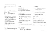
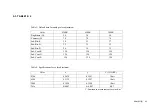
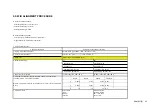
2-4. TIMING SPECIFICATION
PRESET MODE
MODE 1
MODE 2
MODE 3
MODE 4
MODE 5
MODE 6
MODE 7
MODE 8
SIGNAL MODE
VESA 60Hz
MAC 13”
VESA 75Hz
VESA 85Hz
VESA 70Hz
VESA 60Hz
VESA 75Hz
VESA 85Hz
RESOLUTION
640 X 480
640 X 480
640 X 480
640 X 480
720 X 400
800 X 600
800 X 600
800 X 600
DOT CLOCK
25.175 MHz
30.240 MHz
31.500 MHz
36.000 MHz
28.350 MHz
40.000 MHz
49.500 MHz
56.250 MHz
HORIZONTAL usec usec usec usec usec usec usec usec
H.
TOATL
31.778 28.571 26.667 23.111
31.746 26.400 21.333 18.631
H.
SYNC
3.813 2.116 2.032 1.556 2.540 3.200 1.616 1.138
H.
BP
1.907 3.175 3.810 2.222
3.175 2.200 3.232 2.702
H.
ACTIV
25.422 21.164 20.317 17.778
25.397 20.000 16.162 14.222
VERTICAL msec
msec
msec
msec
msec
msec
msec
msec
V.
TOTAL
16.683 15.000 13.333 11.764
14.254 16.579 13.333
11.756
V.
SYNC
0.064 0.086 0.080 0.069
0.095 0.106 0.064
0.056
V.
BP
1.049 1.114 0.427 0.578 1.079 0.607 0.448 0.503
V.
ACTIV
15.253 13.714 12.800 11.093
12.698 15.840 12.800
11.179
H/V
POLARITY
N/N N/N N/N N/N N/P P/P P/P P/P
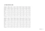
PRESET MODE
MODE 9
MODE 10
MODE 11
MODE 12
MODE 13
SIGNAL MODE
PMAC 16”
VESA 60Hz
VESA 70Hz
VESA 75Hz
75Hz
RESOLUTION
832 X 624
1024 X 768
1024 X 768
1024 X 768
1024 X 768
DOT CLOCK
57.285 MHz
65.000 MHz
75.000 MHz
78.750 MHz
94.500 MHz
HORIZONTAL usec usec usec usec usec
H.
TOATL
20.110 20.677 17.707 16.660 14.561
H.
SYNC
1.117 2.092 1.813 1.219 1.016
H.
BP
3.910 2.462 1.920 2.235 2.201
H.
ACTIV
14.524 15.754 13.653 13.003 10.836
VERTICAL msec
msec
msec
msec
msec
V.
TOTAL
13.413 16.666 14.272 13.328 11.765
V.
SYNC
0.060 0.124 0.106 0.050 0.044
V.
BP
0.744 0.600 0.513 0.466 0.524
V.
ACTIV
12.549 15.880 13.599 12.795 11.183
H/V
POLARITY
N/N N/N N/N P/P P/P
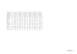
MODE 14
MODE 15
MODE 16
PMAC 19”
MAC
WS
1024 X 768
1152 X 870
1152 X 900
80.000 MHz
100.000 MHz
92.940 MHz
usec usec usec
16.600
14.560 16.182
1.200
1.280
1.377
2.200
1.440
2.087
12.800
11.520 12.395
msec
msec
msec
13.346
13.322 15.163
0.050
0.048 0.065
0.498
0.568 0.502
12.749
12.667 14.564
N/N N/N N/N
VESA


