background image

HELP

SAL135F18Z (Sonnar 1.8/135 ZA) (Sonnar T

*

 135mm F1.8 ZA)

HELP16

Adhesive bond (B-40): J-6082-614-A

1.

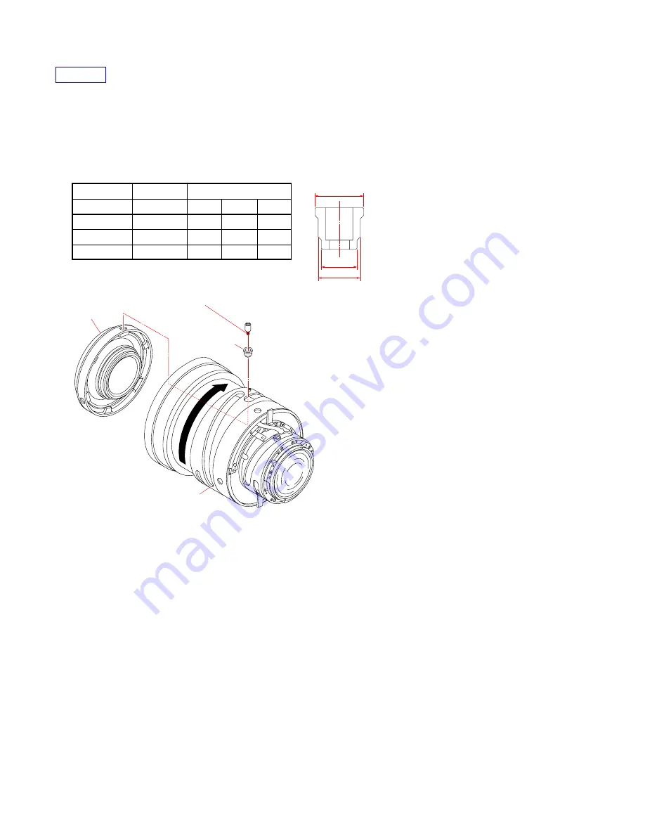
Rotate the focus cam ring assy to allowed direction, set to the near position.

2.

Install the 2 lens block to the length grove barrel assy side. Apply the adhesive bond (B-40) to the screwed portions of 2 roller screws.

Then, fix the 2 group lens block with the 2 roller and the 2 roller screws at three locations.

Note:

Select the 2 roller with a play of 0 to 0.010mm with respect to the groove width of length grove barrel assy.

Part Code

Part Name

Diameter

D1

D2

D3

2-897-888-01

2 C roller

3.99

4.50

3.50

2-897-889-01

2 K roller

4.00

4.52

3.50

2-897-890-01

2 L roller

4.01

4.53

3.50

3.

Confirm that the focus 1 cam ring assy rotates smoothly.

D2

D3

D1

2 Lens Block

2 Roller 
(3 places)

Focus 1 Cam Ring Assy

2 Roller Screw
(Apply the adhesive bond (B-40) (3 places))

Summary of Contents for SAL-135F18Z - 135mm f/1.8 Carl Zeiss Sonnar T Telephoto Lens

Page 1: ...135mm F1 8 ZA Ver 1 4 2007 12 LENS FOR DSLR CAMERA 2007L0800 1 2007 12 Published by Kohda TEC 9 852 110 12 US Model Canadian Model AEP Model Chinese Model SAL135F18Z Sonnar 1 8 135 ZA Sonnar T 135mm F1 8 ZA About the Special Driver About the Lens Test Projector and Finished Inspection JIG About the Screw Filter Frame Assy About the MTF measurement Revised 1 Replace the previously issued SERVICE MA...

Page 2: ... APS C sized image sensor Lens groups elements 8 11 Angle of view 1 2 18 Angle of view 2 2 12 2 The value of angle of view 1 is based on 35mm format cameras and that of angle of view 2 is based on Digital Single Lens Reflex Cameras equipped with an APS C sized image sensor Minimum focus m feet 3 0 72 2 4 3 Minimum focus is the shortest distance from the image sensor to the subject Maximum magnific...

Page 3: ...d Views 3 1 3 2 Supplied Accessories 3 4 4 ADJUSTMENTS 4 1 Preparations 4 1 4 2 Aperture Diameter Check Adjustment 4 13 4 3 Projective Resolving Power Check 4 20 4 4 Flange Back f F Check Adjustment 4 23 4 5 Focus Shift Check Adjustment Aperture 4 26 4 6 Torque Ring Play Adjustment 4 27 4 7 Lens ROM Check 4 28 4 8 Focus Brush Position Check Adjustment 4 30 4 9 Focus Hold Button Check Focus Hold Bu...

Page 4: ...to clean heavy dirt don t use paint thinner ketone nor alcohol Insert the specific screws vertically to the part when installing a exterior part Be careful not to tighten screws too much 1 3 Unleaded Solder This unit uses unleaded solder Boards requiring use of unleaded solder are printed with the lead free mark LF indicating the solder contains no lead Caution Some printed circuit boards may not ...

Page 5: ...ing iron on the same conductor of the circuit board within 3 times Be careful not to apply force on the conductor when soldering or unsoldering SAFETY RELATED COMPONENT WARNING COMPONENTS IDENTIFIED BY MARK 0 OR DOTTED LINEWITH MARK 0 ON THE SCHEMATIC DIAGRAMS AND IN THE PARTS LIST ARE CRITICAL TO SAFE OPERATION REPLACE THESE COMPONENTS WITH SONY PARTS WHOSE PART NUMBERS APPEAR AS SHOWN IN THIS MA...

Page 6: ...rt Check operation of the preset ring and replace the defective part Perform the aperture diameter adjustment See page 4 16 Perform the aperture diameter check See page 4 13 NG Check operation of the diaphragm control block OK OK OK Function NG F No NG Aperture trouble Replace the defective part NG NG NG END OK Perform the aperture diameter check See page 4 13 ...

Page 7: ...e defective part or apply the grease Check the coupler Check the focus 1 cam ring assy and focus 2 cam ring block NG NG NG NG NG END OK Check the installation of the F ECD flexible Reinstall the F ECD flexible Check pattern of the F ECD flexible Clean the pattern of the F ECD flexible Replace the F ECD flexible Perform the focus brush position check adjustment See page 4 30 1 5 2 Focus Trouble ...

Page 8: ...ed flexible board UNIVERSAL WRENCH In case of the following notches or holes are located in the lens block etc during disassembling assembling the lens Use the universal wrench How to Use Attach the chip A or chip B to the universal wrench For the notches chip A For the holes chip B Match the universal wrench to the holes or notches of the lens block etc When top of tip does not reach holes or not...

Page 9: ...A Note 2 When removing or installing the parts of side of lens mount install the filter screw frame to lens If removing or installing the parts of side of lens mount after the filter screw frame is removed be careful to avoid damaging the 1 lens block Note 3 Remove the screw Ref No 15 or 61 2 897 949 01 screw 3ULR F M1 7x1 6 C3C using the special driver Special driver J 6082 654 A Shape of head ...

Page 10: ...k 6 Mount Block Outer Barrel Block 7 Coupler Receive APERTURE DIAMETER ADJUSTMENT FLANGE BACK ADJUSTMENT TOUQUE RING PLAY ADJUSTMENT In case the removing of screw filter frame assy Before removing the screw filter frame assy lubricate a small solvent alcohol to a gap between screw filter frame assy and draw ring assy hereby dissolve the adhesive bond Then remove it About the screw filter frame ass...

Page 11: ...Iris Block PROJECTIVE RESOLVING POWER CHECK 6 3 Lens Block HELP19 7 4 Lens Block PROJECTIVE RESOLVING POWER CHECK 8 Scale Focus Sheet 3 Zoom Brush FOCUS BRUSH POSITION CHECK In case the installing of 1 lens block Install the 1 lens block placed with same position of removing it to the length grove barrel assy When removing the 1 lens block put the marks of both the 1 lens block and length grove ba...

Page 12: ...mm width to the location shown in figure of draw ring assy 2 Aligning the inner cut portions at three locations with the guide pins install the screw filter frame assy with the print of 1 8 135 placed at the distance scale window side HELP Draw Ring Assy Apply the adhesive bond B 10 width 10mm Apply the adhesive bond B 10 width 10mm Screw Filter Frame Assy Inner Cut Portions Guide Pin Guide Pins D...

Page 13: ...as it goes and stops HELP02 Adhesive bond B 40 J 6082 614 A 1 Install the draw ring assy 2 Apply the adhesive bond B 40 to the tip of three guide pins and tighten them Guide Pins Apply the adhesive bond B 40 Guide Pins Apply the adhesive bond B 40 Draw Ring Assy Filter screw frame removing tool Ver 1 4 2007 12 The changed portions from Ver 1 3 are shown in blue ...

Page 14: ...ck HELP03 Adhesive bond B 10 J 6082 612 A 1 Install the focus ring and tighten three screws to fix it 2 Apply the adhesive bond B 10 to the heads of screws HELP04 Adhesive bond B 40 J 6082 614 A 1 Install the rear light shiled ring block apply the adhesive bond B 40 to the screws and tighten three screws Note Be careful not to drop screws in the lens 2 Confirm that the preset ring moves smoothly ...

Page 15: ...sive bond B 40 J 6082 614 A Install the contact flexible Apply the adhesive bond B 40 to the screwed portions of screws and tighten two screws to fix the contact flexible Note Be careful not to drop screws in the lens Screws Apply the adhesive bond B 40 Contact Flexible ...

Page 16: ...rs selected in the adjustment aligning their cut portions Then apply the grease G 35 to the cut portion of washer on the top 2 After inserting the shaft of coupler in the cut portion of FB adjustment washer install it to the lens Note Place the golden FB adjustment washer on the side of mount Be careful not drop the coupler FB Adjustment Washer Cut Portions FB Adjustment Washer Gold Apply the grea...

Page 17: ...ve bond B 40 to the screwed portions of screws Then tighten four screws to fix the mount block Note Before installing the mount block confirm that the white coupler receive is inserted in the hole for coupler installation After tightening the screws confirm that the coupler rotates when the focus ring is rotated Mount Block Coupler Coupler Receive Holes for coupler installation Screws Apply the ad...

Page 18: ... 10 J 6082 612 A 1 Install the contact flexible guide and tighten two screws to fix it 2 Apply the adhesive bond B 10 to the heads of screws 3 Install the writing flexible of contact block to the contact board guide with two screws 4 Apply the adhesive bond B 10 to the heads of screws Install the writing flexible Contact Flexible Guide Screws Apply the adhesive bond B 10 ...

Page 19: ...her end to lever of main spring guide 2 Fix the main spring guide with two screws Note When installing the main spring guide place the main spring in the inner side of cut and elected portion 3 Apply the adhesive bond B 10 to the heads of screws 4 Confirm that the preset ring moves smoothly Main Spring Preset Ring Main Spring Guide Screws Apply the adhesive bond B 10 ...

Page 20: ...f focus hold barrel block to the index hole of the rear ring assy Note After installing confirm that the index pin is securely inserted in the index hole 5 Fix the rear ring assy with four screws tightening screws in orders shown in figure Note After installing the function lever confirm that the iris opens and closes when the lever of preset ring is turned 6 Apply the adhesive bond B 10 to the he...

Page 21: ... J 6082 612 A 1 Install so that align the index pin of focus hold barrel block to the index hole of the rear ring assy Note After installing confirm that the index pin is securely inserted in the index hole 2 Fix the rear ring assy with four screws tightening screws in orders shown in figure 3 Apply the adhesive bond B 10 to the heads of four screws Note Apply the adhesive bond to the outer diamet...

Page 22: ... 0 05 Preset Ring B 2 898 007 11 9 49 0 05 Preset Ring C 2 898 007 21 9 74 0 05 Amount of FB adjustment washer 0 1 Preset ring to be used 0 1 A 0 2 A 0 3 A or B 0 4 B 0 5 B 0 6 C 0 7 C 0 8 C 1 Measure the thickness of FB adjustment washers used in the flange back adjustment with micrometer or caliper Depending on the measured thickness select the preset ring from the table 2 Aligning four cut port...

Page 23: ...ens install the function lever to the preset ring and fix it tentatively in the center of oblong hole with two screws Use the special driver J 6082 654 A Note After installing the function lever confirm that the iris opens and closes when the lever of preset ring is turned 5 Adjust the aperture diameter Refer to 4 2 6 After adjust the aperture diameter apply the adhesive bond B 10 to the tip of sc...

Page 24: ...fix it 3 Apply the adhesive bond B 10 to the heads of screws 4 Connect the F ECD flexible and FH button main flexible to the connectors of main board Note To prevent the wire cutting from occurring bend the flexible board perpendicularly After connecting confirm that the connector is securely locked FH Button Main Flexible F ECD Flexible Focus Hold Barrel Block FH Button Main Flexible Connector Co...

Page 25: ... ZA Sonnar T 135mm F1 8 ZA Apply the grease G 35 All round Length Grove Barrel Assy HELP12 Adhesive bond B 10 J 6082 612 A Grease G 35 J 6082 621 A 1 Apply the grease G 35 to the location shown in figure of length grove barrel assy ...

Page 26: ...am joint ring of focus hold barrel block 5 Tightening four screws white screws 1 to 4 in figure and five screws black screws 1 to 4 in figure in orders shown in figure fix the outer barrel block to the length grove barrel assy 6 Apply the adhesive bond B 10 to the heads of nine screws 7 Perform the torque ring play adjustment Refer to 4 6 Screw Black Apply the adhesive bond B 10 Screw White Apply ...

Page 27: ...ive bond B 10 the head of hexagon bolt at the length grove barrel assy side Note Be careful for the adhesive bond not to seep out to the outer diameter side of length grove barrel assy HELP14 Peel off the detached paper from the 2nd ornamental sheet and affix it to the location specified in figure 2nd Ornamental Sheet 2 Lens Block Length Grove Barrel Assy 1 Lens Block Hexagon bolt Apply the adhesi...

Page 28: ...the focus 1 cam ring assy in the arrow direction to make the infinity end 2 Install the zoom brush and tighten two screws to fix it Use the special driver J 6082 654 A 3 Confirm that the brush securely contacts the trace on F ECD flexible and has no bending 4 Perform the adjustment of focus brush position Refer to 4 8 5 After finishing the position adjustment apply the adhesive bond B 10 to the lo...

Page 29: ...e 2 group lens block with the 2 roller and the 2 roller screws at three locations Note Select the 2 roller with a play of 0 to 0 010mm with respect to the groove width of length grove barrel assy Part Code Part Name Diameter D1 D2 D3 2 897 888 01 2 C roller 3 99 4 50 3 50 2 897 889 01 2 K roller 4 00 4 52 3 50 2 897 890 01 2 L roller 4 01 4 53 3 50 3 Confirm that the focus 1 cam ring assy rotates ...

Page 30: ...en fix the iris block with the 3 roller and the 3 roller screws at three locations Note When assembling do not touch the iris blades Select the 3 roller with diameter 0 to 0 010mm that is a little larger than the diameter of a hole of length grove barrel assy And press and fit it in the hole Part Code Part Name Diameter D1 D2 D3 2 897 899 01 3 A roller 3 99 4 50 3 48 2 897 900 01 3 D roller 3 99 4...

Page 31: ...portions of 3 roller screws Then fix the 3 group lens block with the 3 roller and the 3 roller screws at three locations Note When assembling do not touch the lens Use the 3 roller with a play of 0 to 0 010mm with respect to the groove width of length grove barrel assy Part Code Part Name Diameter D1 D2 D3 2 897 899 01 3 A roller 3 99 4 50 3 48 2 897 900 01 3 D roller 3 99 4 51 3 48 3 Confirm that...

Page 32: ...4 A 1 Affix the focus scale to meet the length grove barrel assy vertical horizontal Note Confirm that the focus scale is not floated Confirm that the surface of focus scale is clean 2 Expose both ends of focus scale by peeling off the protection tape so that screws can be tightened 3 Fix the focus scale with two screws Use the special driver J 6082 654 A 4 Apply the adhesive bond B 10 to the head...

Page 33: ...A ASSY PWB FLEXIBLE MAIN 10 2 898 117 01 SCREW 2P 1 7X2 2 BNI 11 A 1224 099 A RING ASSY REAR 12 2 695 839 01 LABEL MODEL NAME NOTE XX and X mean standardized parts so they may have some difference from the original one Items marked are not stocked since they are seldom required for routine service Some delay should be anticipated when ordering these items The mechanical parts with no reference num...

Page 34: ... 01 SCREW HEXAGONAL M2X5 5 C3C 60 X 2177 204 1 LENGTH GROVE BARREL ASSY Note 2 61 2 897 949 01 SCREW 3ULR F M1 7X1 6 C3C Note 3 Ref No Part No Description Note 2 Refer to page 3 3 for detail of parts of the length grove barrel assy Ref No 60 62 Selection parts WASHER A B D TILT ADJUSTMENT Note 1 63 A 1224 069 A LENS BLOCK 4 64 2 897 887 01 SCREW 2P 1 7X4 BNI 65 Selection parts ROLLER C K L 2 Note ...

Page 35: ...TMENT A t 0 02 2 897 851 01 WASHER TILT ADJUSTMENT B t 0 03 2 897 852 01 WASHER TILT ADJUSTMENT D t 0 1 Ref No 65 Select the type of part according to operation load of the associated parts Part No Description 2 897 888 01 ROLLER 2 C D1 3 99 D2 4 50 D3 3 50 2 897 889 01 ROLLER 2 K D1 4 00 D2 4 52 D3 3 50 2 897 890 01 ROLLER 2 L D1 4 01 D2 4 53 D3 3 50 Ref No 67 Select the type of part according to...

Page 36: ...45 01 MANUAL INSTRUCTION JAPANESE ENGLISH FRENCH SPANISH SIMPLIFIED CHINESE 2 685 145 11 MANUAL INSTRUCTION GERMAN DUTCH SWEDISH ITALIAN AEP 2 685 145 21 MANUAL INSTRUCTION PORTUGUESE RUSSIAN ARABIC TRADITIONAL CHINESE KOREAN AEP X 2176 984 1 Rear Lens Cap 2 683 615 01 Lens Case 2 694 834 01 Lens Hood SH0003 2 687 326 01 Front Lens Cap ...

Page 37: ... ESI homepage Fig 4 1 1 4 ADJUSTMENTS J 1 J 10 J 13 J 16 J 11 J 9 J 12 J 15 J 7 J 2 J 4 J 5 J 14 J 8 J 3 J 6 20 30 40 50 60 70 80 90 0 10 Personal computer Note 1 AE master lens J 6082 597 A Flange back gauge 43 50mm J 6082 608 A Flange back tester J 6082 606 A A mount attachment J 6082 607 A Lens test projector J 6082 605 A Note 3 1000 mm Collimator 110V J 6082 604 A 240V J 6082 604 B Note 2 Lumi...

Page 38: ...rea 15 M Byte or more recommended USB terminal Standard equipment Graphics 32 000 colors or more recommended VGA monitor Note 2 Attach the chart to the 1000 mm collimator as shown in Fig 4 1 2 Fig 4 1 2 Note 3 Connect the variable transformer Output voltage AC 100 V to the lens test projector Note 4 Finished Inspection JIG is AC 100 V only Align the marks 1000 mm collimator Chart ...

Page 39: ...quipment used Personal Computer Lens Adjustment Program ActuatorChecker Ver x x x x zip PC Card Setup File InstaCal zip Note 1 Lap top PC with PC card slot on which Windows XP runs Note 2 Obtain the PC card setup file InstaCal exe from the ESI homepage Note 3 Obtain the lens adjustment program ActuatorChecker Ver x x x x zip from the ESI homepage 1 Download of PC card setup file InstaCal zip 1 Cre...

Page 40: ...xtract destination folder Fig 4 1 5 6 The window returns to the menu to specify the extract destination folder Click Unzip Fig 4 1 6 7 When the window below appears click OK Fig 4 1 7 8 Return to the menu to specify the extract destination folder Then click Close to close the window ...

Page 41: ...2 Setup of PC Card 1 Double click InstaCal msi in C MCC folder to begin the installation Fig 4 1 8 2 The menu to begin the installation appears Click Next Fig 4 1 9 3 Specify the install destination folder As the default is used for it click Next Fig 4 1 10 ...

Page 42: ... The installation is completed Click Finish Note To refer to the readme file check the Show the readme file and click Finish Fig 4 1 12 6 To make the configuration installed effective the window to prompt the restart appears Click Yes to restart the PC Note If a device is connected without restarting the program may not work properly Fig 4 1 13 ...

Page 43: ... PC insert the PC CARD DIO48 in the PC card slot 8 The software installation window appears Click Install the software automatically Recommended Fig 4 1 14 9 The software is detected and installed When the window below appears click Finish to terminate the installation Fig 4 1 15 ...

Page 44: ... on the Windows setting the window below may differ Fig 4 1 16 2 When PC CARD DIO48 is detected the window below appears Confirm that the PC CARD DIO48 is checked Note Depending on the slot inserted the slot No differs Fig 4 1 17 3 Confirm that PC CARD DIO48 is recognized as Board 0 Note If not recognized as Board 0 the program does not work properly Fig 4 1 18 4 Click File Exit to terminate Insta...

Page 45: ... exe 1 Download the file ActuatorChecker VerX X X X zip from Service Fixture and Software of ESI homepage save and extract it 2 Start up ActuatorChecker exe from an arbitrary folder 3 If PC CARD DIO48 is properly installed the window below appears Note The version of ActuatorCheker might be updated Fig 4 1 19 ...

Page 46: ...cedure is executed Equipment Personal Computer Finished Inspection JIG AC 100 V only Lens Adjustment Program ActuatorChecker exe 1 Connect equipment and checking lens as shown Fig 4 1 20 Fig 4 1 20 2 Turn on the finished inspection JIG 3 Turn on the personal computer 4 Start up ActuatorChecker exe from an arbitrary folder conform that start up program normally Note Turn off the finished inspection...

Page 47: ...art up ActuatorChecker Fig 4 1 21 2 Depending on the initial startup or setting made at the previous startup the window differs When the English window appears click the Set up button Note When any button is clicked the Serial window appears The window to enter the lens serial number appears Fig 4 1 22 ...

Page 48: ... 1 23 4 1 5 About Inspection Procedure of Lens Adjustment Program ActuatorChecker The inspection method has the method of executing the method of inspecting the corresponding model as everything continues and the inspection of each item one by one Click START from the start up window when you inspect the corresponding model as everything continues The procedure for executing the inspection of each...

Page 49: ...es under the following conditions and save them Note Shoot the center of the luminance surface three times with the master lens and checking lens Setting of Luminance box Luminance EV12 Setting of Lens Focus Infinity end Setting of Camera ISO 100 Exposure Mode M shutter Speed 1 125 Aperture F5 6 Focus Mode MF Metering Center weighted Preset white balance Tungsten D R OFF Luminance box Luminance EV...

Page 50: ...g lens 1 Start the Color Calculator 2 Fig 4 2 2 2 Read the image from the file menu Fig 4 2 3 3 Set the Color Calculator 2 as follows Measured value display Display menu RGB L a b Measuring method Display menu Center Single Area Fig 4 2 4 Color space Edit menu sRGB Fig 4 2 5 Area size for calculate Edit menu Option 256 256 Pixels Fig 4 2 6 ...

Page 51: ...ens b Fig 4 2 7 3 Checking Method 1 Calculate aperture error using the following formula and check that the aperture error is within the specification Aperture error Average G value of checking lens b Average G value of master lens a Specification Aperture error 0 12 2 When the aperture error is out of specification perform 4 2 2 Aperture Diameter Adjustment Calculate button Check the G value Ver ...

Page 52: ...r T 135mm F1 8 ZA 4 2 2 Aperture Diameter Adjustment Equlpment Adhesive bond B 10 J 6082 612 A Open JIG Special driver 1 Preparation 1 Remove the light shield ring block and contact flexible Fig 4 2 8 Light Shield Ring Block Contact Flexible ...

Page 53: ...4 17 SAL135F18Z Sonnar 1 8 135 ZA Sonnar T 135mm F1 8 ZA 2 Remove the mount block FB adjustment washer and coupler Fig 4 2 9 FB Adjustment Washer Coupler FB Adjustment Washer Gold Mount Block ...

Page 54: ...mm F1 8 ZA 3 Attach the open JIG 4 Move the preset lever to set preset ring at the open aperture position 5 Two screws that are the fixation of the function lever in the preset ring are loosened Fig 4 2 10 Open JIG Function Lever Preset Ring Screws ...

Page 55: ...ch the contact flexible and light shield ring block 3 Perform 4 2 1 Aperture Diameter Check repeat this step until the tolerance of aperture error the specification 4 After finishing the adjustment apply the adhesive bond B 10 to the heads of two screws Adhesive bond B 10 J 6082 612 A Fig 4 2 11 5 Remove the light shield ring block contact flexible and Open JIG 6 Attach the coupler FB adjustment w...

Page 56: ...m Distance m 135 5 4 Table 4 3 1 1 Perform the following steps 1 to 3 and incorporate the internal lenses of the lens test projector according to the checking focal length 1 Open the lid of the lens test projector 2 Pull up and turn the fixed levers on the right and left sides of the lens test projector 3 Remove or insert the lens Note Be sure to have the right position and direction of the lens F...

Page 57: ...center y 0 5 Set the plane mirror to the center of the projected image y 0 and adjust the projector position so that the mirror reflects the light to the center of the lens 2 Checking Method 1 Turn the focus ring of the checking lens until the chart image projected on the screen is the sharpest at the center y 0 2 Read the number of the smallest pitched lines at the center y 0 Fig 4 3 3 Distance L...

Page 58: ...hen the checking lens is out of specification of the Table 4 3 3 perform the following adjustment Remove the three screws from the front of the lens block 4 Remove the lens block 2 from the removing frame 2 insert the tilt adjustment washer to front pin side of the lens block 2 Tilt Adjustment Washer Part No Description Thickness mm 2 897 850 01 Tilt adjustment washer A 0 02 2 897 851 01 Tilt adju...

Page 59: ... to the A mount attachment and hold them together 4 Turn the focusing knob of the flange back tester so that fine scratches on the flange back gauge 43 50mm is the sharpest Note Turn the knob in the direction of the arrow of Fig 4 4 2 for correct reading Fig 4 4 2 5 Turn the scale ring of the dial gauge until the long pointer indicates 0 Note This position is the flange back f F 43 50 mm Memorize ...

Page 60: ...n optical axis aligns with the chart is not center perform the following adjustment Remove the lens block 4 adjust the tilt adjustment washer by varying in quantity Note Figure shows example The cause depends on individual lens Fig 4 4 4 4 Calculate the flange back f F of the checking lens using the following formula and check that the specification of the Table 4 4 1 is satisfied Flange back f F ...

Page 61: ...s calculated by the above formula In case of Remove the FB adjustment washer of thickness calculated by the above formula Example In case of 0 1 mm calculated by formula Add the FB adjustment washer of 0 1 mm thickness In case of 0 1 mm calculated by formula Remove the FB adjustment washer of 0 1 mm thickness 3 Remove the α mount and according to the above formula increase or decrease the FB adjus...

Page 62: ...tion and measure the flange back f F 2 Set the aberration measuring cap 77mm on the tip of lens as shown in the Fig 4 5 1 then measure the flange back f F Fig 4 5 1 3 Calculate amount of focus shift using the following formula and check that the specification is satisfied Note The focus shift amount of the checking lens is difference between the flange back f F of open aperture and flange back f F...

Page 63: ...s moment the focus scale should move following the movement of torque ring without delay 2 When turning the coupler at the lens mount side with Philips screwdriver in all distances from the infinite end to the near end the torque ring never rotates and only the focus scale should moves following the movement of coupler without delay Adjustment Procedure If the above adjustment condition is not met...

Page 64: ...nnected to equipment with checking lens Refer to Section 4 1 3 2 Start up of ActuatorChecker 3 Click Set up and perform the initial setting Refer to Section 4 1 4 2 Checking Method 1 Click ROM Data Fig 4 7 1 2 The Serial window appears Input the lens serial number Note When OK is clicked without inputting the serial number the date executed is displayed on the completion window of each item Fig 4 ...

Page 65: ...f error display in the ROM Data 1 When the error display and the NG display appear to the pop up window press the ENTER key to return to the initial window and perform 2 Checking Method again Fig 4 7 5 Fig 4 7 6 2 Although the lens is positioned at the infinity position if the NG appears confirm or perform the following 4 8 1 Focus Brush Position Adjustment Cleaning of flexible pattern or the brus...

Page 66: ... Check the conduction between first pattern and second pattern from top as shown in figure When the brush comes to the area circled where no pattern exists no conduction occurs Adjusted When the brush comes to the area circled where the pattern exists the conduction occurs Not adjusted Fig 4 8 2 4 If not adjusted in step 3 loosen two screws fixing the brush For focus ring and adjust the brush posi...

Page 67: ...of ActuatorChecker 3 Click Set up and perform the initial setting Refer to Section 4 1 4 2 Checking Method 1 Click the Focus Adjustment Point Fig 4 8 3 2 The Serial window appears Input the lens serial number Note When OK is clicked without inputting the serial number the date executed is displayed on the completion window of each item Fig 4 8 4 3 The message Move FOCUS to Near position Then push ...

Page 68: ...justment Point 1 When the error display and the NG display appear to the pop up window press the ENTER key to return to the initial window and perform 2 Checking Method again In case of error at the near position in the Focus Adjustment Point Fig 4 8 8 Fig 4 8 9 In case of error at the infinity position in the Focus Adjustment Point Fig 4 8 10 Fig 4 8 11 2 Although the lens is positioned at the ne...

Page 69: ...uatorChecker exe 3 Click Set up and perform the initial setting Refer to Section 4 1 4 2 Checking Method 1 Click the Focus Pattern Fig 4 8 12 2 The Serial window appears Input the lens serial number Note When OK is clicked without inputting the serial number the date executed is displayed on the completion window of each item Fig 4 8 13 3 The message Move FOCUS to Infinity position Then push ENTER...

Page 70: ...mally OK is displayed on the pop up window and press the ENTER key to return to the initial window Fig 4 8 17 3 In case of error display in the Focus Pattern near position 1 When the error display and the NG display appear to the pop up window press the ENTER key to return to the initial window and perform 2 Checking Method again Fig 4 8 18 Fig 4 8 19 2 Although the lens is positioned at the near ...

Page 71: ...op up window perform the work with caution so that setting the lens to the infinity position can be done in more than 5 seconds and no more than 10 seconds When the focus pattern error Fig 4 8 20 Fig 4 8 21 When the lens does not reach the infinity end infinity position seconds Fig 4 8 22 2 Perform 2 Checking Method again repeat the inspection until OK appears on the pop up window ...

Page 72: ... up and perform the initial setting Refer to Section 4 1 4 2 Checking Method 1 Click the Focus Hold Button Fig 4 9 1 2 The Serial window appears Input the lens serial number Note When OK is clicked without inputting the serial number the date executed is displayed on the completion window of each item Fig 4 9 2 3 The message Push FOCUS HOLD button once softly is displayed on the pop up window Pres...

Page 73: ...ective the window below appears Fig 4 9 5 2 In case of error caused by time out of key pressing perform the work with caution so as to press the focus hold button within a certain period of time 3 Although the button is pressed within a certain period of time if the error occurs replace the focus hold barrel block 4 Perform 2 Checking Method again repeat the inspection until OK appears on the pop ...

Page 74: ...ActuatorChecker 3 Click Set up and perform the initial setting Refer to Section 4 1 4 2 Checking Method 1 Click the Focus Hold Button Short Fig 4 10 1 2 The Serial window appears Input the lens serial number Note When OK is clicked without inputting the serial number the date executed is displayed on the completion window of each item Fig 4 10 2 3 The message Move FOCUS to Near position Then push ...

Page 75: ... Focus Hold Button Short near position 1 When the error display and the NG display appear to the pop up window press the ENTER key to return to the initial window and perform 2 Checking Method again Fig 4 10 6 Fig 4 10 7 2 Although the lens is positioned at the near position if NG appears confirm or perform the following 4 8 1 Focus Brush Position Adjustment Cleaning of flexible pattern or the bru...

Page 76: ...n 1 When the error display and the NG display appear to the pop up window perform the work with caution so that setting the lens to the infinity position can be done in more than 5 seconds and no more than 10 seconds Fig 4 10 8 Fig 4 10 9 2 Perform 2 Checking Method again repeat the inspection until OK appears on the pop up window ...

Page 77: ...ial setting Refer to Section 4 1 4 2 Checking Method 1 Click the Write dSB Fig 4 11 1 2 The Serial window appears Input the lens serial number Note When OK is clicked without inputting the serial number the date executed is displayed on the completion window of each item Fig 4 11 2 3 The Select dsb window appears 4 Being based on the image point shift amount calculated by 4 5 FOCUS SHIFT CHECK ADJ...

Page 78: ...r to the pop up window press the ENTER key to return to the initial window Fig 4 11 5 Fig 4 11 6 2 If the NG appears again confirm or perform the following Replaceing the main flexible unit Connected state of equipment Improper connection of BL error 3 Perform 2 Checking Method again repeat the inspection until OK appears on the pop up window ...

Page 79: ... 2 1 1 OUTER BARREL BLOCK MOUNT BLOCK AND LIGHT SHIELD RING BLOCK Before change After change 2 3 Points added portion P01 w Filter Frame R P01 w Filter Frame R 3 1 1 OUTER BARREL BLOCK MOUNT BLOCK AND LIGHT SHIELD RING BLOCK Points added portion Page Before change After change 3 1 1 2 3 3 3 4 10 1 Note 1 Ref No Part No Description Note 4 7 x 13mm 25 Note 4 7 x 13mm 25 Note 4 7 x 13mm 25 2 3 3 3 4 ...

Page 80: ...lack 10mm 7x13mm Polyester Tape Black 10mm 7x13mm Screw Filter Frame Assy Inner Cut Portions Guide Pin Guide Pins Distance Scale Window Inner Cut Portions 2 Affix the polyester tape black 10mm cut as instructed to the location shown in figure Note Affix three sheets of polyester tape to three divided circumferences Center of each guide pin of the draw ring assy 3 Aligning the inner cut portions at...

Page 81: ...pplied to the Service Manual depending on the date of issue Switching a page To move to the first page click the To move to the last page click the To move to the previous page click the To move to the next page click the Reversing the screens displayed once To reverse the previous screens operation one by one click the To advance the reversed screens operation one by one click the Application to ...

Page 82: ...of Parts Number S M Correction Cover Addition of Service note Addition of Disassembly Addition of Repair parts list Addition of Adjustments Correction of Parts Number S M Correction Page 4 1 Addition of Repair Parts Change of HELP01 Change of HELP HELP02 Addition of guide About the MTF mea surement Cover Page 1 2 Correction of Aperture Diameter Check Page 4 13 4 15 Correction of Formula of Focus S...

Reviews: