background image

DPF-D95

– 6 –

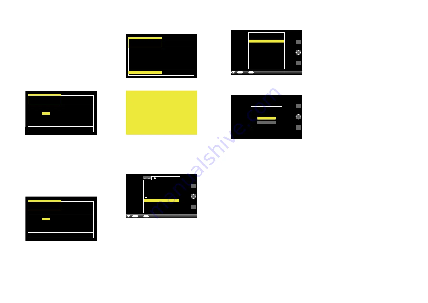
Fig. 2-1-1

Factory

Setting

RTC Test

Software Ver. X. XX. X. XX

Check Sum: XXXXXXXX

Restore all Setting

Format Internal Memory

Model:

D95

U2

CED
E33
KR2
AR2

CEP

E32

CN9
BR4

CA2
CEU
AU3
TW6
E35

CEK

E37
JE3

HK4

Destination:

J1

Fig. 2-1-2

Software Ver. X. XX. X. XX

Check Sum: XXXXXXXX

Restore all Setting

Format Internal Memory

Factory

Setting

RTC Test

Model:

D95

U2

CED
E33
KR2
AR2

CEP

E32

CN9
BR4

CA2
CEU
AU3
TW6

E35

CEK

E37
JE3

HK4

Destination:

J1

Fig. 2-1-3

Software Ver. X. XX. X. XX

Check Sum: XXXXXXXX

Restore all Setting

Format Internal Memory

Factory

Setting

RTC Test

Model:

D95

U2

CED
E33
KR2
AR2

CEP

E32

CN9
BR4

CA2
CEU
AU3
TW6
E35

CEK

E37
JE3

HK4

Destination:

J1

Fig. 2-1-4

Fig. 2-1-5

Settings

Slideshow Settings
Auto Power ON/OFF
Date/time Settings
General Settings
System Information


Language Setting

Initialize

ENTER

BACK

Select

End

/

A

MENU

BACK

ENTER

Fig. 2-1-

6

ENTER

BACK

Select

Return

/

MENU

BACK

ENTER

Initialize

Format internal memory

Initialize settings

All settings will be
returned to factory default.

Yes

MENU

BACK

ENTER

Fig. 2-1-

7

No

Set the destination when the MAIN PWB ASSY SERVICE was replaced.

2-1.  HOW  TO  CHANGE  THE  DESTINATION

Procedure

1.  Plug the AC adapter attached to the set into the DC IN 5V terminal 

on the rear panel of the set and insert the power cord into the socket. 

Press  the 

(on/standby)  button  to  turn  off  the  power  once.

(The power switch LED on the set changes from green to red.)

2.  With the [VIEW MODE] button and [MENU] button pressed, turn 

on  the 

(on/standby)  button,  and  when  the  default  setting

screen (Fig. 2-1-1) appears, release the [VIEW MODE] button and 

[MENU] button.

3.  Check  that  the  model  name  displayed  on  the  side  of  “Model” 

name meets the following: 

D95:  DPF-D95

Note: 

Using [

B

] [

b

] buttons, move a yellow frame to the model 

name to be set.

4.  Red characters of “Destination” show default setting of this set. 

(Fig.  2-1-1  shows  that  the  destination  has  been  set  to  U2) 

Using  [

V

]  [

v

]  [

b

]  [

B

]  buttons,  move  a  yellow  frame  to  the

destination to be set. (Fig. 2-1-1 shows that J1 has been selected as 

destination.)

5.  Press the [ENTER] button, and the characters will change to red, 

indicating that the selected destination was set. (Fig. 2-1-2) 

2-2.  CONFIRMATION OF DESTINATION

6.  With  a  yellow  frame  moved  to  “Restore  all  setting”,  press  the 

[ENTER] button. (Fig. 2-1-3)

7.  The screen becomes yellow and the setting is complete.

8.  With yellow screen displayed, unplug the AC adapter from the DC IN 

5V terminal.

9.  Plug the AC adapter into the DC IN 5V terminal and turn on the 

power.

10.  Press the [MENU] button to display the Settings menu, and select 

“Initialize” to execute. (Fig. 2-1-5)

11.  Select “Reset” of “Initialize” to execute. (Fig. 2-1-6)

12.  Select  “Yes”  to  execute,  and  “Complete”  will  be  displayed, 

indicating that all the default settings have completed.   

(Fig. 2-1-7)

1.  Press the [MENU] button to display the menu, and if the language 

you selected is set, the setting has completed.

– ENGLISH –

Summary of Contents for S-FRAME DPF-D95

Page 1: ...tory Official Release 2010 03 1 0 Sony EMCS Co 985278511 pdf 2010C2900 1 2010 3 Published by Tokai TEC Ver 1 0 2010 03 DIGITAL PHOTO FRAME 9 852 785 11 DPF D95 RMT DPF5 US Model Canadian Model E Model Australian Model Chinese Model Korea Model Argentine Model Brazilian Model Japanese Model ...

Page 2: ...ory capacity 4 256 MB Approx 500 images 5 can be saved Power requirements DC IN jack DC 5V Power consumption Operating temperature 5 C to 35 C 41 F to 95 F Model in operation mode including the AC adaptor at the maximum load 6 6 W normal mode 6 4 W The definition of the normal mode is a status which allows the performance of a slideshow using images stored in the internal memory with the default s...

Page 3: ...電圧など安全上の特性を持った ものとなっています 従って交換部品は 使用されていた ものと同じ特性の部品を使用して下さい 特に回路図 部 品表に0印で指定されている安全上重要な部品は必ず指定 のものをご使用下さい 3 部品の取付けや配線の引きまわしはもとどおりに 安全上 チューブやテープなどの絶縁材料を使用したり プリント基板から浮かして取付けた部品があります また 内部配線は引きまわしやクランパによって発熱部品や高圧 部品に接近しないよう配慮されていますので これらは必 ずもとどおりにして下さい 4 サービス後は安全点検を サービスのために取外したネジ 部品 配線がもとどおり になっているか またサービスした個所の周辺を劣化させ てしまったところがないかなどを点検し 安全性が確保さ れていることを確認して下さい 5 チップ部品交換時の注意 取外した部品は再使用しないで下さい タンタルコン...

Page 4: ...持するために 重要な部品です 従って交換時は 必ず指定の部品を使用 してください 1 1 OVERALL SECTION Abbreviation AR Argentine model AUS Australian model BR Brazilian model CH Chinese model CND Canadian model J Japanese model KR Korea model TW Taiwan model Ref No Part No Description Ref No Part No Description 1 A 1774 136 A FRONT COVER SERVICE 2 A 1776 981 A LCD ASSY SERVICE 3 3 080 206 21 SCREW TAPPING P2 4 4 176 426 01 STAND 5 A 1774 ...

Page 5: ... Frame Handbook 4 174 748 61 SIMPLIFIED CHINESE CH Digital Photo Frame Handbook 4 174 747 81 RUSSIAN 4 174 747 91 UKRAINIAN 4 174 748 11 ARABIC 4 174 748 21 PERSIAN 4 174 748 31 KOREAN 4 174 748 41 SIMPLIFIED CHINESE 4 174 748 51 TRADITIONAL CHINESE CD ROM 4 176 557 01 EXCEPT CH The CD ROM supplied contains all of language version of the Instruction Manual in pdf Digital Photo Frame Handbook pdf f...

Page 6: ... turn off the power once The power switch LED on the set changes from green to red 2 With the VIEW MODE button and MENU button pressed turn on the 1 on standby button and when the default setting screen Fig 2 1 1 appears release the VIEW MODE button and MENU button 3 Check that the model name displayed on the side of Model name meets the following D95 DPF D95 Note Using B b buttons move a yellow f...

Page 7: ...荷時の設定に戻 しますか はい いいえ メニュー 戻る 設定 1 Destination の赤文字がこのセットのデフォルト設定にな ります 図2 1 1は U2仕向け設定になっている状態 黄色枠を設定したい仕向けに V v B b ボタンで移動さ せます 図2 1 1は J1仕向け選択状態 MAIN PWB ASSY SERVICEを交換した場合は 仕向け設定を行っ てください 2 1 仕向け設定変更方法 手順 2 本機に付属のACアダプタのプラグを本機背面のDC IN 5V端子につなぎ電源コードをコンセントに差し込む 1 電源 ボタンを押して一旦電源をOFFにします 本体 電源スイッチのLEDを緑色から赤色にする 3 ビューモード ボタンと メニュー ボタンを押した状態で 1 電源 ボタンをONにして デフォルト設定画面 図2 1 1 が表示されたら ビューモード ボタンと メニュー ボ...

Reviews: