


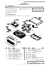


5-3
5-2. Mechanical Adjustment
Note : Refer to the Mechanical Manual for the adjustment and confirmation of Ass’y deck.
5-2-1. The number and position of test point
Test point :
TP601 (Control Pulse)
TP602 (H’D S/W -Trigger)
TP301 (Envelope)
TP302 (Audio output)
TP303 (Video output)
Fig. 5-3 Location of Test point (Main PCB-Top View)
AUDIO OUTPUT
HEAD SWITCHING
ENVELOPE
5-2-2. ACE Head Position (X-Point) Adjustment
(See the 5-2-1(d) ACE Head Position (X-Point) Adjustment
on page 5-2 of the Mechanical Manual)
1) Playback the alignment tape (Color bar).
2) Press the “SW718” button on Main PCB to set the
adjustment mode. (See Fig. 5-2)
3) Press the “5” button of remote control then adjust-
ment is operated automatically. (See Fig. 5-1)
4) Connect the CH-1 probe to TP301 (Envelope) the
CH-2 probe to TP602 (H’D switching pulse) and
then trigger to CH-1.
5) Insert the (-) driver into the X-Point adjustment
hole and adjust it so that envelope waveform is
maximum.
6) Turn the Power off.
www. xiaoyu163. com
QQ 376315150
9
9
2
8
9
4
2
9
8
TEL 13942296513
9
9
2
8
9
4
2
9
8
0
5
1
5
1
3
6
7
3
Q
Q
TEL 13942296513 QQ 376315150 892498299
TEL 13942296513 QQ 376315150 892498299