


Conn
ec
tio
n
s
a
nd
Op
er
at
ions
Turning on the Power
13
GB
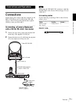
Connecting a Video Switcher
Use a commercially available contact-control type video
switcher to switch between the multiple camera signals
to be output.
For connection with a video switcher, refer to the
Operating Instructions of the switcher.
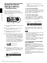
Turning on the Power
1
Connect the camera to an AC outlet.
The power of the camera is turned on and the
POWER lamp lights.
The camera will automatically pan and tilt and be
reset to the position stored in POSITION 1 (Pan/tilt
reset action).
2
Press the ON/OFF switch on this unit to turn it on.
The CAMERA button representing the camera
whose power was turned off last lights. (CAMERA
1 button lights by default.)
3
Turn on the peripheral devices.
Notes
• Be sure to turn on the power of the camera before the
power of this unit. Otherwise, the unit cannot
recognize the connected camera.
• Do not touch the joystick when turning on the power
of the unit. Doing so may affect the confirmation of
the origin.
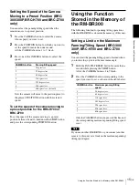
To turn on/off the camera using this unit
As long as the camera is connected to an AC outlet, you
can turn the camera on or off with the POWER button on
this unit.
While holding down the POWER button, press the
CAMERA button corresponding to the camera whose
power you want to turn on/off.
When you turn the power off using this unit, the
POWER lamp turns off and the STANDBY lamp lights
on the camera.
MODE
VISCA
1
9
1
9
RS-422
ON/OFF
TALLY/CONTACT
RS-232C
CONTACT(TALLY)
!
TALLY
CONTACT
DC IN 12V
EXT SYNC IN
IR SELECT
75
1 2 3
OFF
ON
IN VISCA RS-232C OUT
!
VISCA RS-422
1 2 3 4 5 6 7 8 9
DC IN
12V
R
VIDEO
S VIDEO
EXT SYNC IN
IR SELECT
75
1 2 3
OFF
ON
IN VISCA RS-232C OUT
!
VISCA RS-422
1 2 3 4 5 6 7 8 9
DC IN
12V
R
VIDEO
S VIDEO
EXT SYNC IN
IR SELECT
75
1 2 3
OFF
ON
IN VISCA RS-232C OUT
!
VISCA RS-422
1 2 3 4 5 6 7 8 9
DC IN
12V
R
VIDEO
S VIDEO
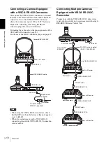
Third to Seventh
camera
to AC outlet
VISCA RS-232C IN
RS-232C cable
VISCA RS-232C OUT
Second camera
VISCA RS-232C IN
RS-232C cable
VISCA RS-232C OUT
First camera
75-ohm
c
oaxial cab
le*
75-ohm
c
oaxial c
a
b
le*
VISCA RS-232C IN
VISCA RS-232C
to contact control
terminal
to
compos
it
e video
input
T
VIDEO
* You can also use an S-video connecting cable to connect the
S VIDEO connector on the camera and the S-video input
connector on the video switcher.
TALLY/CONTACT
75-ohm coax
ial
cab
le*
T
VIDEO
Video switcher (commercially available)
RS-232C cable (supplied)
(SONY: 1-590-879-3X)
Camera
BRC-300/300P
1
1
9
LOCK
MODE
VALUE
RESET
MENU
PRESET
SHIFT
L/R
DIRECTION
PANEL
LIGHT
BLACK
LIGHT
PAN-TILT
RESET
ONE PUSH
AWB
POWER
AUTO
MANUAL
AUTO
ONE PUSH
AF
2
3
4
5
6
7
2
10
STD
REV
3
11
4
POSITION
CAMERA
12
5
13
6
14
7
15
8
16
R
–
+
BRIGHT
B
–
+
FOCUS
NEAR
FAR
1
2
PANEL LIGHT
POWER
CAMERA
RESET


