background image

1-19

79

Set
ting
s and

 Ad
ju

st

m

ent
s

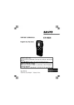
Video Settings (Video)

The “Video” setup allows you to adjust items 
related to the image, such as size and color.
Choose the settings according to the type of TV, 
tuner, or decoder connected to the recorder.

1

Press SYSTEM MENU while the recorder is 
in stop mode.

2

Select “Setup,” and press ENTER.

3

Select “Video,” and press ENTER.

The “Video” setup appears with the following 
options. The default settings are underlined.

TV Type

Selects the aspect ratio of the connected TV (4:3 
standard or wide).

Note

Depending on the disc, “4:3 Letter Box” may be selected 
automatically instead of “4:3 Pan Scan” or vice versa.

HDMI Resolution

Selects the type of video signals output from the 
HDMI OUT jack. When you select 
“Auto”(default), the recorder outputs video 
signals of the highest resolution acceptable for 
your TV. If the picture is not clear, unnatural or 
not to your satisfaction, try another option that 
suits the disc and your TV/projector, etc. For 
details, refer also to the instruction manual 
supplied with the TV/projector, etc.
The setting is effective only when you connect an 
HDMI equipped TV to the HDMI OUT jack.

Video (HDMI)

Selects the type of output from the HDMI OUT 
jack.
The setting is effective only when you connect an 
HDMI equipped TV to the HDMI OUT jack.

16:9

Select this when connecting to a 
wide-screen TV or TV with a 
wide mode function.

4:3 Letter 
Box

Select this when connecting to a 
4:3 screen TV. Displays a wide 
picture with bands on the upper 
and lower portions of the screen.

4:3 Pan 
Scan

Select this when connecting to a 
4:3 screen TV. Automatically 
displays a wide picture on the 
entire screen and cuts off the 
portions that do not fit.

Video

10:10 AM

TV Type

HDMI Resolution

Video (HDMI)

Black Level

Picture Control

Progressive

:  16:9

:  Auto

:  Y Cb Cr

:  On

:  Standard

:  Off

Setup

Disc Setting

Edit

Title List

Timer

DV/D8 Dubbing

Auto

Normally, select this.

1920×1080i

Sends 1920×1080i video signals.

1280×720P

Sends 1280×720p video signals.

720×480P

Sends 720×480p video signals.

Y  Cb  Cr

Selects this when connecting to 
an HDMI device.

RGB

Gives brighter colors and deeper 
black. Select this if colors are 
weak.

16:9

4:3 Letter Box

4:3 Pan Scan

,

continued

80

Black Level

Selects the black level (setup level) for the video 
signals output from the LINE OUT jacks 
(page 21).
This setting is not effective when the 
“PROGRESSIVE” indicator lights up on the front 
panel display and the recorder outputs progressive 
signals.

Picture Control

Selects the picture control for the video signals 
output from the LINE OUT jacks (page 21).
You can adjust the video signal of DVD or 
VIDEO CD (with PBC function off) from the 
recorder to obtain the picture quality you want. 
Select the setting that best suits the program you 
are watching.

z

Hint

When you watch a movie, “Cinema 1” or “Cinema 2” is 
recommended.

Progressive

If your TV accepts progressive (480p) format 
signals, you will enjoy accurate color reproduction 
and high quality image.
Connect your TV to the COMPONENT VIDEO 
OUT jacks (page 23).

Notes

• If you select progressive signals when you connect the 

recorder to a TV that cannot accept the signal in 
progressive format, the image quality will deteriorate. 
In this case, set “Progressive” to “Off.” Or, while the 
recorder is in stop mode, and then hold down 

X

PAUSE on the recorder for five seconds or more.

• When  you  connect your TV using an HDMI cable, the 

“Progressive” setting is set to “On.”

On

Raises the standard black level. 
Select this when the picture 
appears too dark.

Off

Sets the black level of the output 
signal to the standard level.

Dynamic 1

Produces a bold dynamic picture 
by increasing the picture contrast 
and the color.

Dynamic 2

Produces a more dynamic picture 
than “Dynamic 1” by further 
increasing the picture contrast 
and the color.

Standard

Displays a standard picture 
(function turned off).

Cinema 1

White colors become brighter 
and black colors become richer, 
and the color contrast is 
increased.

Cinema 2

Enhances details in dark areas by 
increasing the black level.

Personal

Adjusts “Contrast,” “Brightness,” 
“Color,” and “Hue” using 

M

/

m

/

<

/

,

.

On

Set the recorder to output 
progressive signals.

Off

Outputs video signals in interlace 
format.

81

Set
ting
s and

 Ad
ju

st

m

ent
s

Audio Settings (Audio)

The “Audio” setup allows you to adjust the sound 
according to the playback and connection 
conditions.

1

Press SYSTEM MENU while the recorder is 
in stop mode.

2

Select “Setup,” and press ENTER.

3

Select “Audio,” and press ENTER.

The “Audio” setup appears with the following 
options. The default settings are underlined.

Tuner Audio

Selects the sound to be recorded.

Note

If no SAP sound is received, the main sound is recorded 
regardless of the setting.

Digital Out

The following setup items switch the method of 
outputting audio signals when you connect a 
component such as an amplifier (receiver) with a 
digital input jack to the DIGITAL AUDIO OUT 
(OPTICAL or COAXIAL)/HDMI OUT jack.
For connection details, see “Connecting to Your 
AV Amplifier (Receiver)” on page 24.
Press ENTER, and select “Dolby Digital” or 
“DTS.”

If you connect a component that does not accept 
the selected audio signal, a loud noise (or no 
sound) will come out from the speakers, and may 
affect your ears or cause speaker damage.

 Dolby Digital

Selects the type of Dolby Digital signal.

Notes

• If  the HDMI OUT jack is connected to equipment not 

compatible with Dolby Digital signals, D-PCM signals 
will be automatically output, even when “Dolby 
Digital” is selected.

• The HDMI OUT jack cannot output Dolby Digital 

signals for digital broadcasts. To hear Dolby Digital, 
use the DIGITAL AUDIO OUT jacks.

 DTS (DVD VIDEOs only)

Selects whether or not to output DTS signals.

Main

Records only the main 
sound.

SAP

Records only the SAP 
(Second Audio Program) 
sound.

Audio

10:10 AM

Setup

Disc Setting

Edit

Title List

Timer

Tuner Audio

Digital Out

Downmix

Audio DRC

Audio (HDMI)

Scan Audio

Surround

DV/D8 Audio Input

Line Audio Input

:  Main

:  Dolby Surround

:  Standard

:  Auto

:  On

:  Off

:  Stereo 1

:  Stereo

DV/D8 Dubbing

D-PCM

Select this when the recorder 
is connected to an audio 
component lacking a built-in 
Dolby Digital decoder. You 
can select whether the 
signals conform to Dolby 
Surround or not by making 
adjustments to the 
“Downmix” item in “Audio” 
setup (page 82).

Dolby 
Digital

Select this when the recorder 
is connected to an audio 
component with a built-in 
Dolby Digital decoder.

On

Select this when the recorder 
is connected to an audio 
component with a built-in 
DTS decoder.

Off

Select this when the recorder 
is connected to an audio 
component without a built-in 
DTS decoder.

10:10 AM

Dolby Digital

DTS

Digital Out

:  4:3 Letter Box

  On

Setup

Disc Setting

Edit

Title List

Timer

DV/D8 Dubbing

D-PCM

Dolby Digital

,

continued

82

Note

If the HDMI OUT jack is connected to equipment not 
compatible with DTS signals, no signal will be output, 
regardless of the “DTS” setting.

Downmix (DVDs only)

Switches the method for mixing down to two 
channels when you play a DVD which has rear 
sound elements (channels) or is recorded in Dolby 
Digital format. For details on the rear signal 
components, see “A Connecting to audio L/R 
jacks” on page 25. This function affects the output 
of the following jacks:
– LINE OUT (AUDIO L/R) jacks
– AUDIO OUT L/R jacks
– DIGITAL AUDIO OUT (OPTICAL or 

COAXIAL)/HDMI OUT jack when “Dolby 
Digital” is set to “D-PCM” (page 81).

To enjoy the surround effect of Dolby Digital, turn 
off the surround settings of this recorder (page 
102).

Audio DRC (Dynamic Range Control) (DVDs 
only)

Makes the sound clear when the volume is turned 
down when playing a DVD that conforms to 
“Audio DRC.” This affects the output from the 
following jacks:
– LINE OUT (AUDIO L/R) jacks
– AUDIO OUT L/R jacks
– DIGITAL AUDIO OUT (OPTICAL or 

COAXIAL)/HDMI OUT jack only when 
“Dolby Digital” is set to “D-PCM” (page 81).

Audio (HDMI) (DVD VIDEOs only)

Select the output method from the HDMI OUT 
jack.

Note

Dolby Digital signals on digital broadcasts will be 
converted to PCM signals.

Scan Audio (DVDs only)

Note

Sound will be interrupted during Scan Audio.

Surround

Turns on the surround function to create virtual 
rear speakers from a stereo TV or two front 
speakers (page 25).

Notes

• When the playback signal does not contain a signal for 

the surround speakers, the surround effects will be 
difficult to hear.

• When you select one of the surround modes, turn off 

the surround settings of the connected TV or amplifier 
(receiver).

Dolby 
Surround

Normally select this 
position.
Multi-channel audio signals 
are output to two channels 
for enjoying surround 
sounds.

Normal

Multi-channel audio signals 
are downmixed to two 
channels for use with your 
stereo.

Standard

Normally select this 
position.

TV Mode

Makes low sounds clear 
even if you turn the volume 
down.

Wide 
Range

Gives you the feeling of 
being at a live performance.

Auto

Normally, select this. 
Outputs audio signals 
according to the “Dolby 
Digital” setting.

PCM

Converts Dolby Digital to 
PCM.

On

Outputs audio signals during 
FF1 fast-forward of a DVD 
disc with Dolby Digital 
soundtracks.

Off

No sound is output during 
FF1 fast-forward.

Off

No surround effect.

Surround1

Creates one set of virtual 
surround speakers.

Surround2

Creates two sets of virtual 
surround speakers.

Surround3

Creates three sets of virtual 
surround speakers.

www. xiaoyu163. com

QQ 376315150

9

9

2

8

9

4

2

9

8

TEL 13942296513

9

9

2

8

9

4

2

9

8

0

5

1

5

1

3

6

7

3

Q

Q

TEL  13942296513  QQ  376315150  892498299 

TEL  13942296513  QQ  376315150  892498299 

http://www.xiaoyu163.com

http://www.xiaoyu163.com

Summary of Contents for RDRGXD455 - DVD Recorder With TV Tuner

Page 1: ... Input impedance more than 47 kilohms LINE 2 IN S VIDEO 4 pin mini DIN jack Y 1 0 Vp p unbalanced sync negative C 0 286 Vp p load impedance 75 ohms DV IN 4 pin jack i LINK S100 LINE OUT VIDEO OUT phono jack 1 Output signal 1 Vp p 75 ohms unbalanced sync negative AUDIO OUT phono jacks 2 Standard output 327 mVrms Load impedance 47 kilohms Output impedance less than 10 kilohms DIGITAL AUDIO OUT OPTIC...

Page 2: ... d Approx 430 70 287 mm Approx 17 2 7 8 113 8 inches Mass Approx 3 2 kg Approx 7 1 lbs Supplied accessories Remote commander remote 1 Size AA R6 batteries 2 Antenna cable 1 Audio video cord 1 Design and specifications are subject to change without notice www xiaoyu163 com QQ376315150 9 9 2 8 9 4 2 9 8 TEL 13942296513 9 9 2 8 9 4 2 9 8 0 5 1 5 1 3 6 7 3 Q Q TEL 13942296513 QQ 376315150 892498299 TE...

Page 3: ... and bridges 2 Check the interboard wiring to ensure that no wires are pinched or contact high wattage resistors 3 Look for unauthorized replacement parts particularly transistors that were installed during a previous repair Point them out to the customer and recommend their replacement 4 Look for parts which though functioning show obvious signs of deterioration Point them out to the customer and...

Page 4: ...D Main PCB 4 3 4 2 Front Main PCB 4 7 4 3 Function Timer PCB 4 11 5 Schematic Diagrams 5 1 S M P S Front Main PCB 5 3 5 2 Power Front Main PCB 5 5 5 3 Logic Front Main PCB 5 7 5 4 ATSC TM Connector Front Main PCB 5 9 5 5 MPEG Decoder DVD Main PCB 5 11 5 6 A V Decoder DVD Main PCB 5 13 5 7 In Out DVD Main PCB 5 15 5 8 DV HDMI DVD Main PCB 5 17 5 9 Front Panel Function Timer PCB 5 19 5 10 Function J...

Page 5: ...n the two prongs of the plug 2 Turn on the power switch of the instrument 3 Measure the resistance with an ohmmeter between the jumpered AC plug and all exposed metallic cabinet parts on the instrument such as screwheads antenna control shafts handle brackets etc When an exposed metallic part has a return path to the chassis the reading should be between 1 and 5 2 megohm When there is no return pa...

Page 6: ...tified by shading an or a on schematics and parts lists Use of a substitute replacement that does not have the same safety characteristics as the recommended replacement part might create shock fire and or other hazards Product safety is under review continuously and new instructions are issued whenever appropriate www xiaoyu163 com QQ376315150 9 9 2 8 9 4 2 9 8 TEL 13942296513 9 9 2 8 9 4 2 9 8 0...

Page 7: ...nted or indicated service precautions and service materials 3 The components used in the unit have a specified flame resistance and dielectric strength When replacing components use components which have the same ratings Components identified by shading by or by in the circuit diagram are important for safety or for the characteristics of the unit Always replace them with the exact replacement com...

Page 8: ... removal devices Some solder removal devices not classified as anti static can generate electrical charges sufficient to damage ESD devices 5 Do not use freon propelled chemicals These can generate electrical charges sufficient to damage ESD devices 6 Do not remove a replacement ESD device from its protective package until immediately before your are ready to install it Most replacement ESD device...

Page 9: ...et Be careful not to let your clothes or any other static sources to touch the unit Be sure to put on a wrist strap grounded to the sheet Be sure to lay a conductive sheet made of copper etc Which is grounded to the table Fig 3 6 Short the short terminal on the PCB which is inside the Pick UpASS Y before replacing the Pick Up The short terminal is shorted when the Pick Up Ass y is being lifted or ...

Page 10: ...mes the 1 button on the remote commander For an entering method of Adjustment mode see 6 1 The tray will automatically open and the version information will be displayed on the TV screen 2 Turn the power off www xiaoyu163 com QQ376315150 9 9 2 8 9 4 2 9 8 TEL 13942296513 9 9 2 8 9 4 2 9 8 0 5 1 5 1 3 6 7 3 Q Q TEL 13942296513 QQ 376315150 892498299 TEL 13942296513 QQ 376315150 892498299 http www x...

Page 11: ...deo camera to the DV IN jack and press the ONE TOUCH DUBBING button to dub a DV D8 format tape over to a disc page 71 Playing JPEG image files or MP3 audio files You can enjoy viewing JPEG images on your TV screen First take pictures with a digital camera and save them in JPEG format to a DATA CD CD RW CD R or DATA DVD DVD RW DVD RW DVD R DVD R on a PC Then play the disc on this recorder page 43 Y...

Page 12: ...Compatibility with other DVD players finalizing DVD RW Automatically formatted Playable on DVD RW compatible players automatically finalized DVD RW VR mode Format in VR mode 2 page 48 Playable only on VR mode compatible players finalization unnecessary page 69 Video mode Format in Video mode 2 page 48 Playable on most DVD players finalization necessary page 69 DVD R Automatically formatted Playabl...

Page 13: ...sc or the characteristics of the recording device and authoring software The disc will not play if it has not been correctly finalized For more information see the operating instructions for the recording device Notes You cannot mix VR mode and Video mode on the same DVD RW or DVD R To change the DVD RW s format reformat the disc page 68 Note that a disc s contents will be erased after reformattin...

Page 14: ... the S VIDEO OUT and yellow LINE OUT VIDEO jacks at the same time Do not connect your TV s audio output jacks to the LINE IN AUDIO L R jacks at the same time This will cause unwanted noise to come from your TV s speakers L R VIDEO AUDIO LINE OUT VHF UHF VIDEO Y L PB R PR AUDIO LINE 1 IN AUDIO OUT SVIDEO OUT COMPONENT VIDEO OUT DIGITAL AUDIO OUT OPTICAL COAXIAL HDMI OUT IN OUT L R VIDEO AUDIO LINE ...

Page 15: ...r location see the operating instructions supplied with the connected components Notes After you have completed the connection make the appropriate settings under Audio Connection Setup in Easy Setup page 29 Otherwise no sound or a loud noise will come from your speakers With a coaxial or optical digital connection you cannot use the virtual surround effects of this recorder When outputting from t...

Page 16: ...ntrol Caption Service Caption Setting Front Display Command Mode Factory Setting 16 9 Off Auto DVD 3 DV D8 Dubbing DVD 1 DVD 2 DVD 3 29 Hookups and Settings B While holding down ENTER enter the command mode code number using the number buttons C Hold down both the number buttons and ENTER at the same time for more than three seconds To return to the previous display Press O RETURN To check the com...

Page 17: ...VD recorder to LINE 2 IN Signal flow 33 Hookups and Settings Connecting to the LINE 1 IN jacks You can connect a VCR or similar device z Hints When the connected equipment outputs only monaural sound connect an audio cord to the white LINE IN AUDIO L mono jack To record from connected equipment select an input source LINE1 or LINE2 to match the jack you connected to page 55 Notes Do not connect mo...

Page 18: ...cts the audio source Selects stereo or monaural audio tracks SUBTITLE Selects a subtitle language when pressed repeatedly REPLAY ADVANCE Replays or briefly fast forwards a scene when pressed during playback Goes to the previous or next frame when pressed during pause mode PREV NEXT Goes to the beginning of the current or next title chapter scene track and starts playback when pressed during playba...

Page 19: ...ected D Clock RW R RWVR RWVideo RAM RVR RVideo 1 1 2 2 3 3 4 4 5 5 6 6 7 7 8 8 0 0 9 9 TOP MENU M m ENTER MENU TITLE LIST ORIGINAL PLAYLIST 10 10 AM 01 01 29 03 02 00 31 23 03 01 59 00 04 00 58 56 08 00 PM T No Title Length Edit Title List Original 1 4 D11 1 D22 2 Ch 23 Ch 66 D11 1 May 02 2007 1 2 3 4 3 41 Playback 3 Select the title and press ENTER The sub menu appears 4 Select Play and press ENT...

Page 20: ...3 The slide show is played repeatedly until MP3 playback stops 10 10 AM Photo Music Press ENTER Mix Music menu for this disc 45 Playback About MP3 audio tracks and JPEG image files MP3 is audio compression technology that satisfies the ISO IEC MPEG regulations JPEG is image compression technology You can play back DATA CDs CD ROMs CD Rs CD RWs or DATA DVDs DVD ROMs DVD RWs DVD RWs DVD Rs DVD Rs re...

Page 21: ...e 68 Notes You cannot mix VR mode and Video mode on the same DVD RW or DVD R You can change the recording format on DVD RWs by reformatting page 68 You cannot change the recording format on used DVD Rs The recorder records on new DVD Rs in Video mode unless you first format the discs in VR mode Copy control signals Recordable discs Copy Free Copy Once Ver 1 1 Ver 1 2 with CPRM Ver 2 0 Ver 2 1 with...

Page 22: ... the recorder turned on The recorder does not record programs with Copy Never signals Such recordings stop after a few seconds Digital closed captions cannot be recorded page 35 For audio settings Stream 1 is usually recorded page 35 When you set the Digital Rating a program with a digital rating beyond your limit setting cannot be recorded correctly page 85 7 00 8 00 9 00 10 00 7 00 8 00 9 00 10 ...

Page 23: ...on against erasure DVD RWs only page 58 Erasing a section of a title A B Erase DVD RWs only page 59 Dividing a title DVD RWs only page 60 Notes Once the disc is finalized you cannot edit or record on the disc except for DVD RWs If a message appears and indicates that the disc s control information is full erase unnecessary titles Edit options for DVD RWs VR mode DVD Rs VR mode You can enjoy advanc...

Page 24: ... title and press ENTER The sub menu appears 3 Select Divide Title and press ENTER The display for setting the dividing point appears Point is selected A B Erase 10 10 AM Title No 01 End 00 00 00 Start 00 00 00 Start End Erase Finish 00 00 07 T Title No 01 May 02 2007 08 00 PM A B Erase 10 10 AM Title No 01 End 00 00 00 Start 00 00 10 Start End Erase Finish 00 00 10 T Title No 01 May 02 2007 08 00 ...

Page 25: ... edit Playlist titles on a finalized disc When you want to edit or record on the DVD RW VR mode again unfinalize the disc page 69 Combining two titles into one Combine Titles You can select a Playlist title and combine it with another Playlist title 1 Follow steps 1 to 4 of Editing a Playlist page 64 to select a Playlist title The sub menu appears 2 Select Combine Titles and press ENTER The next t...

Page 26: ...ting you can change the recording format on DVD RWs or record again on DVD RWs Video mode that have been finalized Notes You can label a disc using up to 32 characters however the name may not display on other DVD equipment You cannot label an unused DVD R Video mode disc Label the disc after you first record on it You cannot mix VR mode and Video mode on the same DVD RW or DVD R You cannot change...

Page 27: ...r DV D8 Dubbing Audio 10 10 AM Setup Disc Setting Edit Title List Timer Tuner Audio Digital Out Downmix Audio DRC Audio HDMI Scan Audio Surround DV D8 Audio Input Line Audio Input Main Dolby Surround Standard Auto On Off Stereo 1 Stereo DV D8 Dubbing 73 DV D8 Dubbing DV D8 t DVD 9 Select DV D8 Audio Input and press ENTER Stereo 1 Records original sound only Normally select this when dubbing a DV f...

Page 28: ... channels manually If some channels cannot be set using the Auto Preset or Easy Setup function you can set them manually Digital channels are only scanned when Auto Preset is set page 76 Erases any unnecessary digital or analog channels manually 1 Select Antenna Cable and press ENTER Antenna Presets VHF and UHF channels Cable Presets cable TV channels 2 Select an option and press ENTER 3 Select Ma...

Page 29: ...ed the main sound is recorded regardless of the setting Digital Out The following setup items switch the method of outputting audio signals when you connect a component such as an amplifier receiver with a digital input jack to the DIGITAL AUDIO OUT OPTICAL or COAXIAL HDMI OUT jack For connection details see Connecting to Your AV Amplifier Receiver on page 24 Press ENTER and select Dolby Digital o...

Page 30: ...hen you have already registered a password the display for entering the password appears Enter a 4 digit password using the number buttons 2 The Parental menu appears z Hint If you enter a wrong number press or CLEAR and reenter Digital Rating You can lock certain unsuitable channels to prevent children accessing them or set a rating so that any program classed above that rating by the broadcaster...

Page 31: ...t 480p signals the image may be affected when you set the recorder to progressive format In this case set Progressive to Off in Video setup page 80 There is no picture or the picture noise appears when connected to the DV IN jack Try the following 1Turn the recorder off and on again 2Turn the connected equipment off and on again 3Disconnect and then connect the i LINK cable again There is no pictu...

Page 32: ...recording The disc has 99 or more titles which prevents further recording The disc is protected page 68 Contents previously recorded were erased Data that has been recorded on a DVD with a PC will be erased from the disc when the disc is inserted Display Menus or displays do not appear on the screen While the recorder is reading disc information the System Menu OPTIONS menu or information display ...

Page 33: ...e the instruction manuals for the equipment to be connected Required i LINK cable Use the Sony i LINK 4 pin to 4 pin cable during DV D8 dubbing i LINK and are trademarks 97 Additional Information Guide to Parts and Controls For more information see the pages in parentheses Front panel Buttons on the recorder have the same function as the buttons on the remote if they have the same or similar names...

Page 34: ... of an image as a single field and is the standard method for displaying images on television The even number field shows the even numbered lines of an image and the odd numbered field shows the odd numbered lines of an image Original page 57 Titles actually recorded on a DVD RW VR mode or DVD R VR mode Erasing original titles frees up disc space on DVD RWs Playlist page 57 Playback information cr...

Page 35: ...e 46 Remote 26 98 REPLAY 37 Resetting 88 Resume Play 39 Rotate 44 S SAP Second Audio Program 48 Satellite receiver 18 Scan Audio 39 82 Searching for Chapter 41 for Title 41 for Track 41 Time Search 41 Settings 75 Setup Display 75 Slide show 44 Stereo programs 48 STOP 36 49 Sub menu 11 SUBTITLE 37 Subtitle 84 Surround 82 SYNCHRO REC 53 System Menu 10 T Time Zone 78 TIMER 51 Timer List 54 Timer reco...

Page 36: ...oyu163 com QQ376315150 9 9 2 8 9 4 2 9 8 TEL 13942296513 9 9 2 8 9 4 2 9 8 0 5 1 5 1 3 6 7 3 Q Q TEL 13942296513 QQ 376315150 892498299 TEL 13942296513 QQ 376315150 892498299 http www xiaoyu163 com http www xiaoyu163 com ...

Page 37: ...g 2 1 Cabinet Top Removal 1 RELEASE 2 HOOKS Top View 2 RELEASE 3 HOOKS Bottom View 3 FRONT PANEL Fig 2 2 Ass y Front Panel Removal www xiaoyu163 com QQ376315150 9 9 2 8 9 4 2 9 8 TEL 13942296513 9 9 2 8 9 4 2 9 8 0 5 1 5 1 3 6 7 3 Q Q TEL 13942296513 QQ 376315150 892498299 TEL 13942296513 QQ 376315150 892498299 http www xiaoyu163 com http www xiaoyu163 com ...

Page 38: ...EWS qs REMOVE 3 SCREWS qd ASSY PWB MAIN DVD 4 REMOVE 2 SCREWS 5 FAN DC 8 REMOVE CONNECTOR qa REMOVE 5 SCREWS 2 SHIELD LOADER www xiaoyu163 com QQ376315150 9 9 2 8 9 4 2 9 8 TEL 13942296513 9 9 2 8 9 4 2 9 8 0 5 1 5 1 3 6 7 3 Q Q TEL 13942296513 QQ 376315150 892498299 TEL 13942296513 QQ 376315150 892498299 http www xiaoyu163 com http www xiaoyu163 com ...

Page 39: ...SY PWB MAIN DVD Fig 2 4 Circuit Board Locations www xiaoyu163 com QQ376315150 9 9 2 8 9 4 2 9 8 TEL 13942296513 9 9 2 8 9 4 2 9 8 0 5 1 5 1 3 6 7 3 Q Q TEL 13942296513 QQ 376315150 892498299 TEL 13942296513 QQ 376315150 892498299 http www xiaoyu163 com http www xiaoyu163 com ...

Page 40: ...yu163 com QQ376315150 9 9 2 8 9 4 2 9 8 TEL 13942296513 9 9 2 8 9 4 2 9 8 0 5 1 5 1 3 6 7 3 Q Q TEL 13942296513 QQ 376315150 892498299 TEL 13942296513 QQ 376315150 892498299 http www xiaoyu163 com http www xiaoyu163 com ...

Page 41: ...INE2 IN REAR SUPER IN SUPER OUT COAXLAL OPTICAL IEC958 DIGITAL AUDIO OUT DV IN VIDEO L L R R Y Pb Pr 2 RF SIF CVBS TM BLOCK NTSC ATSC TS TVP9005 BT656 DATA A D SW 74VHC541 12S DAC Audio LR ATSC_V_I Notes Special key has been written in the IC103 CPRM key and therefore the IC103 cannot be replaced If this IC is faulty replace the board entirely w w w x i a o y u 1 6 3 c o m Q Q 3 7 6 3 1 5 1 5 0 9 ...

Page 42: ... o m Q Q 3 7 6 3 1 5 1 5 0 9 9 2 8 9 4 2 9 8 T E L 1 3 9 4 2 2 9 6 5 1 3 9 9 2 8 9 4 2 9 8 0 5 1 5 1 3 6 7 3 Q Q TEL 13942296513 QQ 376315150 892498299 TEL 13942296513 QQ 376315150 892498299 http www xiaoyu163 com http www xiaoyu163 com ...

Page 43: ...er PCB 4 11 RDR GXD455 w w w x i a o y u 1 6 3 c o m Q Q 3 7 6 3 1 5 1 5 0 9 9 2 8 9 4 2 9 8 T E L 1 3 9 4 2 2 9 6 5 1 3 9 9 2 8 9 4 2 9 8 0 5 1 5 1 3 6 7 3 Q Q TEL 13942296513 QQ 376315150 892498299 TEL 13942296513 QQ 376315150 892498299 http www xiaoyu163 com http www xiaoyu163 com ...

Page 44: ...a o y u 1 6 3 c o m Q Q 3 7 6 3 1 5 1 5 0 9 9 2 8 9 4 2 9 8 T E L 1 3 9 4 2 2 9 6 5 1 3 9 9 2 8 9 4 2 9 8 0 5 1 5 1 3 6 7 3 Q Q TEL 13942296513 QQ 376315150 892498299 TEL 13942296513 QQ 376315150 892498299 http www xiaoyu163 com http www xiaoyu163 com ...

Page 45: ...1 6 3 c o m Q Q 3 7 6 3 1 5 1 5 0 9 9 2 8 9 4 2 9 8 T E L 1 3 9 4 2 2 9 6 5 1 3 9 9 2 8 9 4 2 9 8 0 5 1 5 1 3 6 7 3 Q Q TEL 13942296513 QQ 376315150 892498299 TEL 13942296513 QQ 376315150 892498299 http www xiaoyu163 com http www xiaoyu163 com ...

Page 46: ... a o y u 1 6 3 c o m Q Q 3 7 6 3 1 5 1 5 0 9 9 2 8 9 4 2 9 8 T E L 1 3 9 4 2 2 9 6 5 1 3 9 9 2 8 9 4 2 9 8 0 5 1 5 1 3 6 7 3 Q Q TEL 13942296513 QQ 376315150 892498299 TEL 13942296513 QQ 376315150 892498299 http www xiaoyu163 com http www xiaoyu163 com ...

Page 47: ...1 6 3 c o m Q Q 3 7 6 3 1 5 1 5 0 9 9 2 8 9 4 2 9 8 T E L 1 3 9 4 2 2 9 6 5 1 3 9 9 2 8 9 4 2 9 8 0 5 1 5 1 3 6 7 3 Q Q TEL 13942296513 QQ 376315150 892498299 TEL 13942296513 QQ 376315150 892498299 http www xiaoyu163 com http www xiaoyu163 com ...

Page 48: ...E w w w x i a o y u 1 6 3 c o m Q Q 3 7 6 3 1 5 1 5 0 9 9 2 8 9 4 2 9 8 T E L 1 3 9 4 2 2 9 6 5 1 3 9 9 2 8 9 4 2 9 8 0 5 1 5 1 3 6 7 3 Q Q TEL 13942296513 QQ 376315150 892498299 TEL 13942296513 QQ 376315150 892498299 http www xiaoyu163 com http www xiaoyu163 com ...

Page 49: ...rwise noted Special note Most semiconductor devices are electrostatically sensitive and therefore require the special handling techniques described under the electrostatically sensitive ES devices section of this service manual Important safety notices Components identified with the mark 0 have the special characteristics for safety When replacing any of these components Use only the same type w w...

Page 50: ...o y u 1 6 3 c o m Q Q 3 7 6 3 1 5 1 5 0 9 9 2 8 9 4 2 9 8 T E L 1 3 9 4 2 2 9 6 5 1 3 9 9 2 8 9 4 2 9 8 0 5 1 5 1 3 6 7 3 Q Q TEL 13942296513 QQ 376315150 892498299 TEL 13942296513 QQ 376315150 892498299 http www xiaoyu163 com http www xiaoyu163 com ...

Page 51: ... y u 1 6 3 c o m Q Q 3 7 6 3 1 5 1 5 0 9 9 2 8 9 4 2 9 8 T E L 1 3 9 4 2 2 9 6 5 1 3 9 9 2 8 9 4 2 9 8 0 5 1 5 1 3 6 7 3 Q Q TEL 13942296513 QQ 376315150 892498299 TEL 13942296513 QQ 376315150 892498299 http www xiaoyu163 com http www xiaoyu163 com ...

Page 52: ... y u 1 6 3 c o m Q Q 3 7 6 3 1 5 1 5 0 9 9 2 8 9 4 2 9 8 T E L 1 3 9 4 2 2 9 6 5 1 3 9 9 2 8 9 4 2 9 8 0 5 1 5 1 3 6 7 3 Q Q TEL 13942296513 QQ 376315150 892498299 TEL 13942296513 QQ 376315150 892498299 http www xiaoyu163 com http www xiaoyu163 com ...

Page 53: ... i a o y u 1 6 3 c o m Q Q 3 7 6 3 1 5 1 5 0 9 9 2 8 9 4 2 9 8 T E L 1 3 9 4 2 2 9 6 5 1 3 9 9 2 8 9 4 2 9 8 0 5 1 5 1 3 6 7 3 Q Q TEL 13942296513 QQ 376315150 892498299 TEL 13942296513 QQ 376315150 892498299 http www xiaoyu163 com http www xiaoyu163 com ...

Page 54: ...a o y u 1 6 3 c o m Q Q 3 7 6 3 1 5 1 5 0 9 9 2 8 9 4 2 9 8 T E L 1 3 9 4 2 2 9 6 5 1 3 9 9 2 8 9 4 2 9 8 0 5 1 5 1 3 6 7 3 Q Q TEL 13942296513 QQ 376315150 892498299 TEL 13942296513 QQ 376315150 892498299 http www xiaoyu163 com http www xiaoyu163 com ...

Page 55: ...a o y u 1 6 3 c o m Q Q 3 7 6 3 1 5 1 5 0 9 9 2 8 9 4 2 9 8 T E L 1 3 9 4 2 2 9 6 5 1 3 9 9 2 8 9 4 2 9 8 0 5 1 5 1 3 6 7 3 Q Q TEL 13942296513 QQ 376315150 892498299 TEL 13942296513 QQ 376315150 892498299 http www xiaoyu163 com http www xiaoyu163 com ...

Page 56: ... y u 1 6 3 c o m Q Q 3 7 6 3 1 5 1 5 0 9 9 2 8 9 4 2 9 8 T E L 1 3 9 4 2 2 9 6 5 1 3 9 9 2 8 9 4 2 9 8 0 5 1 5 1 3 6 7 3 Q Q TEL 13942296513 QQ 376315150 892498299 TEL 13942296513 QQ 376315150 892498299 http www xiaoyu163 com http www xiaoyu163 com ...

Page 57: ...y u 1 6 3 c o m Q Q 3 7 6 3 1 5 1 5 0 9 9 2 8 9 4 2 9 8 T E L 1 3 9 4 2 2 9 6 5 1 3 9 9 2 8 9 4 2 9 8 0 5 1 5 1 3 6 7 3 Q Q TEL 13942296513 QQ 376315150 892498299 TEL 13942296513 QQ 376315150 892498299 http www xiaoyu163 com http www xiaoyu163 com ...

Page 58: ... y u 1 6 3 c o m Q Q 3 7 6 3 1 5 1 5 0 9 9 2 8 9 4 2 9 8 T E L 1 3 9 4 2 2 9 6 5 1 3 9 9 2 8 9 4 2 9 8 0 5 1 5 1 3 6 7 3 Q Q TEL 13942296513 QQ 376315150 892498299 TEL 13942296513 QQ 376315150 892498299 http www xiaoyu163 com http www xiaoyu163 com ...

Page 59: ...o y u 1 6 3 c o m Q Q 3 7 6 3 1 5 1 5 0 9 9 2 8 9 4 2 9 8 T E L 1 3 9 4 2 2 9 6 5 1 3 9 9 2 8 9 4 2 9 8 0 5 1 5 1 3 6 7 3 Q Q TEL 13942296513 QQ 376315150 892498299 TEL 13942296513 QQ 376315150 892498299 http www xiaoyu163 com http www xiaoyu163 com ...

Page 60: ...x i a o y u 1 6 3 c o m Q Q 3 7 6 3 1 5 1 5 0 9 9 2 8 9 4 2 9 8 T E L 1 3 9 4 2 2 9 6 5 1 3 9 9 2 8 9 4 2 9 8 0 5 1 5 1 3 6 7 3 Q Q TEL 13942296513 QQ 376315150 892498299 TEL 13942296513 QQ 376315150 892498299 http www xiaoyu163 com http www xiaoyu163 com ...

Page 61: ...ck the voltage f RIS02 RIS03 and DIS05 Replace Q1S01 No No Voltage at Collector of Q1S01 No Yes Yes Yes Operation of Q1S01 No Yes www xiaoyu163 com QQ376315150 9 9 2 8 9 4 2 9 8 TEL 13942296513 9 9 2 8 9 4 2 9 8 0 5 1 5 1 3 6 7 3 Q Q TEL 13942296513 QQ 376315150 892498299 TEL 13942296513 QQ 376315150 892498299 http www xiaoyu163 com http www xiaoyu163 com ...

Page 62: ...eck the circuit around the swith check the condition of commmunication with Main Micom IC601 83 86 VFD STB CLOCK DATA IN DATA OUT No Yes Check the circuit around IC601 reset No Yes XT601 14 318MHz oscillation No Yes Yes STOP PLAY OPEN Key operation are normal Yes Yes www xiaoyu163 com QQ376315150 9 9 2 8 9 4 2 9 8 TEL 13942296513 9 9 2 8 9 4 2 9 8 0 5 1 5 1 3 6 7 3 Q Q TEL 13942296513 QQ 376315150...

Page 63: ...in board Check the power No No Reinsert FFC cable correctly Yes Yes Disc loading error www xiaoyu163 com QQ376315150 9 9 2 8 9 4 2 9 8 TEL 13942296513 9 9 2 8 9 4 2 9 8 0 5 1 5 1 3 6 7 3 Q Q TEL 13942296513 QQ 376315150 892498299 TEL 13942296513 QQ 376315150 892498299 http www xiaoyu163 com http www xiaoyu163 com ...

Page 64: ...of AIC4 Check applicatin of JACK 1 Yes Yes No Analog Audio Output Check Audio input signal 1 Line 1 Audio input AVIC1 Pin 122 123 2 Line 2 Audio input AVIC1 Pin 125 126 www xiaoyu163 com QQ376315150 9 9 2 8 9 4 2 9 8 TEL 13942296513 9 9 2 8 9 4 2 9 8 0 5 1 5 1 3 6 7 3 Q Q TEL 13942296513 QQ 376315150 892498299 TEL 13942296513 QQ 376315150 892498299 http www xiaoyu163 com http www xiaoyu163 com ...

Page 65: ...r signal input on DOL4 No No Proper signal on DOL2 Replace DOL2 Yes Yes Yes Skip setting check hardware problem No digital audio out Check MR53 www xiaoyu163 com QQ376315150 9 9 2 8 9 4 2 9 8 TEL 13942296513 9 9 2 8 9 4 2 9 8 0 5 1 5 1 3 6 7 3 Q Q TEL 13942296513 QQ 376315150 892498299 TEL 13942296513 QQ 376315150 892498299 http www xiaoyu163 com http www xiaoyu163 com ...

Page 66: ...eral parts of AVIC1 1 Pin 98 99 100 2 Pin 102 105 Check peripheral parts of JACK1 JK801 No No Check VCC line No Check VCC line of AVIC1 and IC105 Yes Yes Yes No audio on line input mode or recorded disc playback www xiaoyu163 com QQ376315150 9 9 2 8 9 4 2 9 8 TEL 13942296513 9 9 2 8 9 4 2 9 8 0 5 1 5 1 3 6 7 3 Q Q TEL 13942296513 QQ 376315150 892498299 TEL 13942296513 QQ 376315150 892498299 http w...

Page 67: ...r Check VCC and peripheral parts of VIC 1 Check VIC 1 Pin 2 33 Check peripheral parts of and QV30 www xiaoyu163 com QQ376315150 9 9 2 8 9 4 2 9 8 TEL 13942296513 9 9 2 8 9 4 2 9 8 0 5 1 5 1 3 6 7 3 Q Q TEL 13942296513 QQ 376315150 892498299 TEL 13942296513 QQ 376315150 892498299 http www xiaoyu163 com http www xiaoyu163 com ...

Page 68: ...ror Check VIC1 Pin 6 8 28 31 Check VCC and peripheral parts of VIC 1 Check peripheral parts of SJACK www xiaoyu163 com QQ376315150 9 9 2 8 9 4 2 9 8 TEL 13942296513 9 9 2 8 9 4 2 9 8 0 5 1 5 1 3 6 7 3 Q Q TEL 13942296513 QQ 376315150 892498299 TEL 13942296513 QQ 376315150 892498299 http www xiaoyu163 com http www xiaoyu163 com ...

Page 69: ...es Check VIC 1 Pin 11 14 16 21 23 25 Check VCC and peripheral parts of VIC 1 Check peripheral parts of JACK1 www xiaoyu163 com QQ376315150 9 9 2 8 9 4 2 9 8 TEL 13942296513 9 9 2 8 9 4 2 9 8 0 5 1 5 1 3 6 7 3 Q Q TEL 13942296513 QQ 376315150 892498299 TEL 13942296513 QQ 376315150 892498299 http www xiaoyu163 com http www xiaoyu163 com ...

Page 70: ...HD1 Correctthe HDMIcable Connector Check the ICHD1 peripheral circuit Check the ICHD1 peripheral circuit Check IC101 Check the ICHD1 peripheralcircuit YES YES YES YES YES NO NO NO NO NO HDMI Video Out Error www xiaoyu163 com QQ376315150 9 9 2 8 9 4 2 9 8 TEL 13942296513 9 9 2 8 9 4 2 9 8 0 5 1 5 1 3 6 7 3 Q Q TEL 13942296513 QQ 376315150 892498299 TEL 13942296513 QQ 376315150 892498299 http www xi...

Page 71: ...AVIC1 No Yes Check AVIC1 Pin 75 76 79 84 Check peripheral parts of JK801 1 Check VCC of IC101 and peripheral parts of Clock oscillation IC105 Pin 1 2 14 2 Refer to the CVBS output error www xiaoyu163 com QQ376315150 9 9 2 8 9 4 2 9 8 TEL 13942296513 9 9 2 8 9 4 2 9 8 0 5 1 5 1 3 6 7 3 Q Q TEL 13942296513 QQ 376315150 892498299 TEL 13942296513 QQ 376315150 892498299 http www xiaoyu163 com http www ...

Page 72: ... Yes Check AVIC1 Pin 75 76 79 84 Check peripheral parts of Front Jack and cable and connector of CN02 1 Check VCC of IC101 and peripheral parts of Clock oscillation IC105 Pin 1 2 14 2 Refer to the CVBS output error www xiaoyu163 com QQ376315150 9 9 2 8 9 4 2 9 8 TEL 13942296513 9 9 2 8 9 4 2 9 8 0 5 1 5 1 3 6 7 3 Q Q TEL 13942296513 QQ 376315150 892498299 TEL 13942296513 QQ 376315150 892498299 htt...

Page 73: ...1 No Yes Check AVIC1 Pin 75 76 79 84 Check peripheral parts of Front Jack and cable and connector of CN02 1 Check VCC of IC101 and peripheral parts of Clock oscillation IC105 Pin 1 2 14 2 Refer to the CVBS output error www xiaoyu163 com QQ376315150 9 9 2 8 9 4 2 9 8 TEL 13942296513 9 9 2 8 9 4 2 9 8 0 5 1 5 1 3 6 7 3 Q Q TEL 13942296513 QQ 376315150 892498299 TEL 13942296513 QQ 376315150 892498299...

Page 74: ...al parts of DV JACK and cable and connector of CN02 1 Check Pin 19 of IC1301 2 Check Pin 6 13 of IC1301 3 Check peripheral parts of Clock oscillation IC105 Pin 1 2 14 4 Check VCC of IC101 5 Refer to the CVBS output errror www xiaoyu163 com QQ376315150 9 9 2 8 9 4 2 9 8 TEL 13942296513 9 9 2 8 9 4 2 9 8 0 5 1 5 1 3 6 7 3 Q Q TEL 13942296513 QQ 376315150 892498299 TEL 13942296513 QQ 376315150 892498...

Page 75: ... short or open circuit through TUNER_CVBS_IN signal line Follow the instructions of CVBS OUTPUT ERROR Yes No www xiaoyu163 com QQ376315150 9 9 2 8 9 4 2 9 8 TEL 13942296513 9 9 2 8 9 4 2 9 8 0 5 1 5 1 3 6 7 3 Q Q TEL 13942296513 QQ 376315150 892498299 TEL 13942296513 QQ 376315150 892498299 http www xiaoyu163 com http www xiaoyu163 com ...

Page 76: ...0 T_R511 ok Change the T_U1 Yes Is the DATA T_RP402 T_RP403 and the DCLK T_R401 from the TUNER E1 ok Check the voltage and the DATA DCLK from E1 No No Yes Change the DJACK PCB Nomal level 1pin 5V 3pin 5V 5pin 33V 12pin 3 3V 15pin 1 2V www xiaoyu163 com QQ376315150 9 9 2 8 9 4 2 9 8 TEL 13942296513 9 9 2 8 9 4 2 9 8 0 5 1 5 1 3 6 7 3 Q Q TEL 13942296513 QQ 376315150 892498299 TEL 13942296513 QQ 376...

Page 77: ... 7 2 Electrical Parts List 7 3 www xiaoyu163 com QQ376315150 9 9 2 8 9 4 2 9 8 TEL 13942296513 9 9 2 8 9 4 2 9 8 0 5 1 5 1 3 6 7 3 Q Q TEL 13942296513 QQ 376315150 892498299 TEL 13942296513 QQ 376315150 892498299 http www xiaoyu163 com http www xiaoyu163 com ...

Page 78: ... 885 090 91 FAN DC 12 9 885 069 91 SCREW SPECIAL A001 9 885 112 22 REMOCON ASSY RDR GXD435 RMT D244A C015 9 885 112 23 CABINET TOP W001 9 885 069 84 SCREW TAPTITE BLK SWCH101 W002 9 885 069 88 SCREW TAPTITE ZPC WHT W270 9 885 037 09 SCREW TAP M3 L8 ZPC W275 9 885 079 18 SCREW TAPTITE not supplied not supplied not supplied not supplied not supplied W002 not supplied A001 C015 W001 W270 W275 W002 no...

Page 79: ...1 9 885 102 51 DIODE CDS3C30GTH AZ3 9 885 102 51 DIODE CDS3C30GTH AZ50 9 885 102 51 DIODE CDS3C30GTH AZ52 9 885 102 51 DIODE CDS3C30GTH AZ55 9 885 102 51 DIODE CDS3C30GTH AZ57 9 885 102 51 DIODE CDS3C30GTH DOZ1 9 885 102 51 DIODE CDS3C30GTH QD01 9 885 070 27 DIODE DAN202K VZ1 9 885 102 51 DIODE CDS3C30GTH VZ3 9 885 102 51 DIODE CDS3C30GTH VZ5 9 885 102 51 DIODE CDS3C30GTH VZ7 9 885 102 51 DIODE CD...

Page 80: ... IT5 BD02 1 804 413 11 DIODE IT5 BD03 1 804 413 11 DIODE IT5 BD04 1 804 413 11 DIODE IT5 D605 9 885 111 32 DIODE 1N4148 D1P106 9 885 111 46 DIODE 1N5819 D1S05 9 885 070 13 DIODE UF4007 D1S06 9 885 111 32 DIODE 1N4148 D1S07 9 885 070 16 DIODE F1T4 D1S30 9 885 111 44 DIODE SHK75 11 D1S32 9 885 111 44 DIODE SHK75 11 D1S33 9 885 111 44 DIODE SHK75 11 D1S34 9 885 070 16 DIODE F1T4 D1S35 9 885 108 57 DI...

Page 81: ...N4148 VFD DISPLAY DT701 9 885 090 97 VFD DISPLAY IC IC701 9 885 070 48 IC PT6315 VFD LED LD701 9 885 079 26 LED INVERTER BLUE HDMI REMOCON MODULE RM701 9 885 069 95 MODULE REMOCON TSOP2240RF1 SWITCH SW702 9 885 069 77 SWITCH TACT DC12V CH DWN SW703 9 885 069 77 SWITCH TACT DC12V PAUSE SW704 9 885 069 77 SWITCH TACT DC12V CH UP SW707 9 885 069 77 SWITCH TACT DC12V PLAY SW712 9 885 069 77 SWITCH TAC...

Page 82: ...007F0500 1 2007 6 Published by Quality Assurance Dept www xiaoyu163 com QQ376315150 9 9 2 8 9 4 2 9 8 TEL 13942296513 9 9 2 8 9 4 2 9 8 0 5 1 5 1 3 6 7 3 Q Q TEL 13942296513 QQ 376315150 892498299 TEL 13942296513 QQ 376315150 892498299 http www xiaoyu163 com http www xiaoyu163 com ...

Page 83: ... RDR GXD455 1 1 2007 07 Supplying IC601 www xiaoyu163 com QQ376315150 9 9 2 8 9 4 2 9 8 TEL 13942296513 9 9 2 8 9 4 2 9 8 0 5 1 5 1 3 6 7 3 Q Q TEL 13942296513 QQ 376315150 892498299 TEL 13942296513 QQ 376315150 892498299 http www xiaoyu163 com http www xiaoyu163 com ...

Reviews: