


19
Names and Functions of Parts
Chapt
er 1 Ov
e
rv
ie
w
2
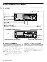
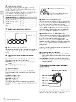
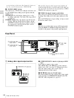
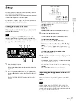
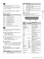
Analog audio signal output section
a
AUDIO OUTPUT (analog audio signal output) 1/3
and 2/4 connectors (XLR 3-pin, male)
These output two channels of analog audio.
For 4-channel audio, you can use the INTERFACE
SELECT >AUDIO OUTPUT item of the setup menu
to select whether to output channels 1 and 2, or
channels 3 and 4 (factory default setting: channels 1 and
2).
You can set the output level with the setup menu item
AUDIO CONTROL >LEVEL SELECT (factory default
setting: +4 dB)
.
b
AUDIO MONITOR connectors (phono jack)
These output audio signals for monitoring.
You can select the channels to monitor with MONI CH and
MONI SEL on the HOME page of the function menu
3
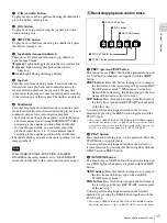
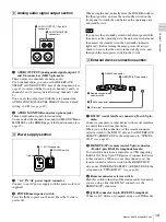
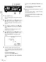
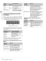
Power supply section
a
-
AC IN (AC power input) connector
Connect to an AC power supply with the power cord (not
supplied).
b
POWER (main power) switch
Press the
+
side to power on the unit. Press the
a
side to
power off.
When using the unit, normally leave the POWER switch in
the
+
(on) position, and use the on/standby switch on the
front panel to switch the unit between the operating state
and standby state.
If you press the on/standby switch on the front panel while
the unit is in the operating state, the unit saves its data and
then enters the standby state (the on/standby indicator
lights red). Before turning the main power off, always
check to be sure that the unit is in the standby state, and
then push the main power switch to the
a
side.
4
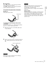
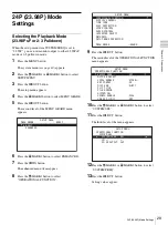
External device connection section
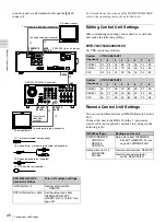
a
RS232C (serial interface) connector (D-sub 9-pin,
male)
Connect a computer or other device with a serial interface
to control this unit from that device.
When you use this connector, set the remote connector
selector switch to the RS232C side, and set INTERFACE
SELECT >REMOTE I/F in the setup menu to “9PIN/RS-
232C”
.
b
REMOTE(9P) (remote control 9-pin) connector
(D-sub 9-pin, RS-422A compliant, female)
To control this unit from a controller or VTR supporting
the RS-422A Sony 9-pin VTR protocol, connect the device
to this connector. When you use this connector, set the
remote connector selector switch to the REMOTE(9P)
side, and set INTERFACE SELECT > REMOTE I/F in the
setup menu to “9PIN/RS232C”
.
c
Remote connector selector switch
Push this switch to the side of the remote control connector
you are using, either the RS232C connector or the
REMOTE (9P) connector.
d
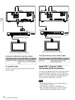
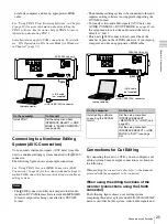
S400 connector (6-pin, IEEE1394 compliant)
Connect a DV device or computer using an i.LINK cable.
AUDIO OUTPUT
1/3
2/4
AUDIO MONITOR
R
L
1
AUDIO OUTPUT 1/3 and 2/4
connectors
2
AUDIO MONITOR
connectors
POWER
-
AC IN
1
-
AC IN connector
2
POWER switch
Note
RS232C
REMOTE(9P)
S400
1
RS232C connector
2
REMOTE(9P) connector
3
Remote connector
selector switch
4
S400 connector
5
U
terminal


