background image

1-5 (E)

PDBK-S1500

1-3.  Settings after Installation 

Check procedure

1.  While pressing the 

[PAGE/HOME]

 button and the 

[SHIFT]

 button simultane-

ously, press the 

[MENU]

 button. 


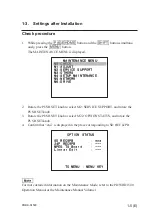
The MAINTENANCE MENU is displayed. 

2.  Rotate the PUSH SET knob to select M2: SERVICE SUPPORT, and rotate the 

PUSH SET knob. 

3.  Rotate the PUSH SET knob to select M22: OPTION STATUS, and rotate the 

PUSH SET knob. 

4. Con

fi

 rm that “ena” is displayed in the place corresponding to SD REC & PB.

n

For more detailed information on the Maintenance Mode, refer to the PDWHD1500 
Operation Manual or the Maintenance Manual Volume 1.

    MAINTENANCE MENU

M0:CHECK

M1:ADJUST

M2:SERVICE SUPPORT

M3:OTHERS

M4:SETUP MAINTENANCE

M5:NETWORK

M6:DRIVE

    MAINTENANCE MENU

M0:CHECK

M1:ADJUST

M2:SERVICE SUPPORT

M3:OTHERS

M4:SETUP MAINTENANCE

M5:NETWORK

M6:DRIVE

      OPTION STATUS
SD REC&PB        : ena

24P REC&PB       : ---

MPEG TS Board    : ---

Linear Edit      : ---

     TO MENU : MENU KEY

      OPTION STATUS
SD REC&PB        : ena

24P REC&PB       : ---

MPEG TS Board    : ---

Linear Edit      : ---

     TO MENU : MENU KEY
Summary of Contents for PDBK-S1500

Page 1: ...nleitung ist nur für qualifiziertes Fachpersonal bestimmt Alle Wartungsarbeiten dürfen nur von qualifiziertem Fachpersonal ausgeführt werden Um die Gefahr eines elektrischen Schlages Feuergefahr und Verletzungen zu vermeiden sind bei Wartungsarbeiten strikt die Angaben in der Anleitung zu befolgen Andere als die angegeben Wartungsarbeiten dürfen nur von Personen ausgeführt werden die eine speziell...

Page 2: ...es the information on installing the PDBK S1500 Related manuals Besides this Installation Manual the following manual is prepared for PDBK S1500 PDW HD1500 Maintenance Manual Available upon request This manual describes the detailed maintenance information and repair information of the PDW HD1500 and the respective options that are required for parts level service For obtaining contact your local ...

Page 3: ...n This optional board can run on the PDW HD1500 containing software version V1 2 or higher If software version of the PDW HD1500 is any version before V1 2 update the software version of the PDW HD1500 Refer to the PDW HD1500 Maintenance Manual Volume 1 1 10 Firmware Update On installation The PDBK S1500 consists of the DU 477A board Install the PDBK S1500 and check that the PDK S1500 is properly ...

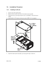
Page 4: ... HPR 23 board connector CN801 4 Attach the DU 477A board with the two screws PSW2 6 x 6 supplied 5 Attach the bottom panel assembly by reversing the steps of removal Bottom panel assembly DU 477A board B3 x 6 B3 x 6 CN1 PSW2 6 x 6 HPR 23 board CN801 Main unit bottom side should face upward Bottom panel assembly DU 477A board B3 x 6 B3 x 6 CN1 PSW2 6 x 6 HPR 23 board CN801 Main unit bottom side sho...

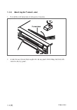
Page 5: ...2 2 Attaching the Format Label 1 Peel off the old format label with a pair of tweezers 2 Attach the new format label supplied to the top panel while fitting the label with cutout on the top panel Format label Format label ...

Page 6: ...irm that ena is displayed in the place corresponding to SD REC PB n For more detailed information on the Maintenance Mode refer to the PDWHD1500 Operation Manual or the Maintenance Manual Volume 1 MAINTENANCE MENU M0 CHECK M1 ADJUST M2 SERVICE SUPPORT M3 OTHERS M4 SETUP MAINTENANCE M5 NETWORK M6 DRIVE MAINTENANCE MENU M0 CHECK M1 ADJUST M2 SERVICE SUPPORT M3 OTHERS M4 SETUP MAINTENANCE M5 NETWORK ...

Page 7: ...Sony Corporation PDBK S1500 WW J E 4 116 915 01 Printed in Japan 2008 9 16 2008 ...

Reviews: