


Confidential
PCG-
GRX510/GRX510K/GRX510P/
GRX550/GRX550K/
PCG-GRX550P/GRX570/GRX570K/GRX570P/GRX590/
PCG-GRX590K/GRX590P (AM)
(END)
3-2
3-1
CHAPTER 3.
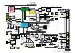
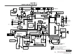
BLOCK DIAGRAM
Vide Memory
K4D623238B
x 2pcs
Memory
CONTROLLER
HUB (MCH)
593 FCBGA
IO Control Hub
ICH3-m
FW82801CAM
Internal
HDD
PCG-GRX Series BLOCK DIAGRAM Rev.0.51
PHONE
OUT
RJ11
MIC
IN
RJ45
MS
CONN
Pentium 4
Processor
512KB L2
478pins
uFCPGA
PCI BUS(3.3V)
AGP
x
4
200
MHz Memory Bus
(DDR)
CardBus/16bitCard
PC Card
Connector
2 Slot
H8S/2149
KBC/EC
SPIC
Graphics
M7-P
(ATI)
LCD CONN
Cable
Ether
PHY
Internal KeyBoard
Membrane
JOG
Controller
VGA DSUB-15
LPC
Memory
Stick
Module
i.LINK0
AC LINK
H
ea
d
p
h
o
n
e
M
IC
Sp
ea
ke
r
Speaker
L&R
Super I/O
SMsC
LPC47N227
I/O Expander
& SM BUS MUX
LID
Serial
Parallele
Refer to Clock Generator
Block Diagram
SMBUS2
USB Right
CONN
TouchPad
JOG
EEPROM
For VID
EEPROM
For i.LINK
MDC
(Modem
Daughter
Card)
Module
CPU Local Bus
EEPROM
For Password
USB Left
CONN
USB Rear
CONN
i.LINK
Dock-VGA DB-15
Dock-VGA DB-15
Serial
Parallele
RJ-45
RJ45
VGA
DB-15
Video-
Out
USB
CONN
USB
CONN
LineOut
Port0-5
Optical
Drive
Pr
im
ar
y
S
eco
nd
a
r
y
IDE(ATA100)
AMP, etc.
L
in
e
O
u
t
RJ-45
RJ-45
Parallele
PS/2
CLKGEN
IMI
9870GTD
Port Repricator
Parallele
Parallele
i.LINK0
Port-4
Port-0
Port-3
Port-2
Port-1
Port-5
RJ-45
RJ-11
RJ-11
1st
Battery
Power
Circuit
DC Jack
DDR(SO-DIMM)
SMBUS2
SMBUS2
SMBUS1
SMBUS0
PS/2
Reserved
Reserved
Port-3
Port-2
DC Jack
Serial
DCin
DCin
BATTERY1
BATTERY2
BATTERY1
2nd
Battery
BATTERY2
FAN0
ATF0
FAN1
ATF1
PS/2
Other
Control
DDR(SDRAM)
FWH
8Mb
(Flash BIOS
ROM)
Multi Purpose Bay
LINE-OUT
AV
Out
Audio-Out
S-Video-Out
Audio
L-out
Audio
R-out
TV-Out
TV-Out
S-Video-Out
TV-Out
USB3
USB2
USB3
USB2
Audio
YMF753
(Yamaha)
SONY
16inch UXGA
TV-Out
CARDBUS
& i.LINK
RICOH
R5C552
Bus #2 Dev #5
EEPROM
For LAN
EEPROM
For ClockGEN
EEPROM
On DIMM1
For SPD
EEPROM
On DIMM2
For SPD
15inch XGA