background image

Sony 

not

e

book

 us

e

r gui

d

e

Using your notebook

16

n

N

Back


* Not on PCG-FX101.

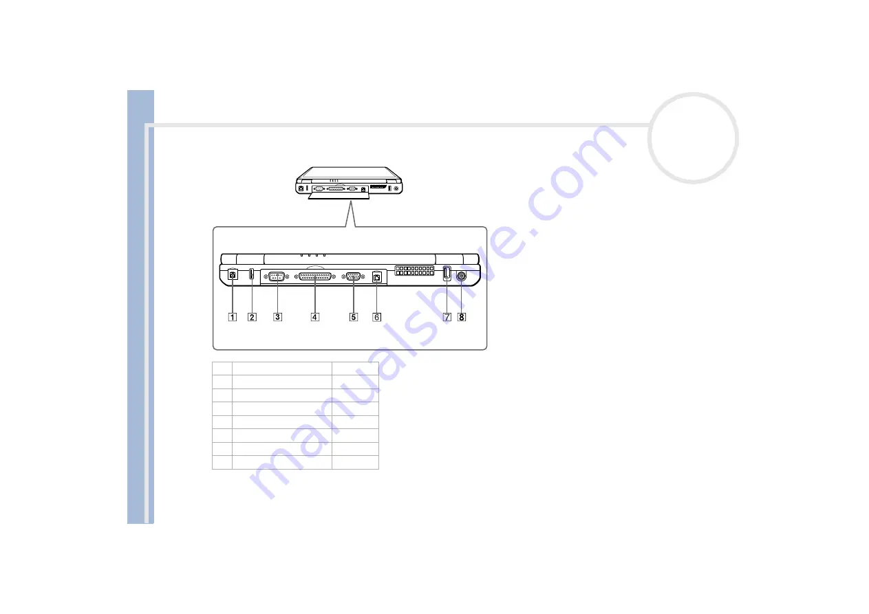
There is a ventilation slot located near the USB connector. Do not cover the ventilation slot when your computer is on.

1

phone line jack

(page 50)

2

USB  connector

(page 67)

3

serial connector

(page 69)

4

printer

(page 69)

5

monitor connector

(page 59)

6

ethernet connector*

(page 75)

7

USB  connector

(page 67)

8

DC  In

(page 18)

Summary of Contents for PCG-FX103/K

Page 1: ...N Sony Notebook User Guide P C G F X 1 0 1 P C G F X 1 0 3 P C G F X 1 0 5 K P C G F X 1 0 8 K P C G F X 1 0 9 K ...

Page 2: ...on Corporation and other rights owners Use of this copyright protection technology must be authorized by Macrovision Corporation and is intended for home and other limited viewing uses only unless otherwise authorized by Macrovision Corporation Reverse engeneering or dissambly is prohibited Sony Corporation reserves the right to make any modification to this manual or the information contained her...

Page 3: ...eets the ENERGY STAR guidelines for energy efficiency The International ENERGY STAR Office Equipment Program is an international program that promotes energy saving through the use of computers and their office equipment The program backs the development and dissemination of products with functions that effectively reduce energy consumption It is an open system in which business proprietors can pa...

Page 4: ...amages that are not covered by the guarantee To avoid electrical shock do not open the cabinet Refer servicing to qualified personnel only To prevent fire or shock hazard do not expose your VAIO notebook to rain or moisture Avoid using the modem during a storm Do not use the modem or a telephone to report a gas leak in the vicinity of the leak To change the backup battery please contact your neare...

Page 5: ... make sure that the socket outlet is easily accessible Never touch uninsulated telephone wire or terminals unless the telephone line has been disconnected at the network interface Optical disk The use of the optical instruments supplied with your notebook will cause eye hazard As the laser beam used in this product is harmful to eyes do not attempt any disassembling process For servicing refer to ...

Page 6: ...th EN 55022 Class B and EN 50082 1 for use in following areas residential commercial and light industrial This product has been tested and found compliant with the limits set out in the EMC Directive for using connection cables shorter than 3 metres 9 8 feet The optical disk drive is classified as a CLASS 1 LASER PRODUCT and complies with the Laser Product Safety Standard EN 60825 1 Repair and mai...

Page 7: ...er Discard used batteries according to the manufacturer s instructions The battery pack used in this device may present a fire or chemical burn hazard if mistreated Do not disassemble heat above 100 C 212 F or incinerate Keep away from children Your notebook is equipped with an internal backup memory battery For changing this battery please contact VAIO Link http www vaio link com In some areas th...

Page 8: ...antage of today s advanced multimedia applications games and entertainment software Multimedia features Enjoy the speakers to listen to audio and video CDs Interconnectivity Your computer has ethernet and i LINKTM functionalities i LINK is a bidirectional digital interface for exchanging data Windows Your system includes the latest operating system from Microsoft Communications Access popular onli...

Page 9: ...add functionality by connecting various peripherals Getting Help explains the support options available to you and offers basic troubleshooting tips Precautions provides facts and advice about using your notebook Specifications provides details on your computer drivers and accessories 2 Refer to your Software Guide for information on the bundled software and the Sony applications About the Softwar...

Page 10: ...eo cable PCG FX101 CD ROM drive PCG FX103 PCG FX105K PCG FX108K DVD ROM drive PCG FX109K CD RW DVD ROM drive 1 main unit 5 rechargeable battery pack 9 phone plug country specific 2 product recovery CD ROMs 6 removable floppy disk drive installed at factory 10 phone cable 3 documentation pack 7 weight saver 11 power cord 4 AC adapter 8 video cable 12 optical disk drive installed at factory ...

Page 11: ...f you 1 Keep your forearms horizontal 2 with your wrists in a neutral comfortable position 3 while using the keyboard touchpad or external mouse Let your upper arms hang naturally at your sides Have breaks during sessions with your computer Excessive use of the computer may strain muscles or tendons Furniture and posture Sit in a chair with good back support Adjust the level of the chair so your f...

Page 12: ...create glare and reflection on the display Use indirect lighting to avoid bright spots on the display You can also purchase accessories for your display that help reduce glare Proper lighting adds to your comfort and work effectiveness Placement of an external display When using an external display set the display at a comfortable viewing distance Make sure the display screen is at eye level or sl...

Page 13: ... connectors Right Except on PCG FX101 PCG FX101 CD ROM drive PCG FX103 PCG FX105K PCG FX108K DVD ROM drive PCG FX109K CD RW DVD ROM drive PCG FX101 has no floppy disk drive Phone cable and connectors are TNV Telecommunications Network Voltage according to EN60950 1 PPK buttons page 51 3 optical disk drive page 35 2 power button page 27 4 multi purpose bay for weight saver or floppy disk drive page...

Page 14: ...nnector and power cord hazardous voltage according to EN 60950 All other connectors for this notebook are SELV Safety Extra Low Voltage according to EN 60950 1 TV Out connector page 61 4 i LINK connector page 72 2 microphone connector page 65 5 PC Card slots page 44 3 headphone connector page 64 6 battery bay page 18 ...

Page 15: ...3 7 battery 1 and 2 indicators page 32 2 speakers page 33 8 hard disk drive indicator page 32 3 keyboard page 30 9 Num Lock indicator page 32 4 touchpad page 34 10 Caps Lock indicator page 32 5 left right buttons page 34 11 Scroll Lock indicator page 32 6 power indicator page 32 ...

Page 16: ...ation slot located near the USB connector Do not cover the ventilation slot when your computer is on 1 phone line jack page 50 2 USB connector page 67 3 serial connector page 69 4 printer page 69 5 monitor connector page 59 6 ethernet connector page 75 7 USB connector page 67 8 DC In page 18 ...

Page 17: ...otebook user guide Using your notebook 17 n N Bottom The port replicator connector cover of the PCG FX101 does not open 1 port replicator connector cover page 55 2 release lever page 55 3 tilt stands page 11 ...

Page 18: ...proceed as follows 1 Plug the cable attached to the AC adapter 1 into the DC In connector 2 on the computer 2 Plug one end of the power cord 3 into the AC adapter 3 Plug the other end of the power cord into an AC outlet Use your notebook only with the supplied AC adapter To disconnect your notebook completely from mains voltage unplug the AC adapter Make sure that the socket outlet is easily acces...

Page 19: ...e battery pack supplied with your computer is not fully charged at the time of purchase Inserting the battery pack To insert the battery pack proceed as follows 1 Open the cover of the battery bay 2 Insert the battery pack with the label facing down into the battery bay on the left side of the computer 3 Close the cover of the battery bay until it clicks When the computer is directly connected to ...

Page 20: ...ttery is 85 full the battery indicator light turns off This process takes approximately one and a half hours for the PCG FX101 and PCG FX103 and approximately three hours for the PCG FX105K PCG FX108K and PCG FX109K To charge the battery completely continue charging for an additional hour There are two battery indicator lights on the computer 1 Indicates the status of the battery pack in the batte...

Page 21: ...arging a partially discharged battery does not affect battery life The battery indicator light is on while you use the battery pack as a power source When the battery life is nearly depleted the battery indicator starts flashing For some software applications and some peripheral devices your computer may not enter Hibernate mode when battery life is low To avoid loss of data when using battery pow...

Page 22: ... as follows 1 Turn off the computer 2 Open the cover of the battery bay 3 Pull out the battery pack 4 Close the cover of the battery bay You may lose data if you remove the battery pack while the computer is on and not connected to the AC adapter or if you remove the battery while the computer is in Standby mode ...

Page 23: ...ck you insert first charges first The battery pack you insert second charges when the first battery pack is 85 percent full You can monitor which battery pack is charging by observing the battery indicator lights Inserting the second battery pack To insert a second battery pack proceed as follows 1 If the floppy disk drive is in the multi purpose bay 1 remove the device 2 Insert the battery pack 2...

Page 24: ...ver toward the front of the computer to lock it If you attach two battery packs you can remove one of them without shutting down the computer When removing one battery pack make sure that the other battery pack indicator is on If the indicator of the battery pack your are going to remove is on right click the battery icon on the taskbar and click the switch discharge battery menu ...

Page 25: ...ttery pack To charge the second battery pack proceed as follows 1 Keep the battery pack 1 3 in the computer while it is connected to AC power The battery indicator 2 flashes while the battery is charging 2 When the battery indicator stops flashing the battery is fully charged ...

Page 26: ... the second battery pack proceed as follows 1 Slide the eject lever on the bottom of the weight saver in the direction of arrow 1 2 Slide the release lever on the bottom of the computer in the direction of arrow 2 3 Remove the weight saver 4 Pull out the battery pack 5 Reinsert the weight saver ...

Page 27: ...ess the power button 2 of the computer until the green power indicator 3 light turns on 3 If necessary press Fn F5 to adjust the brightness controls for the LCD display To increase the brightness use the up or right arrow keys To decrease use the down or left arrow keys Fn F5 is only possible once you are in Windows If you press the power button for more than four seconds the computer will turn of...

Page 28: ...ripheral connected to your computer Respond to any prompts warning you to save documents If you are unable to shut down your computer Close all software in use Remove the PC Cards if inserted To do so double click the Unplug or Eject Hardware icon in the taskbar Select the hardware you want to unplug and click Stop Disconnect any USB devices Then press the Ctrl Alt Delete keys at the same time to ...

Page 29: ...antee Protect your investment See the Guarantee sheet for the terms and conditions and refer to your Customer Service Guide for more information To register your Sony Notebook proceed as follows 1 Click on the Welcome button on your desktop 2 Click Next 3 Click Internet 4 Fill in your Registration card fields 5 Scroll down to the bottom of the form and click Send 6 Click OK You must connect your p...

Page 30: ...e twelve function keys along the top of the keyboard are used to perform designated tasks For example in many applications F1 is the Help key The task associatd with each function key may vary from one application to the other Print Screen key 3 The Print Screen key takes an electronic snapshot of the screen and moves it to the Windows Clipboard You can then paste the screenshot into a document an...

Page 31: ...ing the Save command from a menu you can hold down Ctrl and press S referred to as Ctrl S The Shift key is used to produce capital letters or special symbols such as and Windows key 9 The key with the Windows logo displays the Windows Start menu it is equivalent to clicking the Start button on the taskbar Fn key 10 The Fn key is used in combination with other keys to execute commands Combinations ...

Page 32: ...r turn off the computer when this indicator light is on The hard drive is not being accessed Num Lock Turns on when the number keys in the numeric keypad are active Turns off when the alphanumeric character keys in the keypad area are active Caps Lock Turns on when the letters appear in uppercase as you type The Shift key lowers the case of typed letters when Caps Lock is on Turns off when the let...

Page 33: ...lume press Fn F4 and then or Fn F5 brightness control Adjusts the brightness of the LCD To increase light intensity press Fn F5 and then or To decrease light intensity press Fn F5 and then or Fn F7 switch to the external display Toggles between the LCD external display connected to the monitor connector and both LCD and external display Fn F8 Toggles between the LCD and both LCD and TV only for mo...

Page 34: ...e pointer 2 on an item or object click Press the left button 3 once double click Press the left button twice right click Press the right button 4 once In many applications this action displays a shortcut menu drag Slide one finger while pressing the left button scroll Move your finger along the right edge of the touchpad to scroll vertically Move your finger along the bottom to scroll horizontally...

Page 35: ...r computer is equipped with an optical disk drive PCG FX101 CD ROM drive PCG FX103 PCG FX105K PCG FX108K DVD ROM drive PCG FX109K CD RW DVD ROM drive To insert a disk proceed as follows 1 Turn on the computer 2 Press the Eject button 1 to open the optical disk drive The tray slides out ...

Page 36: ...ly over the disk drive hub fingers If you do not seat the disk firmly you could damage your disk drive and you may not be able to open the tray When you finish using a disk wait until the LED indicator turns off and then press the Eject button to remove the disk If the disk does not come out when you press the Eject button go to Windows Explorer Select the drive click the right button of your mous...

Page 37: ...ed to disable it Do not use resident disk utilities and resident utilities to speed up access of disks because they may cause unstable operation Make sure that the screensaver is deactivated Region codes indicators are labeled on the DVD disks to indicate in which region and what type of player can play the disk Unless a 2 or all is labeled on your DVD disk or on the packaging you cannot play the ...

Page 38: ... If you do not format the disk your computer will not recognize it To make a CD R to which data has been written readable on a CD ROM drive you need to close the session when you eject it To complete this process follow the instructions included with your software Always use the AC adapter as the power source for your computer when you are writing data to a CD RW or CD R Using battery power may re...

Page 39: ... to exit and close all other applications Exit anti virus software before writing data to a disk Never touch the surface of the disk Fingerprints and dust on the surface of a disk may cause writing errors Do not put your notebook into power saving mode while using DirectCD to write data or while using Easy CD Creator If you set the display resolution higher than the default DVD video may not be pl...

Page 40: ... 1 If another device is in the multi purpose bay remove the device 2 Pull out the guide 1 of the weight saver and slide the weight saver in the direction of the arrow 2 until it clicks To remove the weight saver proceed as follows 1 Slide the eject lever of the weight saver in the direction of arrow 1 2 Slide the release lever on the bottom of the computer in the direction of arrow 2 ...

Page 41: ...uipped with an internal removable floppy disk drive Except on PCG FX101 Inserting the floppy disk drive Inserting a diskette To insert a diskette proceed as follows 1 Hold the diskette 1 with the label side facing up 2 Gently push the diskette into the floppy disk drive 2 until it clicks into place ...

Page 42: ...n N Removing a diskette To remove a diskette proceed as follows 1 Wait untill the LED indicator 1 turns off 2 Press the eject button 2 to remove the diskette Do not press the Eject button when the LED indicator is turned on Otherwise data may be lost ...

Page 43: ...f the arrow 3 Slide the drive 2 out of the multi purpose bay 4 Insert the weight saver Re inserting the floppy disk drive To re insert the floppy disk drive proceed as follows 1 Turn off the computer 2 If another device is in the multipurpose bay 1 remove the device 3 Insert the floppy disk drive 2 into the multi purpose bay with the metallic part up 4 Continue pushing the drive into the bay until...

Page 44: ...ard slots 1 2 PC Cards allow you to connect portable external devices Inserting a PC Card To insert a PC Card proceed as follows 1 Push the Release button The Release button pops out 2 Push the Release button The PC Card slot comes out 3 Insert the PC Card into the PC Card slot front label facing up ...

Page 45: ...ard You can use Sony Notebook Setup to disable devices Be sure to use the most recent software driver provided by the PC Card manufacturer If an mark appears on the Device Manager tab in the System Properties dialog box remove the software driver and then reinstall it You do not need to shut down the computer before inserting or removing a PC Card Do not force a PC Card into the slot It may damage...

Page 46: ...tton to eject the card 10 Gently grasp the card and pull it out 11 If the PC Card release button is still out push the PC Card release button in the notebook If you unplug the PC Card from the computer when this is still turned on your system might crash and you might lose data that you did not save before Before you remove the PC Card click the PC Card icon in the taskbar and close the card Close...

Page 47: ...era recorder or a digital still camera Before using Memory Sticks you should back up important data To avoid damaging data Do not remove a Memory Stick or turn off the power while the access light is on Do not use Memory Sticks in locations that are subject to static electricity or electrical noise Do not touch the Memory Stick connector with your finger or metallic objects Do not attach labels ot...

Page 48: ...e PC Card adapter into the connector 3 on your computer label facing up and push it gently 6 The Memory Stick is automatically detected by your system and appears in your My Computer window as a local drive under the appropriate letter depending on the configuration of your computer When your Memory Stick is detected the Unplug or Eject Hardware icon appears in the taskbar Hold the Memory Stick wi...

Page 49: ...n the Stop a Hardware device dialog box confirm that the device can be safely removed from the system 5 Click OK You get the message that it is safe to remove the device 6 Click OK 7 Click Close 8 Press the PC Card release button so that it pops out 9 Push the PC Card release button to eject the card 10 Gently grasp the card and pull it out Always remove the Memory Stick gently or it may pop out u...

Page 50: ...you to plug the phone line into the wall jack We recommend you to use the supplied plug because the usage of any other phone plug can decrease the connection quality Your computer cannot be connected to a coin operated telephone and may not work with multiple phone lines or a private branch exchange PBX If you connect the modem to a parallel connected phone line the modem or the other connected de...

Page 51: ...essing it or use it in combination with 3 keys on your keyboard Shift Ctrl or Alt When your computer is off press a PPK and the system will be powered and launch the appropriate application The factory settings for the buttons are P1 opens the Club VAIO Website P2 opens your e mail application Outlook Express P3 puts your machine in Standby mode Sleep The factory settings for the PPK buttons in co...

Page 52: ...ter automatically enters Hibernate mode when the remaining battery charge drops below 7 percent regardless of the power management setting you select If the battery level falls to below 10 percent you should either attach the AC adapter to recharge the battery or shut down your computer and insert a fully charged battery Using Normal mode This is the normal state of your computer when it is in use...

Page 53: ...than Hibernate Standby uses more power than Hibernate Using Hibernate mode The state of the system is saved on the hard disk and power is turned off The power indicator light is off in this mode To activate Hibernate mode proceed as follows Press Fn F12 Or Use the PowerPanel utility To return to Normal mode proceed as follows Turn on the computer by pressing the power button The computer returns t...

Page 54: ...r connecting all cables Turn on the computer only after turning on all peripherals Connecting a port replicator page 55 Connecting an external display page 59 Connecting external speakers page 64 Connecting an external microphone page 65 Connecting an external mouse or keyboard page 66 Connecting a Universal Serial Bus USB mouse page 67 Connecting a printer page 68 Connecting an i LINK device page...

Page 55: ...cept on PCG FX101 All connectors are SELV Safety Extra Low Voltage according to EN60950 The port replicator can be powered only with the AC adapter supplied with your notebook Do not remove the AC adapter from the port replicator this may cause data damage or hardware malfunctions 1 serial connector page 69 5 3 USB ports page 67 page 68 2 parallel port page 69 6 mouse keyboard connector page 66 3 ...

Page 56: ...he port replicator To attach your computer to the port replicator proceed as follows 1 Turn off the computer and disconnect all peripherals 2 On the bottom of the computer lift the port replicator port cover 3 Attach the bottom of the computer to the port replicator connector until it clicks ...

Page 57: ...ator light turns green 7 Turn on the computer When you use the port replicator for the first time the installation of the network drivers starts automatically When attaching your computer to the port replicator do not attempt to insert or remove the battery pack Lifting and turning the computer with the attached port replicator may cause a temporary loss of power You do not need to use the floppy ...

Page 58: ...port replicator 1 to disengage the computer from the port replicator 3 Lift the computer away from the port replicator 4 Close the port replicator connector cover on the bottom of your computer It is extremely important to close the port replicator connector cover after removing your computer from the port replicator If the cover is left open dirt may get inside and damage the computer To disconne...

Page 59: ...adapter and the power cord before connecting the external display Connect the power cord after connecting all other cables Turn on the peripherals then turn on your computer Connected external displays are used as second screens On Windows systems only you can also use an external display to set up a virtual desktop 108 Connecting a computer display To connect a computer display proceed as follows...

Page 60: ...ia computer display that includes built in speakers and a microphone To connect a multimedia computer display proceed as follows 1 Plug the display cable 1 in the monitor connector 2 on the computer 2 Plug the speaker cable 3 in the headphone connector 4 on the computer 3 Plug the microphone cable 5 in the microphone connector 6 on the computer ...

Page 61: ...le 1 into the TV Out connector 2 yellow and the other end into the TV 2 Plug one end of the sound cable 3 into the headphone connector 4 and the other end into the TV 3 Plug the power cord of the TV 5 into an AC outlet 4 Switch the input channel of the TV to external input 5 Set up the TV configuration system Only on PCG FX105K PCG FX108K PCG FX109K ...

Page 62: ...ion 1 Eject your DVD from your computer 2 Once the DVD is ejected toggle between your LCD and your TV with the combination Fn F8 Your image displays now on both LCD and TV Re insert your DVD to launch your DVD software If the display resolution of your computer is more than 800 x 600 dots a part of the image cannot be displayed on your TV The hidden area on your TV can be seen by moving the cursor...

Page 63: ...e audio cable 3 not supplied into the earphone connector 4 identified by the symbol 3 Plug the RGB signal cable and the audio cable into the connectors of the projector 5 4 Connect the power cord 6 of the projector into an AC outlet You may not be able to display the computers s LCD and the external display together depending on the types of computer display and projector used You can toggle the o...

Page 64: ...nnect external speakers proceed as follows 1 Plug the speaker cable 1 into the earphone connector 2 2 Plug the other end of the speaker cable into the external speaker 3 Turn down the volume of the speakers before you turn them on Make sure your speakers are designed for computer use Do not place diskettes on the speakers their magnetic field may damage the data on the diskettes ...

Page 65: ...hone If you need to use a sound input device for example to chat on the Internet you need to plug in an external microphone To connect an external microphone proceed as follows 1 Locate the microphone connector identified by the symbol 2 Plug the microphone cable 1 into the microphone connector 2 Make sure your microphone is designed for computer use ...

Page 66: ...d and mouse is not supported Before you connect or disconnect the mouse or the keyboard turn off the computer The mouse keyboard connector requires a PS 2 style plug or adapter PCG FX101 cannot connect a port replicator To connect an external mouse or keyboard proceed as follows 1 Locate the mouse keyboard connector 1 identified by the symbol 2 Plug the mouse cable 2 or the keyboard cable 3 into t...

Page 67: ...he back of the port replicator 2 Plug the USB mouse cable 2 into the USB connector You can use your USB mouse 3 PCG FX101 cannot connect a port replicator You do not need to shut down the computer before connecting or disconnecting a USB peripheral The USB mouse software driver is preinstalled on your notebook therefore you only need to plug the USB mouse into the USB connector and you can start w...

Page 68: ... Windows to your computer To connect a printer using the USB connector proceed as follows 1 Plug an optional USB printer cable 1 into the USB connector 2 identified by the symbol on your computer and printer 2 Plug the printer 3 power cord into an AC outlet Before using the printer you may need to change the Printer settings in the Sony Notebook Setup software Turn off your computer and the printe...

Page 69: ...ct a printer using the printer connector proceed as follows 1 Plug the printer cable 1 supplied with the printer into the printer connector 2 identified by the symbol 2 Plug the printer power cord 3 into an AC outlet Before using the printer you may need to change the Printer settings in the Sony Notebook Setup software ...

Page 70: ...es generally powered by i LINK connectors The i LINK connector supports transfer rates up to 400 Mbps however the actual transfer rate depends on the transfer rate of the external device The i LINK features available may vary depending on the software applications you use Refer to the documentation that came with your software for more information i LINKTM cables compatible with your VAIO notebook...

Page 71: ...camera recorder 2 Launch the DVgate application On Sony digital video cameras connectors labeled DV Out DV In Out or i LINK are i LINK compatible The Sony digital video camera recorder is an example your digital video camera recorder may need to be connected differently If your digital video camera recorder includes a Memory StickTM slot you can copy images from it to your computer via a Memory St...

Page 72: ...uter If you have Windows Millennium Edition installed on your machine You can connect your notebook to another VAIO notebook using an i LINK cable 1 not supplied With Smart Connect on your notebook you can copy edit or delete files on another VAIO notebook that has also Windows Millennium Edition installed or that has Smart Connect 3 0 You can also print a document on a printer connected to anothe...

Page 73: ...and a CONTROL A1 CONTROL A1 II cable Then connect the Sony MiniDisc deck to your notebook using a CONTROL A1 cable This allows you to record and edit your MiniDiscs via your notebook You can now Enjoy complete editing and assembly functions like changing the order of the numbers on your MiniDisc Use the touchpad or mouse to play and edit MiniDiscs and the keyboard to enter disk and track titles to...

Page 74: ...t on your CD player and the other end to the digital optical output input on your MiniDisc 4 Turn on all the devices 5 Launch MD Player Refer to your MiniDisc deck and CD player manuals to check the specifications For further information or if you are not sure of the connection capabilities of your devices please contact your dealer To perform a copy using your notebook you need two CONTROL A1 or ...

Page 75: ...t to the network consult your Network Administrator Not on PCG FX101 The default settings make your computer unable to connect to the network To connect to the network check Ethernet in Sony Notebook Setup For more information about connecting your notebook to the network please consult the Hardware troubleshooting section of the Vaio Link website How to troubleshoot network problems Do not plug a...

Page 76: ...rted gives you a list of the items you find in the box and a summary of the bundled applications Online user guides on your Documentation CD ROM The Hardware guide explains how to use your computer connect peripheral devices It contains a list of specifications of your computer and accessories The Software guide lists the pre installed software titles and explains how to use the utility programs a...

Page 77: ...contacting VAIO Link About the computer and software My computer does not start Check that the computer is plugged into a power source and that it is turned on Check that the power indicator on the front panel of the computer indicates that the power is on Check that the battery packs are inserted properly and that they are charged Make sure there is no diskette in the floppy disk drive Confirm th...

Page 78: ...r 3 Turn on the computer and press F2 when the Sony logo appears The BIOS setup menu screen appears 4 Press the arrow keys to select the Exit menu 5 Press the arrow keys to select Get Default Values and then press Enter The message Load default configuration now appears 6 Make sure that Yes is selected and then press Enter 7 Press the arrow keys to select Exit save changes and then press Enter The...

Page 79: ...he battery pack from your computer My computer locks up Windows 2000 If you suspect one application is locking your system you can try to stop it To do this press Ctrl Alt Delete once click Task Manager select the application or the process that is locking your system and then click End Task Windows Millennium Edition If you suspect one application is locking your system you can try to stop it To ...

Page 80: ... connector of your port replicator If you are using a USB mouse check that the appropriate driver and software are properly installed Check that the USB mouse is plugged into the USB connector About the display My LCD does not display anything Check that the computer is plugged into a power source and that it is turned on Check that the power indicator on the front panel of the computer is on Chec...

Page 81: ...a If the DVD disk is inserted in the DVD ROM drive remove the disk Not available on PCG FX101 and PCG FX103 About CD ROMs and diskettes My optical disk drive tray does not open Make sure the computer is turned on Press the Eject button on the optical disk drive If the Eject button does not work you can open the tray by inserting a sharp pointed object into the hole to the right of the Eject button...

Page 82: ...sound check all of the following Make sure the mute setting is off in your DVD player Check the master volume setting in the Audio Mixer If you have connected speakers externally check the volume settings in your computer speakers and check the connections between your speakers and the computer Windows 2000 In the Device Manager check that the correct drivers are installed properly To display the ...

Page 83: ...cation icon a message such as You must insert the application CD into your CD ROM drive appears and the software does not start Some titles require specific files that are located on the application CD ROM Insert the disk and try starting the program again Make sure you place the disk in the tray with the label side facing up The disk tray does not eject even when the Eject button is pressed Check...

Page 84: ... the speakers are properly connected and the volume is turned up If the speakers have a mute button make sure it is off If batteries power the speakers check that the batteries are inserted properly and that they are charged If you have connected an audio cable to the Headphone connector disconnect the cable The sound of my notebook s fan is too loud Use the PowerPanel utility to change the Therma...

Page 85: ...rrect on the Dialing Properties tab Windows Millennium Edition If you do not see the Modems icon proceed as follows 1 In Control Panel click Tools and click Folder Options 2 Select the View tab 3 In the Advanced settings dialog box select the option Display all Control Panel options and all folder contents 4 Click OK My modem cannot establish a connection The modem dialing mode may be incompatible...

Page 86: ...cables are properly connected If you are using multiple i LINK devices the combination of the connected devices may cause unstable operation In this case turn off the power of all connected devices and disconnect unused devices Check the connection and then turn on the power again My PC Card is not working Make sure the PC card is compatible with your version of Windows Use the Sony Notebook Setup...

Page 87: ...to DV device failed Check the power and cable connections to the DV device and try the operation again Close all open applications and restart your computer Frequent recording of images to a digital video device while using DVgate sometimes causes this error About power management The Power Management setting is not responding Your notebook s operating system may become unstable if a lower power s...

Page 88: ...f you need assistance Adding and removing memory In the future you may want to install memory modules to expand the functionality of your computer You can increase the memory by installing optional memory modules Be careful when adding memory Mistakes on installation or removal of the memory module may cause a malfunction For memory upgrades use only PC100 CL2 SDRAM SO DIMM gold lead contacts Elec...

Page 89: ...f the chassis while performing the procedure Do not open the memory module package until you are ready to install the module The package protects the module from ESD Use the special bag delivered with the memory module or wrap the module in aluminium foil to protect it from electrostatic discharge Do not place the memory module in places subject to Heat sources such as radiators or air ducts Direc...

Page 90: ...e direction of the arrows 1 The memory module is released Pull the memory module in the direction of arrow 2 Close the cover Gently tighten the screws Adding a memory module To add a memory module proceed as follows 1 Shut down your computer and disconnect all peripheral devices 2 Unplug the computer and remove the battery packs 3 Wait until the computer cools down 4 Turn your computer upside down...

Page 91: ... Open the cover on the bottom by unscrewing the screw turn counterclockwise Remove the memory module from its packaging Install the memory module 6 Close the computer cover 7 Tighten the screws on the bottom of the computer 8 Turn on the computer ...

Page 92: ...ort time On the other hand it may be easily damaged by mechanical vibration shock or dust Although the hard disk has the safety device in itself to prevent losing data due to mechanical vibration shock or dust you should be careful when handling your computer To avoid damaging your hard disk Do not give a shock to your computer Keep away from magnets Do not place your computer in a location subjec...

Page 93: ...You may however see tiny black points and or bright points red blue or green that continuously appear on the LCD This is a normal result of the manufacturing process and does not indicate a malfunction Avoid rubbing the LCD screen as this can damage the screen Use a soft dry cloth to wipe the LCD screen On using power source Your computer operates on 100V 240V AC 50 60 Hz Do not share the AC outle...

Page 94: ...as radiators or air ducts Direct sunlight Excessive dust Moisture or rain Mechanical vibration or shock Strong magnets or speakers that are not magnetically shielded Ambient temperature of more than 35º C or less than 10º C High humidity Do not place electronic equipment near your computer The electromagnetic field of your computer may cause a malfunction Provide adequate air circulation to preven...

Page 95: ...roduct Recovery CD ROM On handling diskettes Do not open the shutter manually and touch the surface of the diskette Keep diskettes away from magnets Keep diskettes away from direct sunlight and other heat sources On handling CD ROM disks Do not touch the surface of the disk Do not drop or bend the disk Fingerprints and dust on the surface of a disk may cause read errors Proper care of the disk is ...

Page 96: ...en or try to disassemble the battery pack Do not expose the battery pack to any mechanical shock If you are not using the computer for an extended period of time remove the battery pack from the computer to prevent damage to the battery If after fully charging the battery pack the battery power is still low the battery pack may be reaching the end of its life and should be replaced You do not need...

Page 97: ...ot touch the connector with your finger or metallic objects Use only the label supplied with the Memory Stick as a label Do not bend drop or apply strong shock to the Memory Stick Do not disassemble or modify Memory Sticks Do not let cards get wet Do not use or store Memory Sticks in a location subject to Extremely high temperatures such as in a car parked in the sun Direct sunlight High humidity ...

Page 98: ...entium III processor 650 MHz featuring Intel SpeedStep technology Hard disk drive 10 GB Standard RAM 64 MB SDRAM in slot Maximum RAM 512 MB LCD screen 13 3 XGA 1024x768 TFT L2 cache memory 128 KB on die 256 KB on die MPEG MPEG 2 Digital Video Supports full screen playback Graphics Intel 815EM Chipset integrated graphic accelerator Video RAM max 11MB shared with main memory Display cache not availa...

Page 99: ...ading speed up to 8x max DVD ROM reading speed laser diode properties wave length 780 nm and 650 nm laser output 30 2 µW Internal modem built in modem V90 K56Flex 56kbps data fax modem Telecommunication capabilities PSTN data connectivity ethernet network PSTN data connectivity Expansion capabilities two PCMCIA type I two PCMCIA type II or one type III Cards and Cardbus support Built in capabiliti...

Page 100: ...n capabilities on port replicator no port replicator available DC In printer monitor serial 3 USB PS 2 mouse keyboard network Supplied accessories rechargeable battery AC adapter AC power cord phone cable phone plug weight saver rechargeable battery AC adapter AC power cord phone cable phone plug weight saver floppy disk drive Service 1 year free VAIO Link Service Guarantee 1 year guarantee parts ...

Page 101: ...attery and floppy disk drive 3 0 kg 3 0 kg 3 2 kg Operating temperature 5 C to 35 C temperature gradient less than 10 C hour Storage temperature 20 C to 60 C temperature gradient less than 10 C hour Operating humidity 20 to 80 not condensed provided that humidity is less than 65 at 35 C hygrometer reading of less than 29 C Storage humidity 10 to 90 not condensed provided that humidity is less than...

Page 102: ...tium III processor 750 MHz featuring Intel SpeedStep technology Mobile Intel Pentium III processor 850 MHz featuring Intel SpeedStep technology Hard disk drive 20 GB 30 GB Standard RAM 64 MB SDRAM in slot 128 MB SDRAM in slot Maximum RAM 512 MB LCD screen 14 1 XGA 1024x768 TFT 15 0 XGA 1024x768 TFT 15 0 SXGA 1400x1050 TFT L2 cache memory 256 KB on die MPEG MPEG 2 Digital Video Supports full screen...

Page 103: ... and 650 nm laser output 30 2 µW CD RW DVD ROM drive up to 24x max CD ROM reading speed up to 8x max CD R writing speed up to 4x max CD RW writing speed up to 8x max DVD ROM reading speed laser diode properties wave length 785 nm and 660 nm laser output 468 µW Internal modem built in modem V90 K56Flex 56kbps data fax modem Telecommunication capabilities ethernet network PSTN data connectivity Expa...

Page 104: ...E1394 S400 ethernet TV out Connection capabilities on port replicator DC In printer monitor serial 3 USB PS 2 mouse keyboard network Supplied accessories rechargeable battery AC adapter AC power cord phone cable phone plug weight saver floppy disk drive video cable Service 1 year free VAIO Link Service Guarantee 1 year guarantee parts and labour Power requirement 64 35 watts maximum 19 5V DC AC100...

Page 105: ...th 1 battery and floppy disk drive 3 1 kg 3 3 kg 3 2 kg 3 4 kg 3 3 kg 3 5 kg Operating temperature 5 C to 35 C temperature gradient less than 10 C hour Storage temperature 20 C to 60 C temperature gradient less than 10 C hour Operating humidity 20 to 80 not condensed provided that humidity is less than 65 at 35 C hygrometer reading of less than 29 C Storage humidity 10 to 90 not condensed provided...

Page 106: ...B signal 63 speaker 60 64 video 10 61 camera 71 Caps Lock indicator 15 32 CD ROM drive 8 10 35 99 103 CD RW 38 CD RW drive 10 35 38 99 103 charging status 20 combination controls 31 33 connection capability 100 connector DC In 16 18 55 57 earphone 63 64 ethernet 16 55 headphone 14 60 61 i LINK 14 keyboard 55 66 microphone 14 65 monitor 16 55 59 60 63 mouse 55 66 port replicator 56 printer 69 seria...

Page 107: ...10 13 23 41 43 99 Fn key 31 33 function key 30 G graphic 98 guarantee 4 29 100 H hard disk drive 98 hard disk drive indicator 15 32 headphone connector 14 60 61 help 76 Help key 30 Hibernate mode 21 33 52 53 humidity operating 101 storage 101 I i LINK 8 14 cable 71 device 70 indicator battery 15 20 32 Caps Lock 15 32 hard disk drive 15 32 LED 42 Num Lock 15 32 power 15 Scroll Lock 15 32 Insert key...

Page 108: ... navigation key 31 network 75 Normal mode 52 Num Lock 31 Num Lock indicator 15 32 numeric keypad 31 O operating system 98 operator key 31 optical disk drive 5 P parallel port 55 PC Card adapter 48 inserting a 44 removing a 46 slot 14 44 peripherals 54 phone cable 10 13 50 line jack 16 50 plug 10 port parallel 55 USB 55 port replicator connecting a 56 connector 56 connector cover 17 58 disconnectin...

Page 109: ...ble 60 64 volume 33 special button 99 specifications 98 102 standard RAM 98 Standby mode 21 33 52 T technical specifications 98 102 telecommunication 99 temperature operating 101 storage 101 tilt stand 12 17 touchpad 15 34 trademark 3 troubleshooting 77 TV 37 59 61 TV Out connector 14 61 U USB connector 16 68 mouse 67 port 55 V VAIO 8 VAIO Link 4 7 8 29 51 77 VAIO Link Response Centre 77 ventilati...

Reviews: