background image

The material contained in this manual consists of
information that is the property of Sony Corporation and is
intended solely for use by the purchasers of the equipment
described in this manual.
Sony Corporation expressly prohibits the duplication of any
portion of this manual or the use thereof for any purpose
other than the operation or maintenance of the equipment
described in this manual without the express written
permission of Sony Corporation.

Le matériel contenu dans ce manuel consiste en
informations qui sont la propriété de Sony Corporation et
sont destinées exclusivement à l’usage des acquéreurs de
l’équipement décrit dans ce manuel.
Sony Corporation interdit formellement la copie de quelque
partie que ce soit de ce manuel ou son emploi pour tout
autre but que des opérations ou entretiens de l’équipement
à moins d’une permission écrite de Sony Corporation.

Das in dieser Anleitung enthaltene Material besteht aus
Informationen, die Eigentum der Sony Corporation sind,
und ausschließlich zum Gebrauch durch den Käufer der in
dieser Anleitung beschriebenen Ausrüstung bestimmt sind.
Die Sony Corporation untersagt ausdrücklich die
Vervielfältigung jeglicher Teile dieser Anleitung oder den
Gebrauch derselben für irgendeinen anderen Zweck als die
Bedienung oder Wartung der in dieser Anleitung
beschriebenen Ausrüstung ohne ausdrückliche schriftliche
Erlaubnis der Sony Corporation.

Summary of Contents for OHB-T450WS

Page 1: ...インストレーションマニュアルには 事故を防ぐための重要な注意事項 と製品の取り扱いかたを示してあります このインストレーションマニュア ルをよくお読みのうえ 製品を安全にお使いください お読みになったあと は いつでも見られるところに必ず保管してください 警告 INSTALLATION MANUAL Japanese English German 1st Edition Revised 1 Serial No 10011 and Higher OHB T450WS Serial No 40001 and Higher OHB T450WSP ...

Page 2: ...す 注意を促す記号 行為を禁止する記号 行為を指示する記号 火災 感電 禁止 強制 異常な音 に おい 煙が出 たら 1 電源を切る 2 トライアックスケーブルや接続コードを 抜く 3 ソニーのサービス担当者 または営業担 当者に修理を依頼する 分解禁止 電気製品は 安全のための注意事項を守らないと 火災や感電などにより死 亡や大けがなど人身事故につながることがあり 危険です 事故を防ぐために次のことを必ずお守りください 安全のための注意事項を守る 2 J 3 J ページの注意事項をよくお読みください 定期点検を実施する 長期間安全に使用していただくために 定期点検を実施することをおすすめ します 点検の内容や費用については ソニーのサービス担当者または営業 担当者にご相談ください 故障したら使用を中止する ソニーのサービス担当者 または営業担当者にご連絡ください 万一 異常が起きたら 日...

Page 3: ...働き 5 J オプテ ィ カルヘッ ド 5 J ケーブルアダプター 6 J 使いかた 7 J ケーブルアダプターをカメ ラヘッ ドに取り付ける 7 J オプテ ィ カルヘッ ド を三脚アダプターに取り付ける 8 J オプテ ィ カルヘッ ドにレンズを取り付ける 9 J オプテ ィ カルヘッ ドを三脚に取り付ける 10 J 接続 11 J 4 3 16 9切り換え基板をカメ ラヘッ ドに取り付ける 12 J ゲイ ン36 dBを選択する 12 J 仕様 13 J 目次 日 本 語 ...

Page 4: ...ます 内部の調整や設定および点検を行う必要がある場合は 必ずソニーのサービ ス担当者にご依頼ください 内部に水や異物を入れない 水や異物が入ると火災の原因となります 万一 水や異物が入ったときは すぐに電源を切り トライアックスケーブ ルや接続コードを抜いて ソニーのサービス担当者または営業担当者にご相 談ください 油煙 湯気 湿気 ほこりの多い場所では設置 使用しない 上記のような場所で設置 使用すると 火災の原因となります 下記の注意を守らないと 火災や感電により死亡や大けがにつながることがあります 禁止 ...

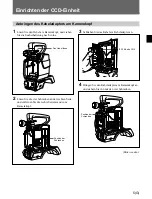
Page 5: ...とがあります 部品の取り付けは正しく行う 本機に以下の部品を取り付けるときは このインストレーションマニュアル の該当するページをよく読んだうえ 確実に取り付けてください 取り付け 方法を誤ると機器が落下し けがをすることがあります レンズ 9 J ページ 三脚 10 J ページ ケーブルアダプターをカメラ本体に取り付けるときは電源を遮 断する ケーブルアダプターをカメラに取り付けるときは カメラのPOWERスイッ チをOFFにするだけでなく トライアックスケーブルまたはDC IN端子等 に接続されたケーブルを取り外してください 電源が接続されたままでケー ブルアダプターの取り付けや取り外しを行うと 火災や故障の原因となるこ とがあります 強制 強制 ...

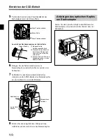
Page 6: ...ー 29ピン ケーブル 三脚アダプターで構成され レンズをカメ ラヘッ ドから離 れた所に設置する ことができます 本機はアスペク ト比16 9のワイ ド画面に対応していますが 付属の 4 3 16 9切り換え基板をカメ ラヘッ ドに取り付ける と 16 9のアスペ ク ト比を4 3に変換でき るよ う になり ます OHB T450WSはIT Interline Transfer 方式のCCDを採用して います 使用例 カメラ オプティカルヘッド ケーブル ケーブルアダプター 三脚アダプター レンズ OHB T450WS S Power HAD ...

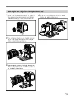
Page 7: ... 16 ND 雪景色 高い山 海辺など 澄み切って明るい景色 2 レンズマウントレバー レンズ 別売り をレンズマウ ン ト に固定します 3 レンズマウント レンズ 別売り を取り付けます 4 レンズマウントキャップ レンズを取り付けていないと きは このキャ ップをはめ込んでおき ま す レンズを取り付ける と きは レンズマウン ト レバーを反時計方向 に回して 外します 1 FILTERつまみ 2 レンズマウントレバー 3 レンズマウント 4 レンズマウントキャップ 5 CAM BODY端子 6 LENS端子 5 CAM BODY カメラヘッド接続 端子 29ピン 付属のケーブルでケーブルアダプターのOPT HEAD端子と接続 します 6 LENS レンズ 端子 12ピン レンズのケーブルを接続します この端子を介して カメ ラヘッ ドか ら レンズの機能をコン ト ロールする こ...

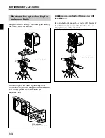
Page 8: ...6 J OPT HEAD CAM LENS 8 OPT HEAD端子 7 カメラレンズ ケーブル 各部の名称と働き ケーブルアダプター 7 カメラレンズケーブル カメ ラヘッ ドのLENS端子に接続します 8 OPT HEAD オプティカルヘッド接続 端子 29ピン 付属のケーブルで オプティ カルヘッ ドのCAM BODY端子と接続 します ...

Page 9: ...ーに接続する 4 ケーブルに無理な力がかからないよ う に注意しながら ケーブ ルアダプターをカメ ラヘッ ドに取り付け アダプターの4本のネ ジで固定する 使いかた ケーブルアダプターをカメラヘッドに取り付ける 1 カメ ラヘッ ドのレバーをゆるめ ビューフ ァイ ンダーの取り付け 部を前に出す 2 カメ ラヘッ ドの右側板のネジ4本をゆるめ 側板を外す レバー ネジ位置 ネジ位置 続く CAMHEAD CAMLENS IF 708基板のCN5 ...

Page 10: ...固 定する 6 側板を元どおりに取り付け 4本のネジで固定する 7 カメ ラ レンズケーブルをカメ ラヘッ ドのLENS端子に接続する ケーブルはケーブルク ラ ンプで固定する 8 付属のフ ィ ルターポジシ ョ ンラベルを カメ ラヘッ ドの右側板に 取り付ける ケ ー ブ ル クランプ LENS端子へ フ ィ ル タ ー ポ ジ シ ョ ン ラベル 使いかた オプティカルヘッドを三脚アダプターに 取り付ける オプティ カルヘッ ドを三脚アダプターのフ レームに取り付け 4本の ネジで固定します 青帯 24ピンフラットケーブル 20ピンフラットケーブル 中継基板 OPT HEAD CAM LENS S Power HAD CAMHEAD CAMLENS ...

Page 11: ...方向いっぱいに 回し マウン ト キャ ップを外す 2 レンズマウン ト上部中央の凹部にレンズのセンターピンを合わ せ レンズをマウン ト部に差し込む 3 レンズを支えながらマウ ン ト レバーを時計方向いっぱいに回し 固定する 4 レンズケーブルをオプティ カルヘッ ドのLENS端子に接続す る オプティカルヘッドにレンズを取り付ける S Power HAD S Power HAD S Power HAD S LENS CAM BODY S Power HAD ...

Page 12: ...付ける オプティ カルヘッ ドを取り付けた三脚アダプターを 下図のよ う に三 脚に取り付けます 使用する レンズによって重心の位置が変わり ます フ レームの位置 をずらせてバランスをとってく ださい フレームだけで三脚に取り付けるには 三脚アダプターの台からフ レームを外し フ レームだけで三脚に取 り付ける こ と もできます 雲台 雲台 六 角 レ ン チ で しっかり締める S Power HAD S フレーム S Power HAD S ...

Page 13: ... ドとケーブルアダプターは 必ずシ リ アル番号が 同じものを組み合わせてご使用く ださい オプティ カルヘッ ドとケーブルアダプターを接続するケーブルは OHB T450WSに付属の29ピンケーブルを使用してく ださい オプティカルヘッド 29ピンケーブル ケーブルアダプターを取り付けた カメラヘッド CAM BODY 端子へ OPT HEAD 端子へ S Power HAD CAM BODY LENS OPT HEAD CAM LENS ...

Page 14: ...着すると BVP 550側のセ ッ ト アップメニューを使用して下記の設定を変更す る こ とにより 36 dBまで選択可能になり ます MSU RCPから も選 択が可能です 設定のしかたについては BVP 550に付属のメ ンテナンスマニュアルを ご覧く ださい MENU System Config PAGE Others2 W Gain Off On 4 3 16 9切り換え基板をカメラヘッドに 取り付ける OHB T450WSに付属の4 3 16 9切り換え基板をカメ ラに取り付け る と アスペク ト比を16 9から4 3に変換する機能を使用する こ とが できます 1 カメ ラヘッ ドの左側板のネジ4本をゆるめて 側板を外す 2 中央の基板をネジ2本をゆるめて外す ネジ ネジ ネジ 使いかた ...

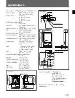
Page 15: ...0 lx 3200 89 9 反射 最低被写体照度 約1 lx F1 4 レンズ 36dB S N 63 dB 標準 水平解像度 700TV本 垂直解像度 400TV本 450TV本 EVS時 幾何学ひずみ 測定限界値以下 レンズを除く シャッタースピード 1 100 1 125 1 250 1 500 1 1000 1 2000 ゲイン 3 dB 0 dB 3 dB 6 dB 9 dB 12 dB 18 dB 24 dB 30 dB 36 dB CLS 1 60 1 1 7000 消費電力 カメラに組み込み時 17 5 W DC入力 10 5 V 17 V 動作温度 20 45 保存温度 20 50 質量 0 75 kg 外形寸法 図参照 単位 mm 3 8インチ三脚ネジ 1 4インチ三脚ネジ 4 M4 93 33 46 5 93 32 5 65 15 6 75 41 46 5 44 1...

Page 16: ......

Page 17: ... limits are designed to provide reasonable protection against harmful interference when the equipment is operated in a commercial environment This equipment generates uses and can radiate radio frequency energy and if not installed and used in accordance with the instruction manual may cause harmful interference to radio communications Operation of this equipment in a residential area is likely to...

Page 18: ... unit can be installed at a place remote from the camera head The unit is designed for shooting in 16 9 wide screen For 4 3 normal screen attach the supplied 4 3 16 9 selector board to the camera head The OHB T450WS T450WSP unit uses IT Interline Transfer CCD Example of Usage Overview Lens Optical head Cable Camera head Tripod adaptor Cable adaptor OHB T450WS T450WSP S Power HAD ...

Page 19: ...d to the lens mount 3 Lens mount Attach a lens not supplied to this mount 4 Lens mount cap Keep this cap on when no lens is mounted Remove this cap by turning the lens fixing lever counterclockwise to mount a lens Functions of Parts and Controls 5 CAM BODY camera head connector 29 pin Used to connect to the OPT HEAD connector on the cable adaptor using the supplied cable 6 LENS connector 12 pin Us...

Page 20: ...Used to connect to the LENS connector on the camera head 8 OPT HEAD optical head connector 29 pin Used to connect to the CAM BODY connector on the optical head using the supplied cable 8 OPT HEAD connector 7 Camera lens cable Functions of Parts and Controls ...

Page 21: ... right side panel from the camera head Setting Up the CCD Unit 3 Connect the normal cable to the cable adaptor 4 Attach the cable adaptor to the camera head and secure it with the four mounting screws of the adaptor Attaching a Cable Adaptor to a Camera Head Loosen this lever Screw positions IF 708 board CN5 Screw positions Continued CAMHEAD CAMLENS ...

Page 22: ...el to the right side panel of the camera head Attaching the Optical Head to a Tripod Adaptor Attach the optical head to the frame of a tripod adaptor and secure the head with the four screws S Power HAD S Relay board 24 pin flat cable 20 pin flat cable Blue strip Cable clamp Filter position label to the LENS connector OPT HEAD CAM LENS To connect the flat cable to the relay board 1 Lift up the con...

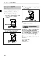
Page 23: ...d of the lens barrel with the center slot in the lens mount and insert the lens into the lens mount 3 While holding the lens in place push the lens fixing lever clockwise to secure the lens 4 Connect the lens cable to the LENS connector on the optical head Mounting a Lens to an Optical Head S Power HAD S S Power HAD S Power HAD Power HAD S LENS CAM BODY ...

Page 24: ...ripod adaptor Mounting the Optical Head on a Tripod Attach the tripod adaptor with the optical head mounted to the tripod as shown below The center of gravity with respect to the tripod adaptor differs according to the lens you are using Adjust the balance by shifting the position of the frame on the adaptor Camera mount S Power HAD S Tighten with a hexagonal wrench Camera mount S Power HAD S ...

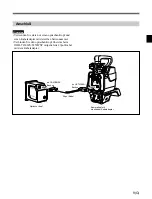
Page 25: ...e serial number Use the 29 pin cable supplied with the OHB T450WS T450WSP to connect the optical head and the cable adaptor to the CAM BODY connector 29 pin cable to the OPT HEAD connector Optical head Camera head with the cable adaptor attached S Power HAD CAM BODY LENS OPT HEAD CAM LENS ...

Page 26: ...ing the setup menu on the BVP 550 550P For details refer to the maintenance manual supplied with the BVP 550 550P MENU System Config PAGE Others2 W Gain Off On Attaching a 4 3 16 9 Selector Board to the Camera Head A 4 3 16 9 conversion function can be used by attaching the 4 3 16 9 selector board supplied with the OHB T450WS T450WSP to the camera head 1 Loosen four screws on the left side of the ...

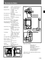
Page 27: ... when attached to the camera 17 5 W DC input 10 5 V to 17 V Operating temperature 20 C to 45 C 4 F to 113 F Storage temperature 20 C to 50 C 4 F to 122 F Mass 0 75 kg 1 lb 9 oz Dimensions See the figure below Unit mm inches Accessories supplied Cable adaptor 1 29 pin cable 1 Filter position label 1 Tripod adaptor 1 4 3 16 9 selector board 1 Installation manual 1 Maintenance manual 1 Design and spe...

Page 28: ......

Page 29: ...Überblick 2 G Verwendungsbeispiel 2 G Funktion der Bedienungselemente 3 G Optischer Kopf 3 G Kabeladapter 4 G Einrichten der CCD Einheit 5 G Anbringen des Kabeladapters am Kamerakopf 5 G Anbringen des optischen Kopfes am Stativadapter 6 G Anbringen des Objektivs am optischen Kopf 7 G Montieren des optischen Kopfes auf einem Stativ 8 G Anschluß 9 G Einsetzen der 4 3 16 9 Formatwahlkarte in den Kame...

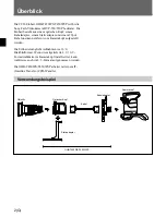
Page 30: ... Kamerakopf aufgestellt werden Die Einheit ermöglicht Aufnahmen im 16 9 Breitbildformat Wenn die mitgelieferte 4 3 16 9 Formatwahlkarte im Kamerakopf installiert ist kann wahlweise auch im 4 3 Format aufgenommen werden Die OHB T450WS T450WSP arbeitet mit einem IT Interline Transfer CCD Wandler Verwendungsbeispiel Überblick Objektiv Optischer Kopf Kabel Kamerakopf Stativadapter Kabeladapter OHB T45...

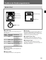
Page 31: ...ektivanschluß 3 Objektivanschluß Zum Anbringen des Objektivs nicht mitgeliefert Funktion der Bedienungselemente 4 Schutzkappe Setzen Sie die Kappe auf den Objektivanschluß wenn das Objektiv nicht angebracht wird Nehmen Sie vor Anbringen des Objektivs die Kappe ab indem Sie den Fixierhebel im Gegenuhrzeigersinn drehen 5 CAM BODY Buchse 29pol Diese Buchse wird über das mitgelieferte Kabel mit der OP...

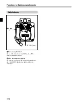
Page 32: ...es Kabel dient zum Anschluß an die LENS Buchse des Kamerakopfes 8 OPT HEAD Buchse 29pol Diese Buchse wird über das mitgelieferte Kabel mit der CAM BODY Buchse des optischen Kopfes verbunden 8 OPT HEAD Buchse 7 Kamera objektivkabel Funktion der Bedienungselemente ...

Page 33: ...Sie die rechte Seitenwand vom Kamerakopf Einrichten der CCD Einheit 3 Schließen Sie das Kabel am Kabeladapter an 4 Bringen Sie den Kabeladapter am Kamerakopf an und sichern Sie ihn mit den vier Schrauben Anbringen des Kabeladapters am Kamerakopf Den Hebel lösen Position der Schrauben Position der Schrauben Bitte wenden CAMHEAD CAMLENS IF 708 Karte CN5 ...

Page 34: ...uf die rechte Seite des Kamerakopfes Anbringen des optischen Kopfes am Stativadapter Setzen Sie den optischen Kopf in den Rahmen des Stativadapters ein und sichern Sie ihn mit den vier Schrauben S Power HAD S Kabelklemme Filterpositions Aufkleber An die LENS Buchse OPT HEAD CAM LENS Anschluß des Flachbandkabels an der Relais Platte 1 Klappen Sie die Verbindungsstifte hoch 2 Stecken Sie das Kabel m...

Page 35: ...ß an daß der Zentrierstift auf die Aussparung im Objektivanschluß ausgerichtet ist 3 Halten Sie das Objektiv in Position und drücken Sie den Objektivfixierhebel im Uhrzeigersinn um das Objektiv zu befestigen 4 Schließen Sie das Objektivkabel an der LENS Buchse des optischen Kopfes an Anbringen des Objektivs am optischen Kopf S Power HAD S S Power HAD S Power HAD Power HAD S LENS CAM BODY ...

Page 36: ...t vom verwendeten Objektiv ab Bringen Sie den Rahmen so an der Trägerplatte an daß die Einheit gut ausbalanciert ist Anbringen des optischen Kopfes nur mit dem Rahmen Der optische Kopf kann auch nur mit dem Rahmen auf einem Stativ montiert werden Nehmen Sie dazu die Trägerplatte vom Stativadapter ab Kamerahalteplatte S Power HAD S Kamerahalteplatte S Power HAD S Mit Sechskant Steckschlüssel festzi...

Page 37: ...r mit derselben Seriennummer Verbinden Sie den optischen Kopf über das beim OHB T450WS T450WSP mitgelieferte 29pol Kabel mit dem Kabeladapter an CAM BODY Buchse 29pol Kabel an OPT HEAD Buchse Optischer Kopf Kamerakopf mit montiertem Kabeladapter S Power HAD CAM BODY LENS OPT HEAD CAM LENS ...

Page 38: ...VP 550 550P eine Verstärkung von 36 dB gewählt werden Einzelheiten entnehmen Sie bitte der Wartungsanleitung der BVP 550 550P MENU System Config PAGE Others2 W Gain Off On Einsetzen der 4 3 16 9 Formatwahlkarte in den Kamerakopf Wenn die beim OHB T450WS OHB T450WSP mitgelieferte 4 3 16 9 Formatwahlkarte im Kamerakopf eingesetzt ist kann zwischen dem Bildformat 4 3 und 16 9 gewählt werden 1 Lösen S...

Page 39: ...1 500 1 1000 1 2000 Verstärkung 3 dB 0 dB 3 dB 6 dB 9 dB 12 dB 18 dB 24 dB 30 dB 36 dB CLS NTSC 1 60 1 bis 1 7000 PAL 1 50 2 bis 1 9000 Leistungsaufnahme bei Anbringung an Kamera 17 5 W Stromversorgung 10 5 V bis 17 V Betriebstemperaturbereich 20 C bis 45 C Lagertemperaturbereich 20 C bis 50 C Gewicht 0 75 kg Abmessungen Siehe Abbildung unten Einheit mm Mitgeliefertes Zubehör Kameraadapter 1 29pol...

Page 40: ......

Page 41: ...des acquéreurs de l équipement décrit dans ce manuel Sony Corporation interdit formellement la copie de quelque partie que ce soit de ce manuel ou son emploi pour tout autre but que des opérations ou entretiens de l équipement à moins d une permission écrite de Sony Corporation Das in dieser Anleitung enthaltene Material besteht aus Informationen die Eigentum der Sony Corporation sind und ausschli...

Page 42: ...Sony Corporation Broadcasting Professional Systems Company Printed in Japan 1998 06 13 1998 OHB T450WS T450WSP J UC CE 和 英 独 3 864 358 02 1 ...

Reviews: