background image

NSZ-GS7/NSZ-GX70 16

SECTION 2 - DISASSEMBLY/PART NUMBER INFORMATION

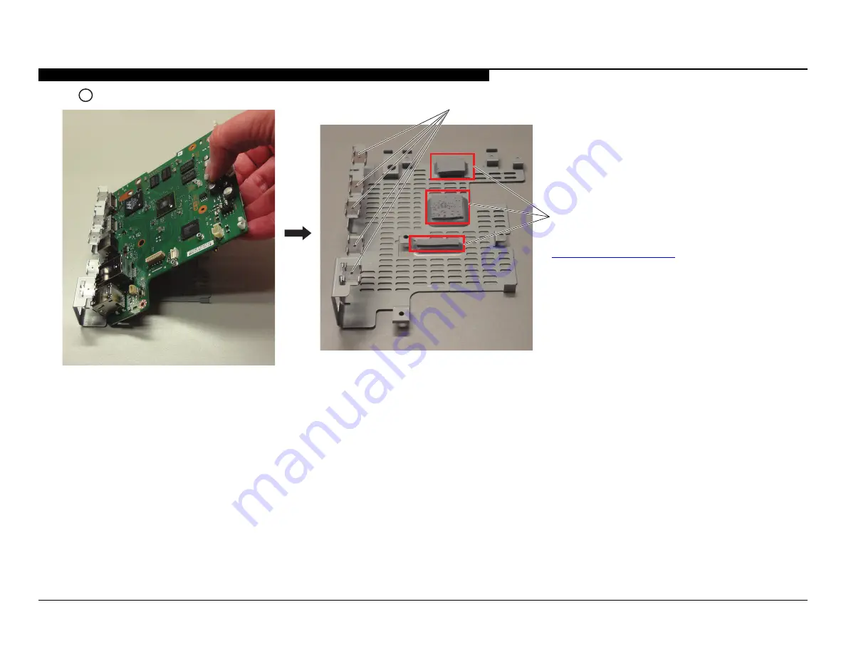
C   Tilt and lift up MS Board to detach from Bottom Shield 

Ensure the EMI springs are still

attached to the shield 

CAUTION: The Thermal Pads must be replaced before 

reattaching the MS Board to the Bottom Shield.

(For Thermal Pad Part Number information, refer to 

“Exploded View” on page 21.

)

Summary of Contents for NSZ-GX70

Page 1: ...Version Date Subject 1 0 6 8 2012 Original Manual Release Date 2 0 6 21 2012 Reissue entire manual 3 0 7 13 2012 Corrected screw type for Screw M2 0 x L2 5 J Replaced page 13 21 Added caution and part number information for Thermal Pads Replaced pages 15 16 21 ORIGINAL MANUAL ISSUE DATE 6 2012 HISTORY INFORMATION FOR THE FOLLOWING MANUAL ...

Page 2: ...SERVICE MANUAL Network Media Player 9 883 890 53 SelfDiagnosis Supported model LEVEL 3 CONFIDENTIAL NSZ GS7 GX70 NSG MR5D MR5E MR5F MR5U NSZ GS7 NSG MR5U ...

Page 3: ...MODEL LIST 9 883 890 53 MODEL DESTINATION MODEL DESTINATION NSZ GS7 US NSZ GS7 CANADA NSZ GS7 AEP NSZ GS7 BRAZIL NSZ GS7 MEXICO NSZ GS7 UK NSZ GX70 US ...

Page 4: ...ble Wire Dressing 18 Exploded View 21 Cables 22 Connectors 22 Fuse 22 Accessories and Packing 23 Remote Commander 23 Section 3 Updates and Adjustments 24 Refurbishing the Network Media Player 24 Updating the Software 24 Re initializing to Factory Mode 25 Completing Basic Checks 28 Resetting the Remote Commander 28 Resetting the Original Remote Commander 29 Resetting a New Remote Commander 29 Optio...

Page 5: ...1 of 18 46 MS Board Schematic 12 of 18 47 MS Board Schematic 13 of 18 48 MS Board Schematic 14 of 18 49 MS Board Schematic 15 of 18 50 MS Board Schematic 16 of 18 51 MS Board Schematic 17 of 18 52 MS Board Schematic 18 of 18 53 UR Board Schematic 56 Appendix A Encryption Key Components A 1 ...

Page 6: ...d in this manual Follow these procedures whenever critical components are replaced or improper operation is suspected NOTE Do not modify the original design without obtaining written permission from the manufacturer or you will void the original parts and labor warranty ATTENTION Ces instructions de service sont à l usage du personnel de service qualifié seulement Pour prévenir le risque de choc é...

Page 7: ...ring the Power Supply Board and is prohibited 9 Check the B voltage to see it is at the values specified LEAKAGE TEST The AC leakage from any exposed metal part to earth ground and from all exposed metal parts to any exposed metal part having a return to chassis must not exceed 0 5 mA 500 microamperes Leakage current can be measured by any one of three methods 1 A commercial leakage tester Follow ...

Page 8: ...ations to prevent outsiders from intercepting communications or intruding into your wireless network WEP is a legacy security technology that enables older devices which do not support TKIP AES to be connected WPA PSK TKIP WPA2 PSK TKIP TKIP is a security technology developed to correct for the deficiencies of WEP TKIP assures a higher security level than WEP WPA PSK AES WPA2 PSK AES AES is a secu...

Page 9: ...NSZ GS7 NSZ GX70 1 SECTION 1 TROUBLESHOOTING CONNECTION CHECK STB NSZ GS7 TV HDMI input HDMI output AV Receiver Optical ...

Page 10: ...D blinking END See No Power See Power LED Blinking Is the network connection OK See Network Error No Yes Yes Yes No No Is the USB functioning OK See USB Error No Is Remote Commander working properly See Remote Error No Yes Is the Picture and Sound OK See No Picture No Sound No Is the IR Blaster OK See IR Blaster Error No Yes Yes Yes ...

Page 11: ...70 3 SECTION 1 TROUBLESHOOTING NO POWER No Power Wire Harness G Board MS Board Replace Switching Regulator G Board NG NG Symptom improvement Swap wire harness between the MS Board and the G Board Symptom improvement ...

Page 12: ...re harness between the MS Board and the G Board Symptom improvement Symptom improvement 7 BLINKS TEMPERATURE ERROR 7 Blinks MS Board Yes Are the settings OK Temperature Ventilation etc Set to another location etc NG Check assembly of MS Board heat sink thermal pads shield screws Assembly Error Replace Switching Regulator G Board G Board NG No Symptom improvement Symptom improvement ...

Page 13: ...TROUBLESHOOTING 10 BLINKS GOOGLE TV BOOT UP ERROR 10 Blinks Use Service Menu to Update Software Software Symptom improvement MS Board NG 11 BLINKS IR BLASTER ERROR 11 Blinks UR Board MS Board Replace UR Board NG Symptom improvement ...

Page 14: ... OUTPUT HDMI Cable HDMI Cable No MS Board Symptom improvement No Replace FUSE F1900 1 576 863 31 Yes FUSE F1900 is located on MS Board B side FUSE F1900 open FUSE F1900 is located on the B side of the MS Board FOR FUSE DESCRIPTION AND PART NUMBER INFORMATION REFER TO FUSE ON PAGE 22 ...

Page 15: ...HOOTING NO SOUND No Sound Optical Sound is OK Audio Output priority setting is SPDIF Change to SPDIF Cable No No Yes SPDIF Cable HDMI Sound is OK Audio Output priority setting is HDMI Yes Change to HDMI Cable No Yes HDMI Cable MS Board No ...

Page 16: ...place the remote and replace the batteries Remote Commander Check connection of antennas to Wireless Module Connection Replace the batteries Battery power is low NG Symptom improvement Symptom improvement Symptom improvement Symptom improvement Symptom improvement NG Complete Pairing the Network Media Player to a Remote Bottom Cover Assembly Replace the Bottom Cover Assembly Symptom improvement NG...

Page 17: ... Board NG INTERNAL WIRELESS NETWORK ERROR Wireless Network Error Wireless Module Use Service Mode menu options to Update the Software and perform a Factory Reset Settings customer environment NG Symptom Improvement NG Symptom Improvement NG Assembly Symptom Improvement Replace Wireless Module Check connections of antennas to Wireless Module MS board NG Replace the Bottom Cover Assembly Bottom Cove...

Page 18: ...NSZ GX70 10 SECTION 1 TROUBLESHOOTING USB ERROR USB Error Use Service Mode menu options to Update the Software and perform a Factory Reset Network Media Player Application Error Symptom improvement MS Board NG ...

Page 19: ...Test Package Remote Commander with Network Media Player Pair a Remote Commander with the Network Media Player Complete repair of Network Media Player Update Software Re initialize to Factory Mode Complete Basic Test Reset the Remote Commander YES Reset the Remote Commander by completing a Factory reset and un pair Remote Control RESETTING THE REMOTE COMMANDER FOR COMPLETE INSTRUCTIONS REFER TO SEC...

Page 20: ...down on its Top Cover and remove 2 screws from Bottom Cover SCREW M2 0 x L5 Qty 2 B Gently place the network media player right side up then slide Top Cover towards backside of the network media player and lift up to detach from Bottom Cover SECTION 2 DISASSEMBLY PART NUMBER INFORMATION ...

Page 21: ...le to detach from MS Board C Remove the Wi Fi cables from the MS Board and the G Board Assembly Switch Regulator clips CAUTION DO NOT pull on the antenna cables at the solder joint when removing them from the clips Refer to Wire Dressing on page 17 when reinserting the antenna cables back into the clips SCREW M2 0 x L2 5 J Qty 2 Screw Locator is covered by label NOTE The label on the Wi Fi Board m...

Page 22: ... BOARD REMOVAL A Remove 1 screw and lift up Switching Regulator to detach from Bottom Cover SCREW M2 0 x L5 Qty 1 B Release 5 clips and lift up G Board Safety Top to detach from G Board Safety Bottom Release clips Qty 5 G Board Safety Bottom G Board Safety Top Switching Regulator G Board ...

Page 23: ...g the MS Board A Remove 4 screws and lift up Heat sink to detach from MS Board SCREW M2 0 x L10 Qty 4 Check the bottom of the Heat Sink if the Thermal Pad is not on the MS Board CAUTION The Thermal Pad must be replaced before reattaching the Heat Sink to the MS Board B Remove 2 screws and lift up MS Board to detach from Bottom Cover SCREW M2 0 x L5 Qty 2 For Thermal Pad Part Number information ref...

Page 24: ...and lift up MS Board to detach from Bottom Shield Ensure the EMI springs are still attached to the shield CAUTION The Thermal Pads must be replaced before reattaching the MS Board to the Bottom Shield For Thermal Pad Part Number information refer to Exploded View on page 21 ...

Page 25: ...NSZ GS7 NSZ GX70 17 SECTION 2 DISASSEMBLY PART NUMBER INFORMATION WIRE DRESSING OVERALL WIRE DRESSING OVERALL WIRE DRESSING ...

Page 26: ...2 DISASSEMBLY PART NUMBER INFORMATION ANTENNA CABLE WIRE DRESSING Use the directions on the other side of the following pages to ensure that the antenna cables are properly inserted back into the clips ANTENNA CABLES WIRE DRESSING ...

Page 27: ...enna cable from the AUX antenna ensure the cable is 1 Routed down from the AUX antenna 2 Routed 4 to 5 mm away from the Main antenna board 3 Inserted into the clips then connected to the Wi Fi Board CAUTION When routing the Black antenna cable from the Main antenna ensure the cable is 4 Routed down from the Main antenna 5 Under the Switching Regulator G Board 6 Inserted into the clip then connecte...

Page 28: ...ASSEMBLY PART NUMBER INFORMATION CAUTION When routing the White antenna cable from the BT antenna ensure the cable is 1 Routed down from the BT antenna 2 Inserted into the clip then connected to the Wi Fi Board 1 2 WHITE ANTENNA CABLE ...

Page 29: ...M THE BOTTOM SHIELD 10 1 474 387 11 SWITCHING REGULATOR ABBREVIATIONS US USA Puerto Rico CND Canada AEP 1 Germany AEP 2 France AEP 3 All Other Europe BRZ Brazil MX Mexico UK United Kingdom EXPLODED VIEW NOTE Lescomposantsidentifiesperuntrameet une marque sont critiques pour la securite Ne les remplacer que par une piece portant le numero specifie NOTE The components identified by shading and mark ...

Page 30: ... 071 0001 1675 REF NO PART NO DESCRIPTION REMARK 56 1 576 863 31 F1900 MICRO FUSE LINK 1608 TYPE CABLES CONNECTORS 51 REF NO PART NO DESCRIPTION REMARK 52 1 842 680 11 HDMI CONNECTOR 53 9 885 168 31 PHONO JACK 2N 000300G FKG0 54 9 885 168 30 LAN CONNECTOR 1N 000800C FKG0 55 9 885 170 82 USB CONNECTOR 2N 000800E MKG0 52 53 54 55 FUSE ...

Page 31: ... CORD EURO ALLAEP 9 885 170 21 AC CORD BRZ BRZ 9 885 170 20 AC CORD UK UK 1 835 072 11 CORD SET POWER US CND MX 1 759 586 41 IR BLASTER CABLE 9 885 170 24 HDMI CABLE 015 0001 1879 NSZ GX70 US REF NO PART NO DESCRIPTION REMARK 4 421 774 11 REFERENCE GUIDE US CND 4 421 774 21 REFERENCE GUIDE CND 4 421 774 31 REFERENCE GUIDE MX 4 421 774 41 REFERENCE GUIDE BRZ 4 421 777 11 REFERENCE GUIDE UK 4 421 77...

Page 32: ...SB input slot on the back of the Network Media Player USB Input 3 Connect the USB keyboard to the other USB input slot 4 Disconnect the AC Power Cord from the Network Media Player 5 Connect the Network Media Player to the TV using the HDMI cable between the HDMI Out and HDMI In ports respectively 6 Proceed to Installing the Software INSTALLING THE SOFTWARE 1 Power on the Network Media Player by pl...

Page 33: ...tarted The Network Media Player will start the update process and a progress bar displays During the update the LED on the front of the Network Media Player will blink 7 When the update is complete the Android System Recovery screen displays 8 Remove the USB memory drive from the Network Media Player 9 Proceed to Re initializing to Factory Mode RE INITIALIZING TO FACTORY MODE After completing the ...

Page 34: ...e USB keyboard move down the list and highlight Full Initialization Service Mode Sat May 5 18 12 47 2012 Measure WLAN RSSI Show System Info Show Safety Shutdown Registers Reset Safety Shutdown Registers Log Copy Full Ini aliza on 14 Press ENTER Service Mode Sat May 5 18 12 47 2012 Full Ini aliza on 1 Yes 2 No 15 Using the arrow keys on the USB keyboard move down the list and highlight Yes Service ...

Page 35: ...sion that is installed 19 Using the arrow keys on the USB keyboard move down the list and highlight Service mode Android system recovery 2end sony 927 Use arrow keys to highlight enter to select Reboot system now CTRL R Factory reset and keep Remot Control paired CTRL W Factory reset and un pair Remote Control So wared update via USB update update zip CTRL S Service mode CTRL A Power off 20 Press ...

Page 36: ...6 To exit Service Mode turn the Network Media Player OFF by disconnecting the AC Power Cord 27 Proceed to Completing Basic Checks COMPLETING BASIC CHECKS Perform the following test to be sure the Network Media Player is functioning properly Complete before shipping Test LAN USB HDMI Input HDMI Output and SPDIF Test Wi Fi Test Bluetooth Use Remote Commander Test IR Blaster test both internal and ex...

Page 37: ...used to verify the Remote Commander pairs with the Network Media Player 30 Turn the Network Media Player ON 31 Using a thin sharp object such as the point of a pen or small screw driver press and hold the Connect button on the bottom of the Network Media Player 32 Follow the instructions on the screen to complete the pairing 33 Turn OFF the Network Media Player 34 Disconnect the AC Power Cord from...

Page 38: ...elect Reboot system now CTRL R Factory reset and keep Remot Control paired CTRL W Factory reset and un pair Remote Control So wared update via USB update update zip CTRL S Service mode CTRL A Power off 40 Press ENTER The screen displays log messages during the Factory Reset process 41 When the reset is complete the Android system recovery screen displays Android system recovery 2end sony 927 Use a...

Page 39: ...for 10 seconds 4 Release the Connect button Wait 10 to 15 seconds until the Android System Recovery screen displays Android system recovery 2end sony 927 Use arrow keys to highlight enter to select Reboot system now CTRL R Factory reset and keep Remot Control paired CTRL W Factory reset and un pair Remote Control So wared update via USB update update zip CTRL S Service mode CTRL A Power off 5 Usin...

Page 40: ...arrow keys on the USB keyboard move down the list and highlight the option you want to select a To view the self diagnostics information select Show Safety Shutdown Registers b To clear the self diagnostics information select Reset Safety Shutdown Registers c To create a copy of the log file select Log Copy 9 Press ENTER 10 Follow any on screen instructions 11 To return to the Service Mode menu pr...

Page 41: ...sible a action rapide Doit etre remplace par une fusible de meme yaleur comme maque NOTE The components identified by a red outline and a mark contain confidential information Specific instructions must be adhered to whenever these components are repaired and or replaced See Appendix A Encryption Key Components in the back of this manual COIL LF 8L MICRO INDUCTOR CAPACITOR TA TANTALUM PS STYROL PP...

Page 42: ...VI0 15 0 USB1 SD0 HDMI out IR blaster IRB uC SPDIF SPDIFO Digital Audio Out WiFi 11n BT 1x1 Adapter Marvell SDIO 1GB NAND FLASH SATA conector USB 2 0 USB 2 0 Power LED Indicator CONNECT SWITCH HPD IR Receiver UR board Front IR blaster Jack DVI CLK HS VS FID DVI CLK HS VS FID SM_HDMI_HPD SM_GPIO 7 HPD MS board STM32F100C6T6BTR BOOT JIG SPI1 8GB eMMC CEC CEC Power switch Power switch OC OC EN EN 5V_...

Page 43: ...PONENT 2 F1 CX1 R2 R1 C4 D7 1 2 3 4 5 6 7 8 IC1 Q1 C11 CY1 SG B D6 C10 L N R19 D9 R20 2 1 4 3 NF1 C6 C9 R8 R9 R14 R6 R5 R13 R12 R11 R7 C7 C2 C1 C5 R3 R4 C3 C12 GND 3 4 1 2 T1 D1 D4 D2 D3 R23 Z1 2 1 J1 JUMP R17 ZD1 R10 D5 C8 R15 D8 R18 R16 R21 R22 A B C13 2 1 J2 JUMP GND GND TP1 TP2 TP3 TP4 TP5 TP6 TP7 TP8 TP9 TP10 TP11 TP12 TP13 TP14 TP15 TP16 TP18 TP20 TP21 TP22 TP23 TP24 TP25 TP26 TP27 TP28 1 2 ...

Page 44: ...CTSn Y12 SM_URT0_RTSn AA12 SM_URT1_RXD AC12 SM_URT1_TXD AB12 SM_ADCI 0 AD2 SM_ADCI 1 AC2 SM_ADCI 2 AB4 SM_ADCI 3 AA4 SM__0p9V_ENn AE2 SM_ISET AB1 SM_GPIO 0 AA7 SM_GPIO 1 AB7 SM_GPIO 2 AA8 SM_GPIO 3 AC8 SM_HDMI_CEC AC10 SM_HDMI_HPD AD10 SM_HDMIRX_PWR5V AE10 SM_SPI2_SS0n AB8 SM_SPI2_SS1n AA9 SM_SPI2_SS2n AC9 SM_SPI2_SS3n AD9 SM_SPI2_SCLK Y10 SM_SPI2_SDO AB10 SM_SPI2_SDI AA10 FE_TXP Y4 FE_TXN Y3 FE_R...

Page 45: ...D_1 9 RXD 10 TXD 11 GND_2 12 SPI_SCLK 13 GND_3 14 SPI_SDO 15 GND_4 16 SPI_SDI 17 SPI_FLASH_BSRC0 18 SPI1_SS0 19 SPI_FLASH_BSRC1 20 GND_5 21 GND_6 22 R3032 0_J R3011 4 7K_J C3007 NC_2200P_50V_K R3026 NC_10K_J CL3008 1 1 JL3002 1 1 R3019 33_J JL3013 1 1 R3009 47K_J R3008 NC_4 7K_J CL3011 1 1 R3029 NC_0_J JL3003 1 1 R3007 4 7K_J R3016 100_J C3002 NC_0 01U_16V_K CL3003 1 1 R3003 0_J IC3000 NC_FLASH_SO...

Page 46: ... 6 C10 DVIO 7 F11 DVIO 8 B9 DVIO 9 E10 DVIO 10 C9 DVIO 11 E9 DVIO 12 C8 DVIO 13 D8 DVIO 14 E8 DVIO 15 F10 DVO_CLK C6 DVO_HS D7 DVO_VS G22 4 PWM 2 D6 DVO_FID E7 HDMI_TCKP R3 HDMI_TCKN R4 HDMI_TD0P R2 HDMI_TD0N R1 HDMI_TD1P T2 HDMI_TD1N T1 HDMI_TD2P U3 HDMI_TD2N U2 HDMI_HEACN P3 HDMI_HEACP P4 VDAC1P F3 VDAC2P F2 VDAC3P F4 VDAC4P F1 VDAC_REXT E1 LVDS0_TCKP K1 LVDS0_TCKN K2 LVDS0_TD4P J3 LVDS0_TD4N J4...

Page 47: ...H23 M0_A 1 J21 M0_A 2 J23 M0_A 3 H22 M0_A 4 K25 M0_A 5 K21 M0_A 6 K22 M0_A 7 L23 M0_A 8 M22 M0_A 9 L25 M0_A 10 G21 M0_A 11 M23 M0_A 12 H21 M0_A 13 L22 M0_A 14 M21 M0_VREFD L21 M0_CAL M20 M0_DQSP 0 D14 M0_DQSN 0 D13 M0_DM 0 F12 M0_DQ 0 E12 M0_DQ 1 C12 M0_DQ 2 D12 M0_DQ 3 E13 M0_DQ 4 C14 M0_DQ 5 F14 M0_DQ 6 C15 M0_DQ 7 D15 M0_DQSP 1 A16 M0_DQSN 1 A15 M0_DM 1 F15 M0_DQ 8 E15 M0_DQ 9 B16 M0_DQ 10 C16 ...

Page 48: ...se refer to user manual TEST enable 1 enable scan or AC scan testes 0 enable ARM ICE JTAG connections SM_TEST_EN 1 for the following modes SM_JTAG_SEL 0 is scan enable SM_JTAG_SEL 1 is scan compression enable Engineering debug feature enable bonding option tie to VIO6 3 3V Fixed to enable debug features software_strap 4 software_strap 3 software_strap 2 software_strap 1 software_strap 0 nandV18Ena...

Page 49: ...7023 1000P_50V_K FB7000 470R_100MHZ_0603 C7075 0 1U_16V_K C7063 0 1U_16V_K C7097 10U_6 3V_K JL7001 1 1 C7074 0 01U_16V_K C7082 0 1U_16V_K R7001 NC_0_J R7000 0_J R7003 NC_4 7K_J C7078 0 01U_16V_K C7018 NC_1000P_50V_K C7028 1000P_50V_K R7009 NC_0_J FB7001 470R_100MHZ_0603 JL7002 1 1 JL7003 1 1 IC2001G 88DE3100Z1 BMR2C000_B0 VSS_1 A25 VSS_2 B6 VSS_3 B20 VSS_4 C23 VSS_5 D9 VSS_6 D17 VSS_7 D23 VSS_8 E4...

Page 50: ...6 1 1 R8053 NC_100K_J R8029 33_J R8042 10K_J CL8012 1 1 C8014 NC_1U_6 3V_K C8015 NC_100U_6 3V_M C8022 NC_100U_6 3V_M C8017 NC_2200P_50V_K IC8003B FLASH_TFBGA 169_8GB NC_18 A4 NC_19 A6 NC_20 A9 NC_21 A11 NC_22 B2 NC_23 B13 NC_24 D1 NC_25 D14 NC_26 H1 NC_27 H2 NC_28 H8 NC_29 H9 NC_30 H10 NC_32 H12 NC_33 H13 NC_31 H11 NC_34 H14 NC_35 J1 NC_36 J7 NC_37 J8 NC_38 J9 NC_39 J10 NC_40 J11 NC_41 J12 NC_42 J...

Page 51: ... D D GND D VBUS D GND CN9001 STACKED USB CONN_8P 1 2 3 4 5 6 7 8 12 11 9 10 C9017 0 1U_16V_K VD9005 R9019 47K_D C9020 47U_6 3V_K 1206_X6S L9001 90R 100MHZ_1 5R 3 2 1 4 R9022 0_J R9021 NC_4 7K_J R9018 10K_J C9028 0 01U_25V_K VD9011 VD9006 R9025 0_J R9017 47K_D VD9007 C9026 1000P_50V_K FB9004 120R 100MHZ_0603 C9041 NC_47U_6 3V_K 1206_X6S C9016 0 1U_16V_K C9025 1000P_50V_K C9023 NC_47U_6 3V_K 1206_X6...

Page 52: ...4 P2 5 TDI 25 P2 6 TMS 26 P2 7 TDO 27 R1067 NC_0_J R1032 NC_47_J C1033 NC_100pF_50V_J R1019 0_J R1007 NC_120_D C1007 0 1U_16V_K C1023 NC_33P_50V_J FB1000 470R_100MHZ_0603 R1042 47_J R1014 NC_10K_J SL1003 JL1007 1 1 SL1002 VD1000 NC_AVR M1608C270MTAAB_VR R1015 1K_J R1044 47_J C1025 NC_1000P_50V_K JL1000 1 1 B C E Q1000 NC_2SC5658FS6T2LR 1 3 2 C1005 10P_50V_J B C E Q1005 NC_2SC5658FS6T2LR 1 3 2 R106...

Page 53: ...CC_2 4 BG2_FE_RX_P 5 BG2_FE_RX_N 6 NC 7 GND 8 NPTH_1 11 NPTH_2 12 9 9 10 10 C1111 0 1U_16V_K C1120 0 1U_16V_K R1111 47K_J C1122 0 1U_16V_K R1127 NC_0_J C1102 10U_6 3V_K 0805_X6S X1100 32 768KHZ_3 6V VIO 1 NC_1 2 NC_2 3 NC_3 4 NC_4 5 GND 6 OUT 7 NC_5 8 NC_6 9 NC_7 10 NC_8 11 VCC 12 R1105 1K_J R1133 0_J C1121 NC_10U_6 3V_K 0805_X6S C1123 0 1U_16V_K R1101 49 9_D Q1103 NC_DRC3114E0L E 2 C 3 B 1 R1103 ...

Page 54: ...7 GND_2 8 Output_3 9 Output_4 10 Q1901 DRC3114E0L 2 E 3 C 1 B D1904 DB2730800L 1 2 CN1901 HDMI Sockect_19P TMDS_D2P 1 TMDS_GND_1 2 TMDS_D2N 3 TMDS_D1P 4 TMDS_GND_2 5 TMDS_D1N 6 TMDS_D0P 7 TMDS_GND_3 8 TMDS_D0N 9 TMDS_CLKP 10 TMDS_GND_4 11 TMDS_CLKN 12 CEC 13 NC 14 DDC_SCL 15 DDC_SDA 16 DDC_CEC_GND 17 5VPOWER 18 HPD 19 20 20 21 21 22 22 23 23 R1901 100_J L1910 90R 100MHZ_1 5R 3 2 1 4 VD1910 NC_1 80...

Page 55: ...F_IN A13 HDMI_RX_PWR J14 HDMI_RX2p E15 HDMI_RX2n E16 HDMI_RX1p F15 HDMI_RX1n F16 HDMI_RX0p G15 HDMI_RX0n G16 HDMI_RCKp H15 HDMI_RCKn H16 HDMI_RX_SCL B15 HDMI_RX_SDA C16 HDMI_CEC B16 HDMI_TX_HPD K15 HDMI_TX2p L15 HDMI_TX2n L16 HDMI_TX1p M15 HDMI_TX1n M16 HDMI_TX0p N15 HDMI_TX0n N16 HDMI_TCKp P15 HDMI_TCKn P16 HDMI_TX_HEACp J15 HDMI_TX_HEACn K16 HDMI_TX_SCL C15 HDMI_TX_SDA C14 RB2106 NC_33 1206_8P4R...

Page 56: ...H9 VSS_20 H10 VSS_21 H11 VSS_22 J6 VSS_23 J7 VSS_24 J8 VSS_25 J9 VSS_27 K1 VSS_28 K6 VSS_30 K8 VSS_26 J10 VSS_29 K7 VSS_31 K9 VSS_33 L6 VSS_35 L8 VSS_36 L9 VSS_32 K10 VSS_34 L7 VSS_37 L10 VSS_38 M2 VSS_39 R5 VSS_40 R10 HDMI_AVSS_1 J13 HDMI_AVSS_2 K13 VSSA_HDMI_1 D15 VSSA_HDMI_2 D16 VSSA_HDMI_3 J16 HDMI_AVSS_3 F13 HDMI_AVSS_4 G13 HDMI_AVSS_5 H13 HDMI_AVSS_6 K11 HDMI_AVSS_7 L13 HDMI_AVSS_8 M13 HDMI_...

Page 57: ...NVDD CN2500 NC_W TO B CONN_3P 4 5 1 2 3 JL2501 1 1 FB2501 30R 100MHZ_0603 R2502 2 2_J 1206 SMDFIX1 SMDFIX2 GND_3 POWER_2 GND_2 POWER_1 POWER_3 GND_1 CN2501 wire to board_6P 1 2 3 4 5 6 7 8 Q2500 NC_DSA7003R0L 3 2 1 C2504 4 7U_10V_K 0805_X7R ET2501 SPRING_4 5x3 1 R2513 NC_47K_J 0402 C2502 0 1U_50V_K 0603_X7R JL2502 1 1 R2516 NC_4 7K_J 0402 C2501 10UF_10V 0805_X6S C2523 NC_1U_6 3V_K 0402_X6S C2524 N...

Page 58: ...3 QM2427S 1 2 3 4 5 6 7 8 IC2605 88PG878 A0 NFB2C000 T VSET 1 EN 2 VBS 3 SW_1 4 PVIN_1 5 PVIN_2 6 PVIN_3 7 SW_2 8 PGND_1 9 PGND_2 10 PGND_3 11 SW_3 12 SGND 13 SFB 14 SVIN 15 SDI PWM 16 PG 17 PSET 18 SW_4 19 C2603 0 1U_16V_K 0402_X7R IC2601 88PG839 A1 NAE2C000 T OTF 1 PFM 2 EN 3 SGND 4 SFB 5 SW 6 PGND 13 PVIN 7 PG 8 SVIN 9 SHDN SDI 10 VSET 11 PSET 12 C2608 NC_10U_6 3V_K 0805_X6S C2612 10UF_10V 0805...

Page 59: ...ET1 12 VSET1 13 VSET2 14 PSET2 15 POR2 16 PVIN2 17 SW2_1 18 PGND2 19 SW1_1 7 SW2_2 20 C2720 10U_6 3V_K 0805_X6S C2738 10UF_10V 0805_X6S C2721 10U_6 3V_K 0805_X6S R2706 100K_D 0402 JL2702 1 1 C2740 0 022U_25V_K 0402_X7R C2724 10U_6 3V_K 0805_X6S C2730 0 1U_50V_K 0603_X7R R2714 100K_D 0402 R2718 10_J 0402 R2711 10K_D 0402 L2705 3 3uH_4 0A_0 029 1 2 R2715 100K_D 0402 JL2701 1 1 C2734 100U_16V_M 6 3X5...

Page 60: ... 7 8 9 10 11 12 A B C D E F G H I For Heat Sink For Clip Fix bottom cover For screw hole H4 dia 4 7mm 1 1 H1 dia 2 5mm 1 1 H13 1 25x3 45mm 1 1 H2 dia 2 5mm 1 1 H9 dia 2 0mm 1 1 H7 dia 5 3mm 1 1 H3 dia 4 7mm 1 1 H5 dia 2 5mm 1 1 H8 dia 2 0mm 1 1 H10 dia 2 0mm 1 1 H6 dia 2 5mm 1 1 ...

Page 61: ...DC SDIO IRB_BOOT0 SM_SPI2 SM_UART1 IRB_UART SM_HDMI_CEC CEC CEC SM_FE_LED 2 SM_ADCI 0 MDI SM_GPIO 3 SM_UART 0 WLANBT_WAKEUP HPD 10 100 Ethernet CONNECT SWITCH BG2_SYS_STDBY I2C MS board UR board Front BERLIN 2G 88DE3100 SM HDMI Tx TW1 IR Receiver IR Blaster Power LED SPDIFO SM_HDMI_HPD JTAG UART0 BOOT JIG SM_GPIO 2 Systerm Power HDMI OUT Digital Audio Out VCC 5V IN SATA connector 8GB eMMC NAND 256...

Page 62: ... DVO HDMI LVDS AUDIO BERLIN 2G DDR3 BERLIN 2G STRAPS BERLIN 2G POWER CORE GND NAND EMMC FLASH USB HUB CONNECTIONS IR BLASTER SIRCS ETHERNET WIFI CONNECTOR HDMI IN HDMI OUT CONNECTOR HDMI RX SIGNAL HDMI RX POWER GND POWER DC 5V IN POWER DC DC 1 POWER DC DC 2 COMPONENT SIDE MS 1 2 3 4 5 6 7 8 9 10 A B C D E F G H I ...

Page 63: ... DVO HDMI LVDS AUDIO BERLIN 2G DDR3 BERLIN 2G STRAPS BERLIN 2G POWER CORE GND NAND EMMC FLASH USB HUB CONNECTIONS IR BLASTER SIRCS ETHERNET WIFI CONNECTOR HDMI IN HDMI OUT CONNECTOR HDMI RX SIGNAL HDMI RX POWER GND POWER DC 5V IN POWER DC DC 1 POWER DC DC 2 CONDUCTOR SIDE MS 1 2 3 4 5 6 7 8 9 10 A B C D E F G H I ...

Page 64: ..._J R2038 NC_1K_J R2010 1K_J R2039 NC_1K_J R2015 10_J C2005 22U_10V_M JL2007 1 1 H6 2 0x3 0mm 1 1 R2031 200_J R2008 3 3_J D2004 HIR305CAP 5 1 2 B C E Q2007 NC_2SC5658FS6T2LR 1 3 2 D2000 HIR305CAP 5W01 023 1 2 3 4 R2041 NC_1 2K_J IN GND OUT Q2006 DTC114EETL 1 2 3 R2013 3 3_J R2046 NC_10K_J JL2001 1 1 C2000 22U_10V_M R2011 10_J R2037 NC_3 3_J R2042 NC_2 2K_J R2023 10_J H5 2 0x3 0mm 1 1 JL2006 1 1 R20...

Page 65: ...Z GX70 57 SECTION 4 DIAGRAMS IR BLASTER IR SENSOR COMPONENT SIDE UR IR BLASTER IR SENSOR CONDUCTOR SIDE UR 1 2 3 4 5 6 7 8 9 10 11 12 13 14 15 16 A B C D E F G H I 1 2 3 4 5 6 7 8 9 10 11 12 13 14 15 16 A B C D E ...

Page 66: ...hnology Center Technical Services Service Publication Department 9 883 890 53 English 2012FJ74WEB 1 Printed in USA 2012 6 is a trademark of Sony Electronics Reproduction in whole or part without written permission is prohibited All rights reserved ...

Page 67: ...l shall be utilized for replacement and or repair 3 Disassembly decryption or reverse engineering component s is strictly prohibited 4 Any board in which the Servicer replaces an encryption key component must be placed back into the set it originally came from and the replaced defective component MUST BE DESTROYED Boards cannot be swapped 5 If a Circuit Board identified with a red outline and a in...

Reviews: