


42
Others
Repeat this procedure to connect all
required wires.
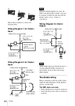
Wiring Diagram 1 for Sensor
Input
Wiring Diagram 2 for Sensor
Input
When the wiring diagram 2 is used, the
NSR is not electrically isolated, so be sure
to construct external circuits that will not
produce noise, excess voltage, or
overcurrents.
Wiring Diagram for Alarm
Output
Alarm output may be activated for up to 2
seconds when the NSR is turned on or
restarted. Be aware of this when using
alarm outputs.
Troubleshooting
Before contacting your Sony dealer, please
check the following items. If the problem
persists, contact them.
The NSR does not work.
• Verify that the power switch is turned on.
• Verify that the power cable is connected
correctly.
2
3
1
Inside of this unit
Outside
3, 5, 7, 9, 11, 13,
15, 17 pin
(SENSOR IN+)
2.35 k
Ω
Sensor device
output:
DC 3.3 V to 24V
2, 4, 6, 8, 10, 12,
14, 16 pin
(SENSOR IN–)
Inside of this unit
Outside
1 pin (VDD)
(200 mA max)
2.35 k
Ω
Wire
Mechanical
switch
or
Open collector
output device
18 pin
(GND)
GND
3, 5, 7, 9, 11, 13,
15, 17 pin
(SENSOR IN+)
2, 4, 6, 8, 10, 12,
14, 16 pin
(SENSOR IN–)
Note
Note
Inside of this unit Outside
5 V
Circuit
example
GND
Magnet relay
24 V AC/24 V
DC, 1 A or less
3, 5, 7, 9, 11, 13,
15, 17 pin
(ALARM OUT+)
2, 4, 6, 8, 10, 12,
14, 16 pin
(ALARM OUT–)