background image

NSP 100

Op
er

at

io

n

System Administrator Setup

20

Settings selected in the “System Administrator 
Setup” screen

The settings selected in the “System Administrator 
Setup” screen are as follows. For details, see the 
respective pages.

Carrying Out “Network Setup”

To make the settings relating to the network, use the 
following procedure.

1

In the “System Administrator Setup” screen, carry 
out any of the following.
• Press numeric button 2, then press the ENTER 

button.

• Using  the 

v

 and 

V

 buttons, select “2. Network 

Setup,” and press the ENTER button.

The “Network Setup” screen appears.

To return to the “System Administrator Setup” 
screen
Carry out any of the following.
• Press numeric button 1, then press the ENTER 

button.

• Using  the 

v

 and 

V

 buttons, select “1. Back to 

System Administrator Setup,” and press the 
ENTER button.

2

Carry out steps 

4

 to 

8

 of the procedure in “Starting 

Up and Initial Settings” (page 10).

3

Carry out any of the following.
• To exit the menu display, press the MENU button.
• To return to the “System Administrator Setup” 

screen, press numeric button 1, or using the 

v

 and 

V

 buttons, select “1. Back to System 

Administrator Setup,” and press the ENTER 
button.

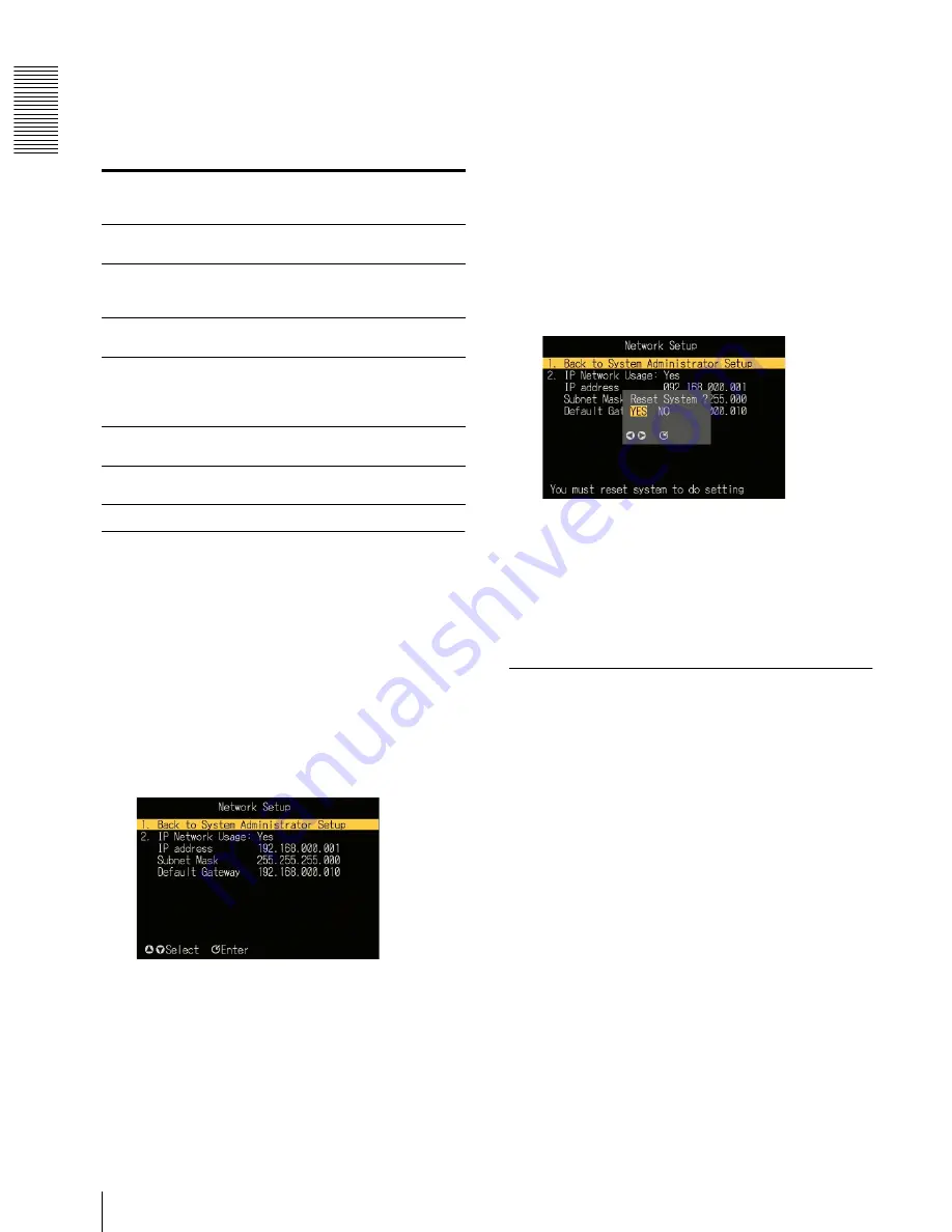
To enable the new network settings, a message 
prompt appears, asking if you want to reset the unit. 

4

To reset immediately, select “Yes”; to reset later, 
select “No.”

The initial screen or “System Administrator Setup” 
screen appears after a reset (for “Yes”) or 
immediately (for “No”).

Carrying Out “RS-232C Setup”

In the “RS-232C Setup” screen, you can select the 
following settings relating to control.
• Protocol control

Select this when using the dedicated control protocol.

• Maintenance

Select this when the RS-232C/GPI connector is to be 
used for maintenance.

• External device control

Select this when the RS-232C/GPI connector is to be 
used for control of an external device.

• Plasma  control

Select this when using a plasma display.

Use the following procedure.

1

In the “System Administrator Setup” screen, carry 
out any of the following.
• Press numeric button 3, then press the ENTER 

button.

• Using the 

v

 and 

V

 buttons, select “3. RS-232C 

Setup,” and press the ENTER button.

Settings that 
can be 
selected

Function of setting

See page

“2. Network 
Setup”

This makes settings related to 
the network.

20

“3. RS-232C 
Setup”

This makes settings related to 
the RS-232C/GPI connector 
and plasma display.

20

“4. Menu 
Language”

Select Japanese or English as 
the menu language.

21

“5. Automatic 
Delete” 

Select whether or not to 
enable the deletion of files for 
which an automatic deletion 
date is set.

22

“6. All Data 
Delete” 

This deletes all data from the 
unit.

22

“7. Password 
Setup” 

This sets a password.

22

Summary of Contents for NSP-100

Page 1: ...NSP 100 Update April 24 2002 Sony Corporation 3 620 271 11 1 Network Player Operating Instructions Before operating the unit please read this manual thoroughly and retain it for future reference ...

Page 2: ...nst harmful interference when the equipment is operated in a commercial environment This equipment generates uses and can radiate radio frequency energy and if not installed and used in accordance with the instruction manual may cause harmful interference to radio communications Operation of this equipment in a residential area is likely to cause harmful interference in which case the user will be...

Page 3: ... Still Image File 13 Deleting Unwanted Playlists and Files 14 Deleting an Unwanted Playlist 14 Deleting Unwanted Movie and Still Image Files 15 Setting the Operating Configuration Setup 16 Displaying the Setup Screen 16 Setting the System Date and Time 16 Making the Delete Confirmation Setting 17 Making the Stop Events Display Setting 17 Making the Playout Log Store Setting 17 Carrying out Playlis...

Page 4: ...ts are available This allows a flexible choice of display monitor Analog audio output Two output channels left and right are available i Link ani Linkconnection toa computer is possible By installing the BZNP 100LE Network Player Management Software included on the supplied CD ROM or the optional BZNP 100 Network Player Management Software2 in the computer content and playlists can be uploaded fro...

Page 5: ...ESS indicator This indicator flashes while data is being read or written to the internal hard disk drive 4 ALARM indicator This flashes or lights when a system error has occurred Flashing A recoverable error occurred Lit An unrecoverable error occurred 5 Remote control optical receiver When operating this unit with the supplied remote controller point the remote controller at this receiver 6 DC IN...

Page 6: ...232C GPI general purpose interface connector D sub 9 pin male Connect to the D sub 9 pin connector of a plasma display or video monitor 7 S400 6 pin IEEE 1394 compliant Connect to the i Link connector of a computer 8 DIP switches The settings of the four switches relate to the video format component video output signal and remote controller The diagramof DIP switch settings above the switches show...

Page 7: ...en in the following sequence Playlist screen list of playlists r Video screen list of movie files r Graphic screen list of still image files During playlist playback Pressing this button displays details of the playlist Press once more to clear the display 3 MENU button When the menu is not displayed Pressing this button switches to menu mode and the MENU screen appears When the menu is displayed ...

Page 8: ...assword is set use these to enter the password 8 Reverse shuttle playback button Press this during movie playback to switch to high speed play shuttle in the reverse direction Press this during shuttle playback in the reverse direction to increase the playback speed During shuttle playback the audio is muted 9 PAUSE button Press this button during playback to pause playback Press once more to resu...

Page 9: ...e the NSP 100 with the remote controller in the DIP switches on the rear panel of the main unit set the third switch from the left to the 1 position ON Then set the remote controller to correspond with the code number setting of the rightmost switch as follows When the code number is 1 the switch is in the 1 position Hold down the STOP and PAUSE buttons on the remote controller then press numeric ...

Page 10: ...er or not to use a network then press the ENTER button If you select No the screen changes as follows In this case skip to step 9 To return to the previous screen To return to the previous screen instead of advancing to step 9 press the b button If you select Yes next press the ENTER button The Network Setup screen reappears 4 Usingthevand Vbuttons select theitemyouwant to set then press the ENTER...

Page 11: ...laying the initial screen Use the BZNP 100 Software For details refer to the Help information for the BZNP 100 Software Displaying the MENU Screen In the initial screen press the MENU button The MENU screen appears In the MENU screen you can select the next screen to be displayed The screens to be displayed are shown in the following table To exit the MENU screen Press the MENU button Screen to be...

Page 12: ...ime the playlist display was shown 2 This is a display for example only If this display were actually present playback would have started when the unit was powered on 2 Using the v and V buttons select the playlist you want to play 3 Press the ENTER button or PLAY button This starts playback of the desired playlist When playback ends the Playlist screen reappears To stop during playback Press the ...

Page 13: ...eo file list screen reappears To stop during playback Press the STOP button Playback stops and the Video file list screen appears Displaying a Still Image File In the Graphic file list screen you can select a desired still image file and display it Use the following procedure 1 In the MENU screen carry out any of the following Press numeric button 3 Using the v and V buttons select 3 Graphic and p...

Page 14: ...t A password entry window appears In this case enter the password with the numeric buttons and press the ENTER button The Delete Files screen appears 2 Carry out any of the following Press numeric button 1 then press the ENTER button Using the v and V buttons select 1 Playlist and press the ENTER button The Delete Playlist screen appears 3 Using the v and V buttons select the playlist to be delete...

Page 15: ... Depending on the selection the Delete Video screen or Delete Graphic screen appears To change the page When the Delete Video screen or Delete Graphic screen is divided into a number of pages to change the page press the b or B button 3 Using the b and B buttons select the movie or still image file to be deleted 4 Press the ENTER button A message appears prompting you to confirm the deletion In th...

Page 16: ...meric button 1 then press the ENTER button Using the v and V buttons select 1 System Time and press the ENTER button The screen now allows the date and time to be set 2 Using the b and B buttons select the item to set date or time Settings that can be selected Function of setting See page 1 System Time Set the system date and time 16 2 Delete Confirmation Select whether or not to display a confirm...

Page 17: ...s the ENTER button This confirms the setting Making the Stop Events Display Setting During a break in a playlist while waiting for the next event playback select whether to display the last still image or a black background Use the following procedure 1 In the Setup screen carry out any of the following Press numeric button 3 then press the ENTER button Usingthe vandVbuttons select 3 StopEvents Di...

Page 18: ... the ENTER button Using the v and V buttons selec 5 Playlist Mode Setup and press the ENTER button The Playlist Mode Setup screen appears 2 Using the v and V buttons select the playlist for which you want to make the setting and press the ENTER button The Playlist Mode Setup window appears 3 Using the v and V buttons select Power On or One Touch Power On Automatic playback at power on One Touch PL...

Page 19: ...st the other item repeat steps 2 to 4 6 When the adjustments are complete press the v button to select Set then press the ENTER button The adjustments are reflected in the screen display System Administrator Setup To carry out system administrator setup display the System Administrator Setup screen Displaying the System Administrator Setup Screen To display the System Administrator Setup screen in...

Page 20: ... asking if you want to reset the unit 4 To reset immediately select Yes to reset later select No The initial screen or SystemAdministrator Setup screen appears after a reset for Yes or immediately for No Carrying Out RS 232C Setup In the RS 232C Setup screen you can select the following settings relating to control Protocol control Select this when using the dedicated control protocol Maintenance ...

Page 21: ...nd press the ENTER button This confirms the setting To exit the RS 232C Setup screen Carry out any of the following operations Press the MENU button Press numeric button 1 or using the v and V buttons select 1 Back to System Administrator Setup and press the ENTER button To enable the new RS 232C settings a message prompt appears asking if you want to reset the unit To reset immediately select Yes...

Page 22: ...re 1 In the System Administrator Setup screen carry out any of the following Press numeric button 6 then press the ENTER button Using the v and V buttons select 6 All Data Delete and press the ENTER button A message appears prompting you to confirm the deletion of all data Note If in the Setup screen the setting for 2 Delete Confirmation is No then this confirmation message does not appear 2 Using...

Page 23: ...ystem Administrator Setup 23 3 Enterthe passwordcreatedinstep2 oncemore and press the ENTER button This sets the password To cancel the password In steps 2 and 3 press the ENTER button without entering any number ...

Page 24: ...ons Connecting the Power Using the supplied AC adapter and AC cable make the connections shown in the following figure To DC IN 12V connector DC IN 12V DC cable AC adapter To AC input connector AC cable To 100 V AC supply To DC IN 12 V connector ...

Page 25: ...O OUT RS 232C GPI COMPOSITE 1 S400 VIDEO IRD REMOTE NTSC PAL 1 2 S OUT G Y B B Y R R Y 2 1 2 COMPONENT RGB ON OFF 1 2 Video input connector Plasma display video monitor Audio monitor system Video output connectors Y R Y B Y RGB S VIDEO COMPOSITE Network Ethernet RS 232C GPI Note To operate this system requires the BZNP 100 Software RS 232C AUDIO OUT 1 2 ...

Page 26: ...OSITE 1 S400 VIDEO IRD REMOTE NTSC PAL 1 2 S OUT G Y B B Y R R Y 2 1 2 COMPONENT RGB ON OFF 1 2 Video input connector Plasma display video monitor Audio monitor system Video output connectors Y R Y B Y RGB S VIDEO COMPOSITE Computer S400 RS 232C GPI Note The BZNP 100 Software must be installed in the computer RS 232C AUDIO OUT 1 2 IEEE 1394 ...

Page 27: ...uting content and playlists through Ethernet to multiple NSP 100 units Computer Video monitor Audio monitor Ethernet NSP 100 Video monitor Audio monitor NSP 100 Video monitor Audio monitor NSP 100 Note The BZNP 100 Software must be installed in the computer ...

Page 28: ...ing the unit or otherwise imparting a violent shock to it is likely to cause it to malfunction Avoid violent impacts Dropping the unit or otherwise imparting a violent shock to it is likely to cause it to malfunction Do not obstruct ventilation openings To prevent the unit from overheating do not obstruct ventilation openings by for example wrapping the unit in a cloth while it is in operation On ...

Page 29: ...Sony Corporation http www sony net ...

Reviews: