


13
MZ-R910
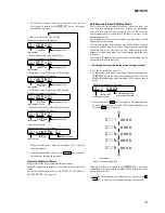
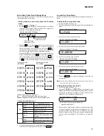
Operation in Setting the Test Mode
• When the test mode becomes active, first the display check mode
is selected.
• Other mode can be selected from the display check mode.
• When the test mode is set, the LCD repeats the following dis-
play.
Remote commander LCD display
•
When the
X
key is pressed and hold down, the display at that
time is held so that display can be checked.
Releasing the Test Mode
For test mode set with the method
1
:
Turn off the power and open the solder bridge on SL801 (TEST)
on the MAIN board.
Note:
Remove the solders completely. Remaining could be shorted with
the chassis, etc.
For test mode set with the method
2
or
3
:
Turn off the power.
888
001
V1.000
Microcomputer
version
display
All off
All lit
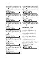
2
In the normal mode, turn on the
[HOLD]
switch. While press-
ing the
[VOLUME --]
key press the following order:
>
t
>
t
.
t
.
t
>
t
.
t
>
t
.
t
X
t
X
3
In the normal mode, turn on the
[HOLD]
switch. While
pressing the
x
/
CHG
key, press the keys on the remote
commander with the following order:
N >
t
N >
t
.
t
.
t
N >
t
.
t
N >
t
.
t
X
t
X
Note:
If electrical adjustment (CD and MO overall adjustment) has not
been finished completely, “NV Error” is displayed on LCDs of the
set and the remote commander.
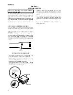
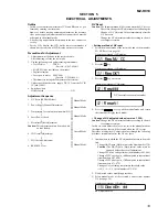
SECTION 4
TEST MODE
Outline
• This set provides the Overall adjustment mode that allows CD
and MO discs to be automatically adjusted when in the test mode.
In this overall adjustment mode, the disc is discriminate between
CD and MO, and each adjustment is automatically executed in
order. If a fault is found, the system displays its location. Also,
the manual mode allows each individual adjustment to be auto-
matically adjusted.
• Operation in the test mode is performed with the set. A key
having no particular description in the text, indicates a set key.
• For the LCD display, the LCD on the remote commander is
shown, but the contents of LCD display on the set are same.
Setting Method of Test Mode
There are three different methods to set the test mode:
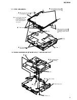
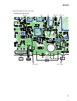
1
Short SL801 (TEST) on the MAIN board with a solder bridge
(connect pin
<zvn
of IC801 to the ground) and turn on the
[HOLD]
switch. Then, turn on the power.
CN502
1
0
1
44
IC501
C509
C519
C513
C511
C510
C808
C508
C850
R855
C811
C813
C818
C821
C810
C820
SL801(TEST)
SL801
TEST
– MAIN Board (Conductor Side) –
Summary of Contents for MZ-R910
Page 75: ...75 MZ R910 MEMO ...


