background image

MHC-V5

33

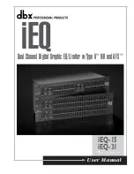
2-29.  VOLUME  KNOB  BLOCK

2

 volume knob block

hole

1

 Push the volume knob block 


by flat-head screwdriver.

top panel block

volume knob block

rib

shaft

Note 1:

 When installing the volume knob block, 


aline the two ribs of volume knob and

 the 

shaft.

‡+RZWRLQVWDOOWKHYROXPHNQREEORFN

±

B

RWWRPYLHZ

7RSYLHZ

Note 2:

 When installing the volume knob block, 


please apply suncall (CFD-703Z) to rib 


and shaft inside.

‡$SSOLFDWLRQSRVLWLRQRIVXQFDOO&)'=

rib

shaft

B

RWWRPYLHZ

Summary of Contents for MHC-V5

Page 1: ...objective lens surface on the Optical Pick up Block with 7 mm aperture Frequency response 20 Hz 20 kHz Signal to noise ratio More than 90 dB Dynamic range More than 88 dB Tuner section FM stereo FM AM superheterodyne tuner Antenna FM lead antenna AM loop antenna FM tuner section Tuning range USA model 87 5 MHz 108 0 MHz 100 kHz step Other models 87 5 MHz 108 0 MHz 50 kHz step AM tuner section Tuni...

Page 2: ...T WARNING COMPONENTS IDENTIFIED BY MARK 0 OR DOTTED LINE WITH MARK 0 ON THE SCHEMATIC DIAGRAMS AND IN THE PARTS LIST ARE CRITICAL TO SAFE OPERATION REPLACE THESE COMPONENTS WITH SONY PARTS WHOSE PART NUMBERS APPEAR AS SHOWN IN THIS MANUAL OR IN SUPPLEMENTS PUBLISHED BY SONY License and Trademark Notice WALKMAN and W ALKMAN logo are registered trademarks of Sony Corporation MPEG Layer 3 audio codin...

Page 3: ... Schematic Diagram MAIN Section 2 9 44 5 7 Schematic Diagram MAIN Section 3 9 45 5 8 Schematic Diagram MAIN Section 4 9 46 5 9 Schematic Diagram MAIN Section 5 9 47 5 10 Schematic Diagram MAIN Section 6 9 48 5 11 Schematic Diagram MAIN Section 7 9 49 5 12 Schematic Diagram MAIN Section 8 9 50 5 13 Schematic Diagram MAIN Section 9 9 51 5 14 Printed Wiring Boards MAIN Section 1 2 52 5 15 Printed Wir...

Page 4: ... surface by the objective lens in the optical pickup block Therefore when checking the laser diode emission observe from more than 30 cm away from the objective lens NOTE OF REPLACING THE MS 476 BOARD When the MS 476 board is defective exchange the CDM90 ASSY Ref No CDM1 NOTE OF REPLACING THE IC001 IC002 IC105 IC106 IC302 AND IC306 ON THE ARAGON BOARD IC001 IC002 IC105 IC106 IC302 and IC306 on the...

Page 5: ...istor to both ends of respective capacitors D AMP board CN1000 pin 6 and 10 pin 6 and 3 Switching regurator SWR1 C202 C203 C403 C407 C531 and C532 Switching Regurator Conductor Side D AMP Board Conductor Side 800 2 W for C403 800 2 W for C407 800 2 W for C531 800 2 W for C532 800 2 W for C203 800 2 W for C202 800 2 W pin 3 and 6 800 2 W pin 6 and 10 1 10 CN1000 ...

Page 6: ...are removed this work is done Note 2 Please prepare the thin wire clip etc processed to the length of 8 cm or more tray CD mechanism deck Top view hole 8 cm or more 2 Draw out the tray 1 Insert the clip etc in the hole and push the lever in the direction of the arrow thin wire clip etc Left view hole ...

Page 7: ...10 ARAGON BOARD 2 Page 16 2 12 D AMP BOARD 1 Page 17 2 13 D AMP BOARD 2 Page 18 2 14 SUB CHASSIS Page 19 2 15 FRONT PANEL 1 Page 19 2 16 FRONT PANEL 2 Page 20 2 17 SWITCHING REGULATOR SWR1 Page 21 2 30 HOW TO BEND WIRE FLAT TYPE Page 34 2 24 BLUETOOTH MODULE BT1 Page 28 2 25 USB BOARD BLOCK Page 29 2 26 NFC MODULE NFC1 Page 30 2 18 FRONT PANEL SP BLOCK Page 22 2 19 SPEAKER LED BOARD FRONT PANEL SP...

Page 8: ...behind the second fin and press in the direction of the arrow Note Do not damage screw cap 5 Remove the side R panel block in the direction of the arrow 5 Remove the side L panel block in the direction of the arrow 4 three screws BVTP3 u 10 4 three screws BVTP3 u 10 6 side L panel block 3 screw cap 3 screw cap needle nose pliers 1 Insert needle nose pliers behind the second fin and press in the di...

Page 9: ...re VeWWiQJ guide line guide line guide line guide line 7RS reDr YieZ Note 1 Fix the cushion H so that the wire flat type does not come in contact with the heat sink wire flat type 15 core Note 2 When installing the wire flat type ensure that the colored line is not slanted after insertion colored line colored line Insert is straight to the interior Insert is incline wire flat type wire flat type c...

Page 10: ...L BLOCK 1 Insert the clip etc in the hole and push the lever in the direction of the arrow 2 Draw out the tray tray CD mechanism deck thin wire clip etc Top view Left view hole 3 two claws 4 loading panel block 8 cm or more hole ...

Page 11: ...k cap in the direction of the arrow 4 chuck cap 2 claw 2 claw 2 claw Note 3 When installing the chuck cap align the triangle marks OK NG 5 Solder the short land Note 2 When assembling the CDM block remove the solder of short land after connecting flexible flat cable 24P CN302 Solder is removed cleanly Solder is not removed OK NG 1 cushion E cushion E guide line ...

Page 12: ... line is not slanted after insertion colored line colored line Insert is straight to the interior Insert is incline flexible flat cable flexible flat cable connector connector OK NG Note 1 Connect the wire from the CDM block to the ARAGON board and place it neatly inside the CDM block Note 3 When you install the connector please install them correctly There is a possibility that this machine damag...

Page 13: ...MHC V5 13 2 7 DUCT 3 Remove the duct in the direction of the arrow 4 duct 1 two screws BV RING 1 two screws BV RING 1 two screws BV RING 2 hook ...

Page 14: ...slanted after insertion colored line colored line Insert is straight to the interior Insert is incline flexible flat cable flexible flat cable connector connector OK NG Note 3 When you install the connector please install them correctly There is a possibility that this machine damages when not correctly installing it Insert is shallow Insert is straight to the interior connector Insert is incline ...

Page 15: ...alling the wire flat type ensure that the colored line is not slanted after insertion colored line colored line Insert is straight to the interior Insert is incline wire flat type wire flat type connector connector OK NG Note 2 When you install the connector please install them correctly There is a possibility that this machine damages when not correctly installing it Insert is shallow Insert is s...

Page 16: ...board FL board cushion H 3 wire flat type 23 core CN109 2 wire flat type 8 core CN105 1 cushion H 7RS UHDU YLHZ Note When installing the wire flat type ensure that the colored line is not slanted after insertion colored line colored line Insert is straight to the interior Insert is incline wire flat type wire flat type connector connector OK NG 2 10 ARAGON BOARD 2 Continued on 2 11 ...

Page 17: ...connector please install them correctly There is a possibility that this machine damages when not correctly installing it Insert is shallow Insert is straight to the interior connector Insert is incline connector connector connector connector connector OK NG NG eIW view yellow red blue filament tape sub material filament tape sub material 2 12 D AMP BOARD 1 Continued on 2 13 page 18 ...

Page 18: ... 4 two screws PTPWH2 6 u L to D AMP board short long 3 coating clip 8 D AMP board 5 bracket HS Note When installing the wire flat type ensure that the colored line is not slanted after insertion colored line colored line Insert is straight to the interior Insert is incline wire flat type wire flat type connector connector OK NG 7RS UHDU YLHZ Terminal face is below side D AMP board CN1006 ...

Page 19: ... Top rear view 3 Draw out the wire from hole hole LUH VHWWLQJ LUH VHWWLQJ LUH VHWWLQJ LUH VHWWLQJ FL board coating clip coating clip coating clip coating clip 7RS UHDU YLHZ 4 Remove the wire from the coating clip 2 Remove the wire from the coating clip 3 Remove the wire from the coating clip 1 Remove the wire from the coating clip FL board USB board FL board ...

Page 20: ...de side black 2 terminal wide side black 3 connector CN2002 Note 2 When you install the connector please install them correctly There is a possibility that this machine damages when not correctly installing it Insert is shallow Insert is straight to the interior connector Insert is incline connector connector connector connector connector OK NG NG C C 4 two screws BVTP3 u 8 4 two screws BVTP3 u 8 ...

Page 21: ...tor CN401 2 connector CN101 Note When you install the connector please install them correctly There is a possibility that this machine damages when not correctly installing it Insert is shallow Insert is straight to the interior connector Insert is incline connector connector connector connector connector OK NG NG 1 Remove the wire from the coating clip ire VeWWiQJ switching regulator SWR1 coating...

Page 22: ...ert the jig into the space and slowly remove the front panel SP block Note 1 When using a jig please work so as not to injure front panel SP block and speaker cabinet 3 Insert the jig into the space and slowly remove the front panel SP block Note 1 When using a jig please work so as not to injure front panel SP block and speaker cabinet 4 All bosses are removed while moving jig in the direction of...

Page 23: ...0 5 sleeve ferrite clamp FC5 2 screw BVTP3 u 8 5 front panel SP assy Wrap twice SPEAKER LED board total six grooves cushion H cushion H Note When you install the connector please install them correctly There is a possibility that this machine damages when not correctly installing it Insert is shallow Insert is straight to the interior connector Insert is incline connector connector connector conne...

Page 24: ...rminal position loudspeaker 25 cm SP5 2 Remove the loudspeaker 25 cm SP5 in the direction of the arrow 1 six screws BVTP4 u 20 3 terminal narrow side black 3 terminal wide side red 4 loudspeaker 25 cm woofer SP5 RZ WR LQVWDOO WKH ORXGVSHDNHU FP 63 ...

Page 25: ...SP1 in the direction of the arrow 1 Remove the speaker cable 2 four tapping screws 3 5 u 14 4 terminal narrow side 4 terminal wide side 5 loudspeaker 10 cm mid L ch SP1 terminal wide side groove terminal narrow side LUH VHWWLQJ LUH VHWWLQJ loudspeaker 10 cm SP1 rib speaker cable rib RZ WR LQVWDOO WKH ORXGVSHDNHU FP 63 ...

Page 26: ... 3 four tapping screws 3 5 u 14 6 loudspeaker 10 cm mid R ch SP3 5 terminal narrow side 5 terminal wide side 1 cushion H cushion H terminal position loudspeaker 10 cm SP3 terminal wide side groove terminal narrow side LUH VHWWLQJ LUH VHWWLQJ LUH VHWWLQJ loudspeaker 10 cm SP3 rib wire rib RZ WR LQVWDOO WKH ORXGVSHDNHU FP 63 wire ...

Page 27: ... line guide line 1 cushion H cushion H erriWe FRre VeWWiQJ flexible flat cable ferrite core FC4 cushion E 0 5 erriWe FRre VeWWiQJ wire flat type 23 core ferrite core FC1 cushion E 0 5 short long Note When installing the wire flat type ensure that the colored line is not slanted after insertion colored line colored line Insert is straight to the interior Insert is incline wire flat type wire flat t...

Page 28: ...QJ Note When installing the wire flat type ensure that the colored line is not slanted after insertion colored line colored line Insert is straight to the interior Insert is incline wire flat type wire flat type connector connector OK NG RZ WR iQVWDOO WKe EOXeWRRWK PRGXOe 7 to bluetooth module BT1 OK NG Terminal face is below side Terminal face bluetooth module BT1 bluetooth module BT1 2 Remove th...

Page 29: ...crews BVTP3 u 8 erriWe FRre VeWWiQJ cushion E 0 5 ferrite core FC3 guide line Wrap once 3 Remove the USB board block in the direction of the arrow Note When installing the wire flat type ensure that the colored line is not slanted after insertion colored line colored line Insert is straight to the interior Insert is incline wire flat type wire flat type connector connector OK NG to USB board Termi...

Page 30: ... 3 Peel off the adhesive sheet NFC 7 Peel off the tape NFC long Note When installing the wire flat type ensure that the colored line is not slanted after insertion colored line colored line Insert is straight to the interior Insert is incline wire flat type wire flat type connector connector OK NG Wire VHWWLQJ 4 Remove the NFC module block in the direction of the arrow Wire VHWWLQJ OK NG Terminal ...

Page 31: ...5 Draw out the flexible flat cable 24 core from hole 4 Remove the FFC holder in the direction of the arrow CD mechanism deck block bottom view 6 FFC holder Note When installing the FFC holder check that installed firmly two bosses and claw hole ow to install the C holdeU 3astinJ Sosition oI cXshion There is a gap There is no gap OK NG Bottom view ...

Page 32: ... flexible flat cable ensure that the colored line is not slanted after insertion colored line colored line Insert is straight to the interior Insert is incline flexible flat cable flexible flat cable connector connector OK NG Note 2 When you install the connector please install them correctly There is a possibility that this machine damages when not correctly installing it Insert is shallow Insert...

Page 33: ...volume knob block rib shaft Note 1 When installing the volume knob block aline the two ribs of volume knob and the shaft RZ WR LQVWDOO WKH YROXPH NQRE EORFN BRWWRP YLHZ 7RS YLHZ Note 2 When installing the volume knob block please apply suncall CFD 703Z to rib and shaft inside SSOLFDWLRQ SRVLWLRQ RI VXQFDOO rib shaft BRWWRP YLHZ ...

Page 34: ... 5HI 1R The upper side is terminal side ARAGON board CN302 ARAGON board CN110 D AMP board CN1006 ARAGON board CN851 optical pick up The lower side is terminal side Mountain fold Valley fold tuner unit 105 mm 20 mm The lower side is terminal side The lower side is terminal side 40 mm The lower side is terminal side The lower side is terminal side 55 1 5 mm ...

Page 35: ...eously 5 The message 9K STEP or 10K STEP is displayed on the fluorescent indicator tube and AM step interval changed Screen display or DISC TRAY LOCK MODE It can be unable to take sample disc out of disc tray in the shop Procedure 1 Press the 1 button to turn the power on 2 Press the FUNCTION button to turn the CD function 3 Press the Z button to open the disc tray and set the CD 4 Press the Z but...

Page 36: ... pattern 1 Speaker illumination red Test pattern 2 Speaker illumination green 1 REC cPLAY SHUF 1 USB USB USB B VIDEO PHOTO MUSIC MONO AUTO 1 NX REC cPLAYcREC FLDR SHUF 1 USB PGM ALL USB SEARCH USB B VIDEO PHOTO MUSIC TUNED MONO AUTO USB A NTSC SLEEP PRESET STEREO cREC FLDR PGM ALL SEARCH TUNED USB A NTSC SLEEP PRESET STEREO 1 NX REC cPLAYcREC FLDR SHUF 1 USB PGM ALL USB SEARCH USB B VIDEO PHOTO MU...

Page 37: ... B and C signals When the selected station signal is received in good condition TUNED is displayed CD SECTION Note 1 CD block is basically constructed to operate without adjustment 2 Use HLX A1 disc Part No J 2501 307 A unless otherwise indicat ed 3 Clean the object lens by an applicator with lens cleaning liquid when the servo check result is NG SERVO CHECK Procedure 1 Press the 1 button to turn ...

Page 38: ...K 16 VOTK 15 VOTK TRK TRK 22 FOO 1 VINFC 45 MUTE 28 MUTE 2 SO 5 SI SERIAL FLASH IC302 31 SF_DO 24 USB_DM 25 USB_DP 106 ADIN 118 ASDATA0 113 ABCK 117 ALRCK 112 ACLK 32 SF_DI 6 SCK 33 SF_CK 1 _CS 30 SF_CS RD0 RD15 17 CAS DG0 DQ1 DQ15 RA0 RA11 A0 A9 A10 AP A11 18 RAS SD RAM IC306 82 CAS 83 RAS 15 LDQM 61 DQM0 39 UDQM 70 DQM1 20 BA0 21 BA1 85 BA0 86 BA1 38 CLK 72 RCLK 16 WE 80 RWE 14 VOFC 13 VOFC FCS ...

Page 39: ...LECTOR IC602 3 Y 10 9 A B INVERTER Q604 INVERTER Q611 R CH MUTING Q602 BT RXD BT TXD BT1 Bluetooth MODULE BT RESET 1 A 2 B DIGITAL AUDIO SELECTOR IC608 5 Y 6 SEL 2 7 DATA VOUTL 8 VOUTR 1 BCK 3 LRCK 16 SCK D A CONVERTER IC604 R CH LINE AMP IC603 R CH L J601 1 2 AUDIO IN PARTY CHAIN IN R J601 2 2 L R LINE AMP IC601 AUDIO OUT PARTY CHAIN OUT R CH MUTING CONTROL Q606 LINK SET CONTROL Q603 ST CLK ST CE...

Page 40: ...TING CONTROL Q109 136 AMP CLK FR 132 DC DET 3 14 IN HO 11 LO 13 VS 5 CSD AUDIO AMP IC1011 BOOSTER Q1028 BOOSTER Q1030 3 14 IN HO 11 LO 13 VS 5 CSD AUDIO AMP IC1009 BOOSTER Q1023 BOOSTER Q1025 3 14 IN HO 11 LO 13 VS 5 CSD AUDIO AMP IC1012 BOOSTER Q1032 BOOSTER Q1034 CLOCK BAND PASS FILTER IC1003 POWER ON OFF SWITCH Q1031 SHUTDOWN SWITCH Q1058 POWER ON OFF SWITCH Q1026 POWER ON OFF SWITCH Q1036 RESE...

Page 41: ...K 21 PWMCLK 4 TRANS 8 OUT3 6 OUT1 D2100 DJ EFFECT FLANGER 13 OUT8 D2101 DJ EFFECT ISOLATOR 7 OUT2 D2102 DJ EFFECT WAH 14 OUT9 D2103 DJ EFFECT PAN 10 OUT5 D2108 BASS BAZUCA 11 OUT6 D2109 CONNECTION PAIRING Bluetooth 16 OUT11 17 OUT12 18 OUT13 D1800 GRN RED BLU D2104 2110 ILLUMINATION 15 OUT10 D2105 2111 ILLUMINATION 9 OUT4 D2150 2153 ILLUMINATION 12 OUT7 D2151 2152 ILLUMINATION THERMISTOR PROTECT 7...

Page 42: ...s extracted from the component side Y Parts extracted from the conductor side Pattern from the side which enables seeing The other layers patterns are not indicated Circuit Boards Location Indication of transistor C B These are omitted E Q Caution Pattern face side Conductor Side Parts face side Component Side Parts on the pattern face side seen from the pattern face are indicated Parts on the par...

Page 43: ... JL338 JL335 JL311 JL330 JL305 JL312 JL309 JL306 JL314 JL301 JL315 JL321 JL308 JL323 JL324 JL319 JL317 JL307 JL333 JL329 JL334 JL304 JL328 JL302 JL316 JL325 JL337 JL327 JL318 JL332 JL320 JL322 JL331 JL313 JL310 JL303 JL353 JL352 JL351 JL350 JL349 JL348 JL347 JL346 JL345 JL344 JL354 JL343 JL342 JL341 JL340 RB309 22 RB301 22 22 RB304 22 RB302 22 RB305 22 RB303 22 RB306 22 RB308 22 RB307 XIFBSY FE_LI...

Page 44: ...RK FE_LD_CD FE_LD_DVD LOAD LOAD FE_OPO FE_3 3V FE_OP FE_FCS SL402 SL404 SL403 SL407 SL406 SL405 SL408 SL401 15 R423 15 R425 15 R427 15 R428 15 R426 47k R431 15 R430 100 R432 100k R429 0 R433 100 R421 47k R422 100k R424 0 01 C421 0 01 C424 35V 47 C420 2SA2119K Q402 2SA2119K Q401 0 1 C418 0 1 C419 C406 0 1 C405 0 1 R409 10k R410 10k RB520S 30FJTE61 D401 RB520S 30FJTE61 D402 R404 1 1 2W 10V 100 C412 ...

Page 45: ...20p C686 3 3k R766 10k R770 47p C708 100p C689 100p C692 0 R763 0 R747 10 C697 10 C688 R910 10 R797 10 R796 10 R795 0 1 C751 0 1 C754 0 1 C753 0 1 C752 6 3V 470 C726 0 R794 0 R792 0 1 C741 C695 0 1 10 C691 0 R859 0 R857 0 R855 0 R854 0 R852 R851 0 0 R856 C744 0 1 C743 10 C740 100p R798 0 C742 10 C748 10 R819 10 4 7k R908 4 7k R907 6 3V 47 C913 0 1 C914 10 C724 2 7k R806 10k R800 3 3k R799 2 7k R80...

Page 46: ...16 4 7k R607 470k R615 470k 68k R644 4 7 C766 C601 4 7 C607 0 1 C605 47 4 7 C767 4 7 C602 4 7 C631 47k R657 1M R658 47k R659 R639 47k 47k R906 47k R683 47k R684 47k R682 1M R665 47k R666 1M R681 47k R664 4 7 C637 4 7 C638 4 7 C658 4 7 C661 47k R695 1M R693 47k R696 47k R694 C651 0 1 0 1 C656 R635 47k R646 47k R633 47k R648 1M R636 1M R647 47k R634 47k R645 47k 4 7 C625 C616 0 1 4 7 C610 R610 47k R...

Page 47: ...D1_0 ASDATA0 SRC RST0 ARAGON BCK3 ARAGON LRCK3 ADIN DIN3 2 7k R618 4 7k R626 1 5k R617 1 5k R638 2 7k R619 4 7k R640 4 7k R622 4 7k R609 0 1 C615 10 C618 47 C614 0 001 C603 820p C608 47p C604 47 C619 3 3k R620 10k R614 0 R643 0 R629 100p C624 47 C632 100p C630 10 C609 10 C622 0 1 C617 10 R631 10 R630 10 R632 R820 10 0 1 C649 10 C655 0 1 C653 C642 10p C644 10p 0 1 C646 10 C645 10 R691 10 R688 0 R67...

Page 48: ...SET 14 TEST SCL 15 DVDD 16 PGANG 17 OVCUR2 SMD 18 PWREN2 19 OVCUR1 SMC 20 PWREN1 SDA 21 AVDD_22 22 DM0 23 DP0 24 D 3 3V USB 5V SW 13V USBP USBM HUB RST GND USB OC 12MHz X451 0 1 C455 10 C453 10k R455 100k R453 10k R452 100 R451 10k R454 0 1 C451 0 1 C452 27p C457 27p C456 0 1 C454 1k R456 1k R457 680 R460 0 1 C459 22k R463 100 R462 R472 0 10k R469 C467 0 1 0 1 C465 0 1 C463 16V 10 C462 C460 0 1 10...

Page 49: ...T BU4229F TR IC103 GND 1 VDD 2 CT 3 VOUT 4 TC74VHC126FT EKJ IC102 1 2 3 4 5 6 GND 7 8 9 10 11 12 13 VCC 14 AC CUT JL269 1k R128 0 1 C107 0 R126 R119 0 R122 0 0 1 C110 0 1 C104 C105 2200p 6 3V 47 C103 10k R117 1k R115 KRC402 RTK Q107 KRC402 RTK Q104 10k R108 2 2k R109 2SB1710TL Q103 47k R116 0 1 C102 0 1 C106 1 C109 10k R127 47 R132 47 R135 47 R134 100 R131 47 R133 100 R130 100 R129 47k R120 47k R1...

Page 50: ...8MHz X103 32 768kHz X101 JL268 JL210 IC106 CS 1 SO SIO1 2 WP SIO2 3 GND 4 SI SIO0 5 SCLK 6 HOLD SIO3 7 VCC 8 4 7k R244 4 7k R246 4 7k R260 4 7k R264 4 7k R268 4 7k R250 4 7k R253 100 R258 100 R262 100 R266 100 R245 100 R248 100 R252 100 R255 100 R243 10k R282 100 R227 100 R166 100 R238 47 R100 100 R236 100 R241 100 R228 47 R214 47 R212 100 R233 47 R222 47 R220 47 R217 100 R223 100 R225 10k R298 0 ...

Page 51: ...710TL Q004 0 1 C085 0 33 C062 16V 100 C057 10V 100 C072 0 1 C068 0 1 C074 0 1 C075 0 1 C064 100 C066 0 R051 0 R052 0 R054 0 R053 0 R048 0 R047 1 C071 0 1 C065 10V 100 C067 10V 100 C073 220 R034 10k R039 680 R030 470 R040 10k R037 10k R028 2SB1690KT146 Q002 2SB1690KT146 Q005 2SB1710TL Q007 KRC402 RTK Q006 0 1 C048 0 1 C045 22 C053 C046 0 022 22 C050 C047 0 022 0 R018 12k R041 22k R043 R022 15 0 1 C...

Page 52: ...19 12 2 1 23 22 1 3 1 23 1 4 5 6 1 1 6 2 24 1 2 19 18 1 6 3 4 1 3 4 6 1 6 3 4 1 6 3 4 1 176 44 45 88 89 133 132 3 4 1 2 1 6 3 4 128 33 32 1 65 96 64 97 5 4 8 1 R018 R402 R404 R021 R215 R022 R023 R218 R219 R608 R609 R221 R030 R224 R226 D572 R034 R611 R229 R612 R613 R616 R617 R230 R618 R619 R232 C003 R040 C004 R234 C005 R235 C006 R236 C007 C008 R620 C009 R239 R624 R627 R629 C012 C013 C014 R820 C017 ...

Page 53: ... 1 4 5 8 16 9 16 9 1 8 1 8 1 7 8 14 1 4 8 5 1 4 8 5 14 1 15 28 1 16 8 9 1 16 8 9 1 4 5 8 1 4 5 8 1 5 1 4 5 8 1 6 3 4 8 14 1 7 1 4 5 8 5 4 8 1 1 6 3 4 1 4 5 8 27 28 1 54 1 6 3 4 R212 R214 R216 R217 R600 R602 R603 R604 R029 R605 R220 R223 R225 R033 R227 R228 R035 R806 R037 R807 R809 R421 R422 R423 R425 R426 R427 R428 R429 R621 R816 R047 R048 R430 R431 R432 R240 R244 R051 R052 R246 R054 R248 C404 R25...

Page 54: ...R1203 R1204 R1010 Q1034 Q1035 R1205 IC1009 R1011 R1206 Q1036 R1207 R1013 Q1037 C1231 C1232 R1017 R1018 IC1011 R1019 IC1012 R1210 C1238 IC1015 R1211 Q1042 IC1016 R1213 R1214 D1024 R1215 R1021 D1025 R1216 R1022 D1026 D1027 R1600 R1024 D1028 D1029 R1603 R1027 R1028 C1244 R1029 C1245 C1246 D1030 C1248 R1221 D1031 C1249 R1222 D1032 R1223 R1224 R1030 D1034 R1225 R1031 D1035 R1032 D1036 R1227 R1033 D1037...

Page 55: ... C1212 CL1074 CL1075 CL1079 CL1080 C1223 CL1084 CL1085 R1208 C1234 C1236 C1237 C1239 R1212 TH1008 TH1009 C1240 R1601 C1241 R1602 C1243 R1604 TH1010 C1247 R1228 R1229 R1617 C1257 C1258 C1259 R1234 R1239 C1267 C1268 C1269 R1243 R1244 C1272 R1250 R1253 R1254 R1645 R1646 R1271 R1275 R1662 C1498 CL1107 R1669 R1286 R1671 R1291 R1293 R1294 R1296 C1112 1 10 1 3 1 3 1 2 1 3 L1011 L1012 L1014 L1015 L1017 L1...

Page 56: ... 7 C1004 4 7 C1000 2SC4081T106R Q1002 LTA014EUBFS8TL Q1003 2SA1576A T106 QR Q1000 10k R1027 150k R1038 10k R1032 2SC3906K T146E Q1004 0 47 C1022 0 1 C1023 16V 47 C1021 25V 47 C1497 22k R1007 180k R1005 22k R1006 120k R1004 120k R1001 180k R1008 47k R1002 47k R1003 DZ2J068M0L D1002 DZ2J068M0L D1008 DZ2J140M0L D1007 3 9k R1662 3 9k R1661 3 3 R1570 3 3 R1573 12k R1660 3 3k R1663 47k R1659 10k R1557 2...

Page 57: ...7 220 R1206 3 3k R1207 3 3k R1208 2 2k R1199 4 7 R1201 4 7 R1222 1k R1215 0 01 C1171 0 0022 C1174 1000p C1172 0 0022 C1175 470p C1166 10 C1185 0 01 C1167 220k R1210 5 6k R1224 330 R1629 4 7k R1225 4 7 R1252 2 2k R1250 R1591 0 100 R1243 0 01 C1210 0 01 C1225 1000p C1226 0 0022 C1231 470p C1209 0 0022 C1228 6 3V 47 C1211 6 3V 47 C1227 6 3V 47 C1173 6 3V 47 C1168 0 22 C1192 22 C1170 82k R1214 0 R1213...

Page 58: ...N2202 CN2203 CN2204 C2200 C2203 S2200 S2201 JW2700 JW2701 JW2702 JW2703 JW2704 W001 JW2705 W002 CL2205 CL2206 CL2207 C2201 R2212 USB BOARD ARAGON BOARD CN451 02P A K K A K A CHASSIS CHASSIS A K K K A A ARAGON BOARD CN451 01P TOP KEY A BOARD CN2102 05P 1 889 851 11 11 S2200 2201 A K K A A K K A REC TO USB B ENTER A K K A A K K A FFC8 A K A K US E2 E51 E2 E51 US E2 E51 US A K A K US US E2 E51 US REC...

Page 59: ...201 DZ2J068M0L D2201 DZ2J068M0L D2203 DZ2J068M0L D2207 0 R2204 0 R2203 0 01 C2212 10 C2211 0 R2215 0 R2214 0 R2213 FB2200 DZ2J068M0L D2200 DZ2J068M0L D2202 DZ2J068M0L D2205 10 C2206 0 01 C2209 0 R2202 0 R2201 0 R2211 0 R2212 0 R2210 6 3V 100 C2200 6 3V 100 C2203 E ET001 E ET002 ENTER S2200 REC TO USB B S2201 USB BOARD 1 2 3 4 1 2 3 4 2 NC 6P 5P 2 NC FFC8 CN2102 TOP KEY A 05S BOARD BOARD 02S CN451 ...

Page 60: ...C2035 C2036 C2037 D2015 C2039 R2013 R2014 R2015 R2016 R2017 R2018 R2019 C2041 C2045 C2046 R2020 R2021 C2049 R2022 R2023 R2024 R2025 R2026 R2028 C2050 R2029 R2030 R2033 R2034 R2035 R2036 R2037 R2038 R2039 C2067 R2040 D2044 R2041 R2042 R2043 R2044 R2045 C2071 C2072 R2055 23 22 1 2 2 1 14 15 4 1 1 3 1 3 2 1 1 1 1 50 32 19 4 1 2 53 54 2 1 ND2000 FLUORESCENT INDCATOR TUBE CN2000 CN2001 CN2002 C2000 IC2...

Page 61: ... TRANS 4 OUT0 5 OUT1 6 OUT2 7 OUT3 8 OUT8 13 OUT4 9 OUT5 10 OUT6 11 OUT7 12 OUT9 14 OUT10 15 OUT11 16 OUT12 17 OUT13 18 OUT14 19 OUT15 20 PWMCLK 21 SOUT 22 REXT 23 VDD 24 ND2000 CL2036 47 R2045 47 R2041 47 R2040 47 R2043 47 R2042 47 R2044 47 R2039 C2023 0 01 C2020 0 01 C2024 0 01 C2019 0 01 C2021 0 01 C2025 0 01 C2022 0 01 47 R2038 47 R2036 47 R2037 47 R2033 47 R2034 47 R2035 C2031 0 01 C2030 0 01...

Page 62: ...L2151 JL2152 JL2153 JL2154 JL2155 JL2156 JL2157 R2150 R2151 R2152 R2153 R2154 R2155 R2156 R2157 R2158 R2159 R2160 R2161 1 6 CN2150 S2150 S2151 S2152 S2154 S2155 S2156 JW2151 JW2152 D2105 D2104 D2110 S2114 S2115 D2153 D2151 D2152 S2157 S2153 D2150 TOP KEY A BOARD S2100 2102 2103 2105 2107 2109 S2111 2113 2135 2150 2157 FL BOARD CN2001 06P USB BOARD CN2202 05P TOP KEY B BOARD 1 889 853 11 11 1 889 8...

Page 63: ...1 5k R2107 680 R2130 680 R2100 1k R2103 3 3k R2114 2 2k R2111 1k R2101 S2107 S2109 S2111 S2113 S2100 S2102 BASS BAZUCA S2103 LED COLOR S2105 FUNCTION S2114 MOVIE GAME S2115 FOOTBALL TOP KEY A BOARD CN2001 BOARD FL FFC9 06S CN2202 BOARD USB FFC8 05S 2 NC 6P 1 2 3 DJ EFFECT FLANGER DJ EFFECT ISOLATOR DJ EFFECT WAH DJ EFFECT PAN DJ EFFECT FLANGER DJ EFFECT ISOLATOR DJ EFFECT WAH PAN DJ EFFECT D2104 2...

Page 64: ... V DIV 2 Ps DIV 6 4 Ps 18 4 Vp p qj IC002 2 VBST1 5 V DIV 2 Ps DIV 5 8 Ps 19 8 Vp p qk IC002 qg VBST2 5 V DIV 2 Ps DIV 5 8 Ps 18 4 Vp p 6 IC451 8 X2 1 V DIV 50 ns DIV 83 ns 2 9 Vp p 1 IC301 8 XTALO 500 mV DIV 20 ns DIV 37 2 ns 1 2 Vp p 59 ns 4 5 Vp p 2 IC301 zzx ACLK 1 V DIV 50 ns DIV 3 IC301 zzc ABCK 1 V DIV 200 ns DIV 352 ns 4 5 Vp p 22 7 Ps 4 Vp p 4 IC301 zzm ALRCK 1 V DIV 10 Ps DIV 5 IC301 zxc...

Page 65: ...CON SW1 SS1 UV1 UV2 UVLO TSD ERR COMP 16 16 32 UV UV1 PG COMP 16 16 PG COMP SS1 SS2 PGND EN LOGIC 5V REG EN LOGIC FIXED SOFT START REF1 REF2 REF UVLO VREG5 PGND IC401 AM5890S VINFC 1 TRB1 2 REGO2 3 VINSL 4 REGO1 5 FWD 6 REV 7 VCC1 VCC2 8 VOTR 9 VOTR 10 VOSL 11 VOSL 12 VOFC 13 VOFC 14 MUTE 28 BIAS 27 TRB2 25 RESET 24 VINLD 23 GND 22 VCTL 21 VCCD 20 VCC2 19 VOLD 18 VOLD 17 VOTK 16 VOTK 15 ACTUATOR D...

Page 66: ...TER MUTE SYSTEM CLOCK MANAGER 16 SCK 13 DEMP 12 TEST 11 ZEROA 9 AGND 7 VOUTL 8 VOUTR 10 VCOM IC451 GL850G OGY33 DP0 24 DM0 23 AVDD 22 PWREN1 SDA 21 OVCUR1 SMC 20 PWREN2 SDA SMC SMD 19 DM1 1 DP1 2 DM2 3 DP2 4 RREF 5 AVDD 6 X1 7 X2 8 DM3 9 DP3 10 AVDD 11 DM4 12 DP4 13 RESET 14 TEST SCL 15 DVDD 16 PGANG 17 OVCUR2 SMD OVCUR2 SCL SDA SMC SMD PGANG RESET TEST OVCUR1 PWREN1 18 USPORT TRANSCEIVER DSPORT T...

Page 67: ...RP 18 OFMT1 17 OWL0 16 OWL1 20 TDMI 19 OFMT0 24 LRCKO 23 SDOUT 26 MODE0 25 BCKO 28 MODE2 27 MODE1 22 VDD 21 DGND 15 RDY 2 RCKI 3 NC 4 SDIN 5 BCKI 6 LRCKI 9 BYPAS 10 IFMT0 11 IFMT1 12 IFMT2 13 RST 14 MUTE 7 VIO 8 DGND REFERENCE CLOCK INTERPOLATION FILTERS RE SAMPLER DECIMATION FILTERS AUDIO OUTPUT PORT AUDIO INPUT PORT RATE ESTIMATOR CONTROL LOGIC D AMP Board IC1009 1011 1012 IRS2092STRPBF CU CSH 1...

Page 68: ...0 11 OUT7 12 OUTPUT OPEN SHORT DETECTION CIRCUIT CONSTANT CURRENT OUTPUT CIRCUIT OUTPUT DELAY CIRCUIT OUTPUT ON OFF SETTING DATA REGISTER COMPARATOR PWM DATA REGISTER DATA TRANSFER CONTROL CIRCUIT 16 bit SHIFT REGISTER SOUT SELECTION CIRCUIT COMMAND CONTROL CIRCUIT PWM COUNTER ERROR DETECTION RESULT DATA REGISTER REFERENCE VOLTAGE 16 bit 2 STATE SETTING REGISTER TSD CIRCUIT POD CIRCUIT POR CIRCUIT...

Page 69: ...I3_BCKO O Bit clock signal output to the D A converter 25 PVCC Power supply terminal 3 3V 26 SSI3_LRCKO O L R sampling clock signal output to the D A converter 27 SSI3_DOUT3 O Audio signal output to the D A converter 28 SSI3_DI I Audio signal input from the sample rate converter 29 SSI0_BCKO O Bit clock signal output to the D A converter 30 SSI0_LRCKO O L R sampling clock signal output to the D A ...

Page 70: ...l 81 MODEL DEST IN I Destination setting terminal 82 INT FAN DET I Not used 83 MASTER VOLUME I Jog dial pulse input from the rotary encoder VOLUME DJ CONTROL 84 AD KEY0 I Top and front panel key input terminal 85 AD KEY1 I Top panel key input terminal 86 AVCC Power supply terminal 3 3V 87 AVSS Ground terminal 88 AVREF Reference power supply 3 3V input terminal 89 BSCANP I Boundary scan setting ter...

Page 71: ...the NFC 130 PS PROTECT I Power supply protect signal input terminal 131 AMP SD I Shutdown signal input terminal 132 DC DET I Speaker DC detection signal input terminal 133 BT TXD O Transmit data output to the Bluetooth module 134 FL BK O Latch signal output to the fluorescent indicator tube 135 SIRCS I SIRCS signal input from remote control receiver 136 AMP CLK FR O Amplifier clock signal output t...

Page 72: ...ta with to the serial flash 171 VSS Ground terminal 172 Q Flash SIO1 I O Two way serial data with to the serial flash 173 MIC DETECT I Microphone detection signal input terminal Not used 174 PVCC Power supply terminal 3 3V 175 LINK SET O Audio link set signal output terminal 176 LINK OUT A O Analog audio signal selection signal output terminal ...

Page 73: ..._USB Power supply terminal 3 3V for USB 27 VSS33_USB Ground terminal for USB 28 PAD_VRT I O USB generating reference current input output terminal 29 VDD12_USB Power supply terminal 1 2V for USB 30 SF_CS O Chip select signal output to the serial flash 31 SF_DO I Serial data input from the serial flash 32 SF_DI O Serial data output to the serial flash 33 SF_CK O Serial data transfer clock signal ou...

Page 74: ...utput terminal Not used 103 SC CB B O Component video Cb Pb signal output terminal Not used 104 CR R O Component video Cr Pr signal output terminal Not used 105 AADVSS Ground terminal for A D converter 106 ADIN I Audio data input from the A D converter 107 108 NC Not used 109 AADVDD Power supply terminal 3 3V for A D converter 110 111 ADACVSS2 ADACVSS1 Ground terminal for D A converter 112 ACLK O ...

Page 75: ...Items marked are not stocked since they are seldom required for routine ser vice Some delay should be anticipated when ordering these items The mechanical parts with no reference number in the exploded views are not sup plied Color Indication of Appearance Parts Ex ample KNOB BALANCE WHITE RED Parts Color Cabinet s Color Abbreviation E2 120V AC area in E model E51 Chilean and Peruvian models 6 1 S...

Page 76: ...LP 55 4 474 153 11 CUSHION H 1 7 685 647 79 SCREW BVTP 3X10 TYPE2 IT 3 Ref No Part No Description Remark Ref No Part No Description Remark B 51 52 back panel section A C C B A CDM block section 1 1 1 1 1 1 1 54 53 55 top panel section not supplied not supplied not supplied 5 mm 5 mm Note When replacing the Ref No 53 for new part cut out and use it for a specified size ...

Page 77: ... Part No Description Remark Ref No Part No Description Remark 6 3 BACK PANEL SECTION Note Flexible flat cable for service is all straight Please bend it refer ring go HOW TO BEND WIRE FLAT TYPE on page 34 when you install it in the unit D AMP board ARAGON board section E D D E 102 103 103 104 104 104 104 104 104 102 105 105 105 105 105 105 105 105 105 105 105 101 101 101 1 1 1 M1 FFC3 1 1 not supp...

Page 78: ...0 3 704 515 32 SCREW BV RING FC1 1 457 413 11 CORE FERRITE FFC4 1 828 361 11 WIRE FLAT TYPE 19 CORE See Note Ref No Part No Description Remark Ref No Part No Description Remark 6 4 D AMP BOARD ARAGON BOARD SECTION O I G K F M N L J P P O L F N M FC1 I G K H H J FFC4 not supplied 152 160 151 front panel section switching regulator section not supplied not supplied not supplied not supplied not supp...

Page 79: ...10 SPECIAL NECK 210 4 534 351 01 SPACER HEX 211 4 534 016 01 CUSHION PWB 212 3 704 515 32 SCREW BV RING FC5 1 500 082 11 CLAMP SLEEVE FERRITE 0 SWR1 1 474 563 11 SWITCHING REGULATOR 2 7 685 646 71 SCREW BVTP 3X8 TYPE2 IT 3 Ref No Part No Description Remark Ref No Part No Description Remark speaker cabinet section 211 212 206 206 206 206 210 201 208 207 207 202 206 203 203 203 206 206 206 206 206 2...

Page 80: ...FOOT 264 4 874 614 12 SCREW 1 3 5X14 TAPPING 265 4 534 973 01 CUSHION AC 0 AC1 1 843 966 11 AC INLET 2P FC2 1 457 369 12 CORE FERRITE FC6 1 500 082 11 CLAMP SLEEVE FERRITE FC7 1 500 082 11 CLAMP SLEEVE FERRITE FC8 1 500 082 11 CLAMP SLEEVE FERRITE SP1 1 858 982 11 LOUDSPEAKER 10 cm Mid L CH SP3 1 858 982 11 LOUDSPEAKER 10 cm Mid R CH SP5 1 858 983 11 LOUDSPEAKER 25 cm Woofer Ref No Part No Descrip...

Page 81: ...85 646 71 SCREW BVTP 3X8 TYPE2 IT 3 Ref No Part No Description Remark Ref No Part No Description Remark 302 304 303 303 303 303 303 303 303 303 303 303 303 303 303 303 303 303 303 303 301 not supplied 2 2 2 2 2 2 2 2 2 2 2 2 2 2 2 2 2 2 2 2 2 2 2 2 2 2 2 2 not supplied TOP KEY A board not supplied TOP KEY B board not supplied HOLD board 5 mm 5 mm Note When replacing the Ref No 303 for new part cut...

Page 82: ...971 12 SCREW 3 5 355 3 087 053 01 BVTP2 6 3CR 356 4 474 153 01 CUSHION H 357 4 475 030 01 ADHESIVE SHEET NFC 358 X 2588 867 1 PANEL FRONT ASSY E2 E51 358 X 2588 880 1 PANEL FRONT ASSY US 359 4 474 153 11 CUSHION H 360 4 474 156 61 CUSHION E 0 5 361 A 1988 838 A USB BOARD COMPLETE E2 E51 361 A 2044 711 A USB BOARD COMPLETE US BT1 1 492 699 11 BLUETOOTH MODULE FC3 1 457 369 12 CORE FERRITE US FC4 1 ...

Page 83: ...upplied not supplied not supplied not supplied not supplied 2 2 2 2 not supplied not supplied 401 4 533 939 01 SPRING INSULATOR F 402 4 533 940 01 SPRING INSULATOR R 403 4 533 382 01 INSULATOR 404 4 533 702 01 STEP SCREW 405 2 345 115 01 SCREW S FLOAT 2 7 685 646 71 SCREW BVTP 3X8 TYPE2 IT 3 Ref No Part No Description Remark Ref No Part No Description Remark ...

Page 84: ... S76 454 4 474 153 81 CUSHION H CDM1 A 1937 669 C CDM90 ASSY Including MS 476 board FFC1 1 846 951 11 FLEXIBLE FLAT CABLE 24 CORE See Note 0 OP1 A 1940 584 A OPTICAL PICK UP CMS S76RFS7G for SERVICE Including Sled motor Spindle motor Ref No Part No Description Remark Ref No Part No Description Remark Note Flexible flat cable for service is all straight Please bend it refer ring go HOW TO BEND WIRE...

Page 85: ...8 1 164 858 11 CERAMIC CHIP 22PF 5 50V C079 1 118 386 11 CERAMIC CHIP 0 1uF 10 16V C080 1 164 858 11 CERAMIC CHIP 22PF 5 50V C081 1 164 858 11 CERAMIC CHIP 22PF 5 50V C083 1 118 347 11 CERAMIC CHIP 0 1uF 10 25V C084 1 117 681 11 ELECT CHIP 100uF 20 16V C085 1 118 035 11 CERAMIC CHIP 0 1uF 10 25V C087 1 118 347 11 CERAMIC CHIP 0 1uF 10 25V C088 1 165 492 21 ELECT CHIP 100uF 20 10V C102 1 118 035 11...

Page 86: ...uF 10 25V C328 1 116 717 11 CERAMIC CHIP 10uF 20 10V C330 1 118 386 11 CERAMIC CHIP 0 1uF 10 16V C331 1 118 386 11 CERAMIC CHIP 0 1uF 10 16V C334 1 118 459 11 CERAMIC CHIP 0 01uF 10 25V C336 1 118 459 11 CERAMIC CHIP 0 01uF 10 25V C337 1 116 737 11 CERAMIC CHIP 1uF 20 10V C338 1 118 386 11 CERAMIC CHIP 0 1uF 10 16V C339 1 118 459 11 CERAMIC CHIP 0 01uF 10 25V C340 1 116 737 11 CERAMIC CHIP 1uF 20 ...

Page 87: ...AMIC CHIP 4 7uF 10 10V C660 1 116 727 11 CERAMIC CHIP 2 2uF 10 16V C661 1 118 041 11 CERAMIC CHIP 4 7uF 10 10V C664 1 118 386 11 CERAMIC CHIP 0 1uF 10 16V C665 1 116 727 11 CERAMIC CHIP 2 2uF 10 16V C668 1 118 386 11 CERAMIC CHIP 0 1uF 10 16V C671 1 118 386 11 CERAMIC CHIP 0 1uF 10 16V C675 1 118 386 11 CERAMIC CHIP 0 1uF 10 16V C680 1 118 386 11 CERAMIC CHIP 0 1uF 10 16V C681 1 118 459 11 CERAMIC...

Page 88: ... Not supplied IC M12L64164A 7TG2Y See Note IC401 6 720 195 01 IC AM5890S IC451 6 721 151 01 IC GL850G OGY33 IC452 6 718 580 01 IC BA2903FV E2 IC601 8 759 909 71 IC BA4558F IC602 8 759 596 39 IC SN74LV4052APWR IC603 8 759 909 71 IC BA4558F IC604 6 705 973 01 IC PCM1754DBQR IC605 8 759 596 39 IC SN74LV4052APWR IC606 6 710 554 01 IC PCM1808PWR IC607 8 759 680 48 IC TC7WH157FK IC608 8 759 680 48 IC TC...

Page 89: ...8 965 11 METAL CHIP 10K 5 1 16W R107 1 218 965 11 METAL CHIP 10K 5 1 16W R108 1 218 965 11 METAL CHIP 10K 5 1 16W R109 1 218 957 11 METAL CHIP 2 2K 5 1 16W R110 1 218 977 11 METAL CHIP 100K 5 1 16W R111 1 218 977 11 METAL CHIP 100K 5 1 16W R112 1 218 977 11 METAL CHIP 100K 5 1 16W R113 1 216 864 11 SHORT CHIP 0 R114 1 216 864 11 SHORT CHIP 0 R115 1 218 953 11 METAL CHIP 1K 5 1 16W R116 1 218 973 1...

Page 90: ...41 81 METAL CHIP 100 5 1 16W R242 1 218 941 81 METAL CHIP 100 5 1 16W R243 1 218 941 81 METAL CHIP 100 5 1 16W R244 1 218 961 11 METAL CHIP 4 7K 5 1 16W R245 1 218 941 81 METAL CHIP 100 5 1 16W R246 1 218 961 11 METAL CHIP 4 7K 5 1 16W R247 1 218 941 81 METAL CHIP 100 5 1 16W R248 1 218 941 81 METAL CHIP 100 5 1 16W R250 1 218 961 11 METAL CHIP 4 7K 5 1 16W R251 1 218 941 81 METAL CHIP 100 5 1 16W...

Page 91: ...1 16W R402 1 218 970 81 METAL CHIP 27K 5 1 16W R404 1 257 362 21 METAL CHIP 1 5 1 2W R406 1 218 990 81 SHORT CHIP 0 R407 1 218 990 81 SHORT CHIP 0 R408 1 218 965 11 METAL CHIP 10K 5 1 16W R409 1 218 965 11 METAL CHIP 10K 5 1 16W R410 1 218 965 11 METAL CHIP 10K 5 1 16W R411 1 218 965 11 METAL CHIP 10K 5 1 16W R415 1 218 970 81 METAL CHIP 27K 5 1 16W R418 1 218 967 11 METAL CHIP 15K 5 1 16W R421 1 ...

Page 92: ...11 METAL CHIP 47K 5 1 16W R683 1 218 973 11 METAL CHIP 47K 5 1 16W R684 1 218 973 11 METAL CHIP 47K 5 1 16W R685 1 218 976 11 METAL CHIP 82K 5 1 16W R686 1 218 976 11 METAL CHIP 82K 5 1 16W R687 1 218 933 11 METAL CHIP 22 5 1 16W R688 1 218 929 11 METAL CHIP 10 5 1 16W R689 1 218 975 11 METAL CHIP 68K 5 1 16W R690 1 218 929 11 METAL CHIP 10 5 1 16W R691 1 218 929 11 METAL CHIP 10 5 1 16W R692 1 21...

Page 93: ...118 290 11 CERAMIC CHIP 0 001uF 10 50V C1004 1 118 041 11 CERAMIC CHIP 4 7uF 10 10V C1005 1 126 949 11 ELECT 220uF 20 35V C1006 1 126 949 11 ELECT 220uF 20 35V C1007 1 116 739 11 CERAMIC CHIP 0 47uF 10 50V C1008 1 116 739 11 CERAMIC CHIP 0 47uF 10 50V C1009 1 118 291 11 CERAMIC CHIP 100PF 5 50V C1010 1 118 291 11 CERAMIC CHIP 100PF 5 50V C1011 1 126 949 11 ELECT 220uF 20 35V C1012 1 126 949 11 ELE...

Page 94: ... 1 100 761 21 CERAMIC CHIP 0 01uF 10 250V C1275 1 127 813 11 ELECT BLOCK 3300uF 20 71V C1276 1 127 813 11 ELECT BLOCK 3300uF 20 71V C1281 1 118 041 11 CERAMIC CHIP 4 7uF 10 10V C1286 1 165 708 11 ELECT CHIP 47uF 20 6 3V C1288 1 165 708 11 ELECT CHIP 47uF 20 6 3V C1323 1 118 290 11 CERAMIC CHIP 0 001uF 10 50V C1325 1 164 245 11 CERAMIC CHIP 0 015uF 10 25V C1329 1 100 245 21 CERAMIC CHIP 0 001uF 10 ...

Page 95: ...SISTOR 2SC3722K E Q1065 8 729 427 72 TRANSISTOR XP4501 Q1066 8 729 924 99 TRANSISTOR 2SC3722K E Q1067 6 552 891 01 TRANSISTOR LSAR523UBFS8TL Q1069 8 729 026 53 TRANSISTOR 2SA1576A T106 QR Q1070 6 552 746 01 TRANSISTOR DSA700300L Q1071 6 552 892 01 TRANSISTOR LSCR523UBFS8TL Q1072 8 729 026 53 TRANSISTOR 2SA1576A T106 QR RESISTOR R1000 1 257 362 21 METAL CHIP 1 5 1 2W R1001 1 216 846 11 METAL CHIP 1...

Page 96: ... 1 218 863 11 METAL CHIP 4 7K 0 5 1 10W R1290 1 216 837 11 METAL CHIP 22K 5 1 10W R1291 1 218 863 11 METAL CHIP 4 7K 0 5 1 10W R1292 1 216 843 11 METAL CHIP 68K 5 1 10W R1293 1 216 809 11 METAL CHIP 100 5 1 10W R1294 1 216 841 11 METAL CHIP 47K 5 1 10W R1295 1 216 843 11 METAL CHIP 68K 5 1 10W R1296 1 216 825 11 METAL CHIP 2 2K 5 1 10W R1297 1 218 863 11 METAL CHIP 4 7K 0 5 1 10W R1298 1 216 793 1...

Page 97: ...R1673 1 216 823 11 METAL CHIP 1 5K 5 1 10W THERMISTOR TH1008 1 804 045 11 THERMISTOR TH1009 1 804 045 11 THERMISTOR TH1010 1 804 045 11 THERMISTOR FL BOARD 4 474 153 01 CUSHION H CAPACITOR C2000 1 126 933 11 ELECT 100uF 20 16V C2001 1 116 734 11 CERAMIC CHIP 1uF 20 16V C2002 1 116 734 11 CERAMIC CHIP 1uF 20 16V C2005 1 116 078 11 CERAMIC CHIP 1uF 10 50V C2006 1 116 078 11 CERAMIC CHIP 1uF 10 50V C...

Page 98: ...TAL CHIP 47 5 1 10W R2038 1 216 805 11 METAL CHIP 47 5 1 10W R2039 1 216 805 11 METAL CHIP 47 5 1 10W R2040 1 216 805 11 METAL CHIP 47 5 1 10W R2041 1 216 805 11 METAL CHIP 47 5 1 10W R2042 1 216 805 11 METAL CHIP 47 5 1 10W R2043 1 216 805 11 METAL CHIP 47 5 1 10W R2044 1 216 805 11 METAL CHIP 47 5 1 10W R2045 1 216 805 11 METAL CHIP 47 5 1 10W R2055 1 216 839 11 METAL CHIP 33K 5 1 10W SWITCH S20...

Page 99: ...2 875 21 SWITCH KEYBOARD m TUNING S2155 1 762 875 21 SWITCH KEYBOARD x S2156 1 762 875 21 SWITCH KEYBOARD u S2157 1 762 875 21 SWITCH KEYBOARD OPTION A 1988 838 A USB BOARD COMPLETE E2 E51 A 2044 711 A USB BOARD COMPLETE US CAPACITOR C2200 1 126 382 11 ELECT 100uF 20 16V C2201 1 118 290 11 CERAMIC CHIP 0 001uF 10 50V E2 E51 C2203 1 126 382 11 ELECT 100uF 20 16V C2205 1 118 290 11 CERAMIC CHIP 0 00...

Page 100: ...15 CORE M1 1 855 307 11 DC FAN NFC1 8 989 470 00 RC S801 A NFC module 0 OP1 A 1940 584 A OPTICAL PICK UP CMS S76RFS7G for SERVICE Including Sled motor Spindle motor SP1 1 858 982 11 LOUDSPEAKER 10 cm Mid L CH SP2 1 858 981 11 LOUDSPEAKER 4 cm Tweeter L CH SP3 1 858 982 11 LOUDSPEAKER 10 cm Mid R CH SP4 1 858 981 11 LOUDSPEAKER 4 cm Tweeter R CH SP5 1 858 983 11 LOUDSPEAKER 25 cm Woofer 0 SWR1 1 47...

Page 101: ...MEMO MHC V5 101 ...

Page 102: ...G BOARD or SCHEMATIC DIAGRAM is shown in a different page use the PDF file search function to find one e g If a contact point is shown as follow the procedure below Procedure 1 Press the F key while pressing the Ctrl key 2 Input 001Z in the search box and press the Enter key 3 The relevant part page where the contact point is shown appears Note If you still see the original page press the Enter ke...

Reviews: