background image

6

MDR-RF975R

2-5. HANGER  (L)

2-6. HOLDER  (L)

2

 Housing (L)

5

 Holder (L)

2

 Holder (L)

3

 Lid (L), hanger

7

 Hanger (L)

Hanger (L)

1

1

Precaution for installtion

Set the each leads as illustrated below.

4

 Two screws

(M 2


×

 5)

1

 Screw (M 2


×

 5)

3

 Cushion assy, head

5

 Chassis

4

 Two screws

(M 1.7


×

 3)

7

 Band assy 

    (rear), head

6

 Band assy (front),head

From head
band assy (front).

From head
band assy (rear).

Groove

Groove

Groove

6

Summary of Contents for MDR-RF975R

Page 1: ...Tec Service Manual Production Group Ver 1 1 2001 06 Headphones MDR RF975R Transmitter TMR RF975R COMPONENT MODEL NAME FOR MDR RF975RK Headphones Power source DC 2 4 V Built in rechargeable battery Mass Approx 350 g 12 3 oz incl built in rechargeable battery Built in Ni MH rechargeable battery Model name NH AAC Voltage 1 2 V Capacity 1 000 mAh Design and specifications are subject to change without...

Page 2: ...erwise the headphones will be switched on The power turns on 5 Turn up the volume to a moderate level with the VOL control Press the TUNING button briefly for automatic tuning of the headphones If you do not receive a clear audio signal press it again Try the above steps 3 and 5 until the receiving performance becomes better TUNING button VOL control TABLE OF CONTENTS Specifications 1 1 GENERAL 2 ...

Page 3: ...ing cautions of colors Set the each leads as illustrated below Precaution for installtion Precaution for installtion Precaution for installtion Head band assy front natural Head band assy front red Head band assy rear green Head band assy rear natural Driver red Driver natural Red Natural From RX BASE board From head band assy front From head band assy rear From SW board Driver R side ANT qa RX BA...

Page 4: ...on Set the each leads as illustrated below 7 Remove the two solderings 4 Two screws P 2 8 1 Screw P 2 8 2 Spring ON OFF 4 Cushion assy head 6 Chassis 5 Two screws P 2 8 7 Band assy rear head 8 Band assy front Head From head band assy front From head band assy rear From SW board Groove Groove Groove Groove Groove Groove 6 2 2 SW BOARD HANGER R ...

Page 5: ...r installtion Green Natural Green Natural From head band assy rear From head band assy front From head band assy rear Driver L side 2 Four screws M 2 5 1 Pad ear 6 Ear pad holder L 3 Plate L assy front 8 Driver Four claws 7 Remove the two solderings 4 Two batterys nickle hydrogen 5 Remove the two solderings Groove Groove ...

Page 6: ...Hanger L Hanger L 1 1 Precaution for installtion Set the each leads as illustrated below 4 Two screws M 2 5 1 Screw M 2 5 3 Cushion assy head 5 Chassis 4 Two screws M 1 7 3 7 Band assy rear head 6 Band assy front head From head band assy front From head band assy rear Groove Groove Groove 6 ...
Page 7: ...are not satisfied in step 8 adjust the coil L301 on the RX board to satisfied step 8 10 Open between Q303 corrector and GND on the RX board 11 When the transmitter off check the waveform of the oscilloscope as follows 12 Set the transmitter CHANNEL switch to 1 13 Push the headphones tuning switch S301 to receive radio frequency 14 Check same step 8 15 Set the transmitter CHANNEL switch to 3 16 Pus...

Page 8: ...e L R L R L IC301 pin4 OSCILLOSCPE L CH1 CH2 LPF 33000P 2 2K 6 Check the waveform of the oscilloscope that the CH1 is demodulated 1kHz signal and CH2 is GND 7 Connect an AC voltmeter with LPF to speakers terminal L L 8 Adjust the value of the AC voltmeter to specification by headphones volume RV302 Specified values 155mVrms 9 Connect an AC voltmeter with LPF to speakersterminal R R 10 Measure the ...

Page 9: ... C336 R316 C328 R315 C327 D301 C307 R333 R334 R325 Q301 C361 C362 C363 D304 power R314 R361 Q305 R363 R331 C352 C355 D310 C359 C318 C337 R332 JC303 JC304 JC306 JC309 JC311 C305 C304 C357 C314 C321 C322 JC331 JC332 JC333 JC334 C326 C325 C324 C347 JC335 JC336 C312 C316 C393 C394 L301 RV301 CF301 C330 C310 CF302 C311 C381 C380 C303 C308 C306 C309 S 3 0 1 1 5 10 6 IC301 7 IC301 4 IC301 6 GND Short L L...

Page 10: ... Line H adjustment for repair Power voltage is dc 2 4V and fed with regulated dc power supply from battery terminal Voltages are dc with respect to ground under no signal conditions Voltages are taken with a VOM Input impedance 10 MΩ Signal path F FM L AUDIO IC BLOCK DIAGRAMS IC302 LA4533M TP 1 IC305 TC7W74FU TE12R POWER SWITCH MUTE CIRCIUT BIAS 1 2 3 4 5 6 7 8 9 10 MT SW OUT1 POWER GND OUT2 VCC P...

Page 11: ...2 V COUNTER IC303 DETECT IC304 HPF Q306 L CH R CH LPF EQ IC309 IC306 EXPANDER AMP IC308 IC307 FF IC305 OSC Q301 SWITCH Q303 10 12 27 S301 TUNE Q305 D Q Q AUTO BLEND MUTE MONO ST SW 1 2 COUNTER PD1 PD1 VCO 21 REG RV301 FREE RUN FREQ IF AMP DECODE IC301 D304 S1 ON OFF SW B Signal path R ch is omitted due to same as L ch FM AUDIO power RX BASE BOARD ANT301 RX SW BOARD CHARGE TERMINAL TO TMR RF975R RE...

Page 12: ...k 3 3k 3 3k 2 2k 100k 3 3k 15k 100k 10 10 47k 10 1 5k 6 8k 330 10 2 2k 2 2k 2 2k 470k 240k 120k 62k 30k 15k 7 5k 47k 15k 1M 1M 15k 22k 47k 22k 22k 22k 22k 10k 22k 22k 150 47k 4 7k 22 16V 47 16V 22k 4 7 16V 2SC2712L DTC114TK TC7W74FU BA10393F TC74HC4024 2SC2712L 4 7k 3 3k 27k 10k 10k 100k 100k 5 6k 2 2k 4 7k 5 6k 2 2k 1 0k 100k 100k 8 2k 8 2k 4 3k 8 2k 8 2k 4 3k 2 2k 3 9k 3 9k 2 2k 0 1 F 100 10k 10...

Page 13: ...346 R347 R348 C343 C342 IC302 C346 C345 R360 C344 R354 Q304 R362 R355 R358 R366 R356 R318 C323 R364 R321 R309 C333 R367 R357 R350 R351 R352 R353 IC305 D303 R320 R330 IC303 Q303 R322 IC304 C320 C336 R316 C328 R315 C327 D301 C307 R333 R334 R325 Q301 C361 C362 C363 D304 power R314 R361 Q305 R363 R331 C352 C355 D310 C359 C318 C337 R332 JC303 JC304 JC306 JC309 JC311 C305 C304 C357 C314 C321 C322 JC331 ...

Page 14: ... PLATE L ASSY FRONT 6 X 3380 120 1 DRIVER ASSY 7 3 046 723 01 HOLDER L EAR PAD 8 1 756 109 11 BATTERY NICKEL HYDROGEN 9 3 046 717 01 TERMINAL SMALL BATTERY 10 X 3380 844 1 HOUSING L ASSY 11 3 046 709 11 CAP L ORNAMENTAL 12 3 046 716 01 TERMINAL LARGE BATTERY 13 3 046 696 01 HOLDER L 14 3 046 695 01 CHASSIS 15 3 046 698 01 LID L HOLDER 16 3 220 123 01 PLATE L HOUSING ORNAMENTAL 17 3 046 707 01 HOUS...

Page 15: ... 346 11 CERAMIC CHIP 1uF 16V C332 1 163 245 11 CERAMIC CHIP 56PF 5 50V C333 1 163 220 11 CERAMIC CHIP 3PF 0 25PF 50V C336 1 163 245 11 CERAMIC CHIP 56PF 5 50V C337 1 163 251 11 CERAMIC CHIP 100PF 5 50V C340 1 163 038 00 CERAMIC CHIP 0 1uF 25V C341 1 163 038 00 CERAMIC CHIP 0 1uF 25V C342 1 163 021 91 CERAMIC CHIP 0 01uF 10 50V C343 1 163 021 91 CERAMIC CHIP 0 01uF 10 50V C344 1 163 038 00 CERAMIC ...

Page 16: ...49 11 RES CHIP 1K 5 1 10W R333 1 216 057 00 METAL CHIP 2 2K 5 1 10W R334 1 216 057 00 METAL CHIP 2 2K 5 1 10W R340 1 216 071 00 METAL CHIP 8 2K 5 1 10W R341 1 216 113 00 METAL CHIP 470K 5 1 10W R342 1 216 106 00 METAL CHIP 240K 5 1 10W R343 1 216 099 00 METAL CHIP 120K 5 1 10W R344 1 216 092 00 RES CHIP 62K 5 1 10W R345 1 216 084 00 METAL CHIP 30K 5 1 10W R346 1 216 077 00 RES CHIP 15K 5 1 10W R34...

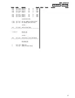
Page 17: ... 216 025 11 RES CHIP 100 5 1 10W R403 1 216 073 00 RES CHIP 10K 5 1 10W R404 1 216 073 00 RES CHIP 10K 5 1 10W VARIABLE RESISTOR RV301 1 241 763 11 RES ADJ CARBON 4 7K FREE RUN FREQ RV302 1 227 189 11 RES VAR CARBON 20K 20K VOL SWITCH S301 1 771 980 11 SWITCH TACTILE TUNE 1 678 658 11 RX SW BOARD SWITCH S302 1 572 467 61 SWITCH PUSH 1 KEY POWER ON OFF MISCELLANEOUS 6 X 3380 120 1 DRIVER ASSY 8 1 7...

Page 18: ...ump to the revised page Also clicking the version at the upper right on the revised page allows you to jump to the next revised page Ver Date Description of Revision 1 1 2001 06 Correction of electrical adjustment and electrical parts list ENG 01007 1 0 2001 05 New ...

Reviews: