


2
RM-X11M
SECTION 1
GENERAL
This section is extracted from
instruction manual.
The following buttons (except the SOURCE and MODE button) share the same functions as those on the
master unit or the wireless remote commander.
For more information about the functions of each button or control, refer to the operating instructions of your
Sony master unit equipment.
1
VOL +/– buttons
To adjust volume.
2
OFF button
To power off; stop the source.
3
GP
*
1
/ALBM
*
2
–/+ button
*
3
*
4
CD/MD:
To skip groups/albums (press); skip groups/
albums continuously (press and hold).
Radio:
To select the preset stations.
4
MODE
*
3
button
To select the radio band/select the SAT tuner
band (mode)
*
5
/select the unit
*
6
.
5
.m/M>
(SEEK (–/+)/AMS)
*
3
buttons
CD/MD:
To skip tracks (press); skip tracks continuously
(press, then press again within about 1 second
and hold); reverse/fast forward a track (press
and hold).
Radio:
To tune in stations automatically (press); find a
station manually (press and hold).
6
SOURCE button
To power on; change the source (Radio/CD/
MD
*
7
/AUX/SAT
*
5
).
*
1
When an ATRAC CD is played.
*
2
When an MP3/WMA is played.
*
3
A Cassette player can also be operated with this
remote commander.
For more information, refer to the operating
instructions of master unit.
*
4
If a changer is connected, the operation is
different. See the operating instructions of the
master unit.
*
5
When a SAT tuner is connected.(USA only)
*
6
When a CD/MD changer is connected.
*
7
When an MD changer is connected.
Location and function of controls
Installation
Notes
• Choose a mounting location carefully so that the
remote commander:
— will not interfere with driving the motorboat.
— is easy to operate.
— will not constantly get wet or dirty from sea
water, rain, dust, etc.
— is not subject to high temperatures, such as
from direct sunlight.
• Be sure to use only the supplied mounting
hardware for a safe and secure installation.
• When installing the remote commander, be sure
not to damage electrical cables, etc., on the other
side of the mounting surface.
Notes on waterproof performance
• This remote commander conforms to IEC60529
IPX6
*
1
and IPX7
*
2
, and can be used in places
exposed to splashing water or underwater up to
depths of 1 m (3 ft 3
1
/
4
in).
*
1
Water shall not enter the interior even when
exposed to direct jet streams of water (normal
temperature fresh water) from any direction.
*
2
Water shall not seep into the interior even
when left submerged in normal temperature
fresh water at a depth of 1 m (3 ft 3
1
/
4
in) in a
stationary condition for approximately 30
minutes.
• Do not use this remote commander in the
following places:
places where the remote commander might be
subject to high water pressure, hot springs or
bathtubs, etc.
Unit: mm (in)
Unité : mm (po)
Unidad: mm
Einheit: mm
Unità: mm
Eenheid: mm
VO
L
OFF
M
O
D
E
GP/A
LBM
S
OU
RC
E
VO
L
VO
L
1
Make the mounting hole as follows.
Effectuez le trou de montage de la façon suivante.
Perfore el orificio de montaje del modo siguiente.
Nehmen Sie die Montagebohrung wie folgt vor.
Praticare il foro di montaggio come indicato.
Maak als volgt het gat voor de installatie.
3
2
3 4
6
2
4
4
4
4
1
1
1
51 (2)
8
A
B
Uses bolt
1
depending on the mounting location,
and fasten them in the way of either A or B.
Utilisez le boulon
1
en fonction de l’emplacement
de montage et serrez de la façon A ou B.
Utilice pernos
1
en función de la ubicación de
montaje y apriételos en la dirección A o B.
Bringen Sie Schraube
1
je nach Montageposition an
und ziehen Sie sie wie in Abbildung A oder B
erläutert an.
Utilizzare il bullone
1
a seconda della posizione di
installazione, quindi serrare verso A o B.
Gebruik bout
1
op de juiste manier voor de
installatieplaats en draai deze vast op manier A of B.
Insert bolt
1
in the slot as shown, and turn it anticlockwise until it is secure.
Then tighten the nut
4
fully clockwise.
Insérez le boulon
1
dans la fente, ainsi qu’il est illustré, puis tournez-le dans le sens anti-
horaire jusqu’à ce qu’il soit correctement fixé.
Serrez ensuite l’écrou
4
à fond dans le sens horaire.
Inserte el perno
1
en la ranura tal y como se muestra en la ilustración y gírelo hacia la izquierda
hasta que quede fijado.
A continuación, apriete la tuerca
4
completamente hacia la derecha.
Setzen Sie Schraube
1
wie gezeigt in die Auskerbung ein und ziehen Sie sie gegen den
Uhrzeigersinn fest an.
Ziehen Sie dann die Mutter
4
im Uhrzeigersinn fest an.
Inserire il bullone
1
come illustrato, quindi ruotarlo in senso antiorario finché non è in
posizione salda.
Quindi, serrare completamente il dado
4
in senso orario.
Plaats bout
1
in de sleuf op de manier die wordt weergegeven en draai deze linksom tot de
bout goed vastzit.
Draai de moer
4
volledig naar rechts.
Insert bolt
1
in the slot as shown, and turn it clockwise until it is secure.
Then tighten the nut
4
fully clockwise.
Insérez le boulon
1
dans la fente, ainsi qu’il est illustré, puis tournez-le dans le sens horaire
jusqu’à ce qu’il soit correctement fixé.
Serrez ensuite l’écrou
4
à fond dans le sens horaire.
Inserte el perno
1
en la ranura tal y como se muestra en la ilustración y gírelo hacia la derecha
hasta que quede fijado.
A continuación, apriete la tuerca
4
completamente hacia la derecha.
Setzen Sie Schraube
1
wie gezeigt in die Auskerbung ein und ziehen Sie sie im Uhrzeigersinn
fest an.
Ziehen Sie dann die Mutter
4
im Uhrzeigersinn fest an.
Inserire il bullone
1
come illustrato, quindi ruotarlo in senso orario finché non è in posizione
salda.
Quindi, serrare completamente il dado
4
in senso orario.
Plaats bout
1
in de sleuf op de manier die wordt weergegeven en draai deze rechtsom tot de
bout goed vast zit.
Draai de moer
4
volledig naar rechts.
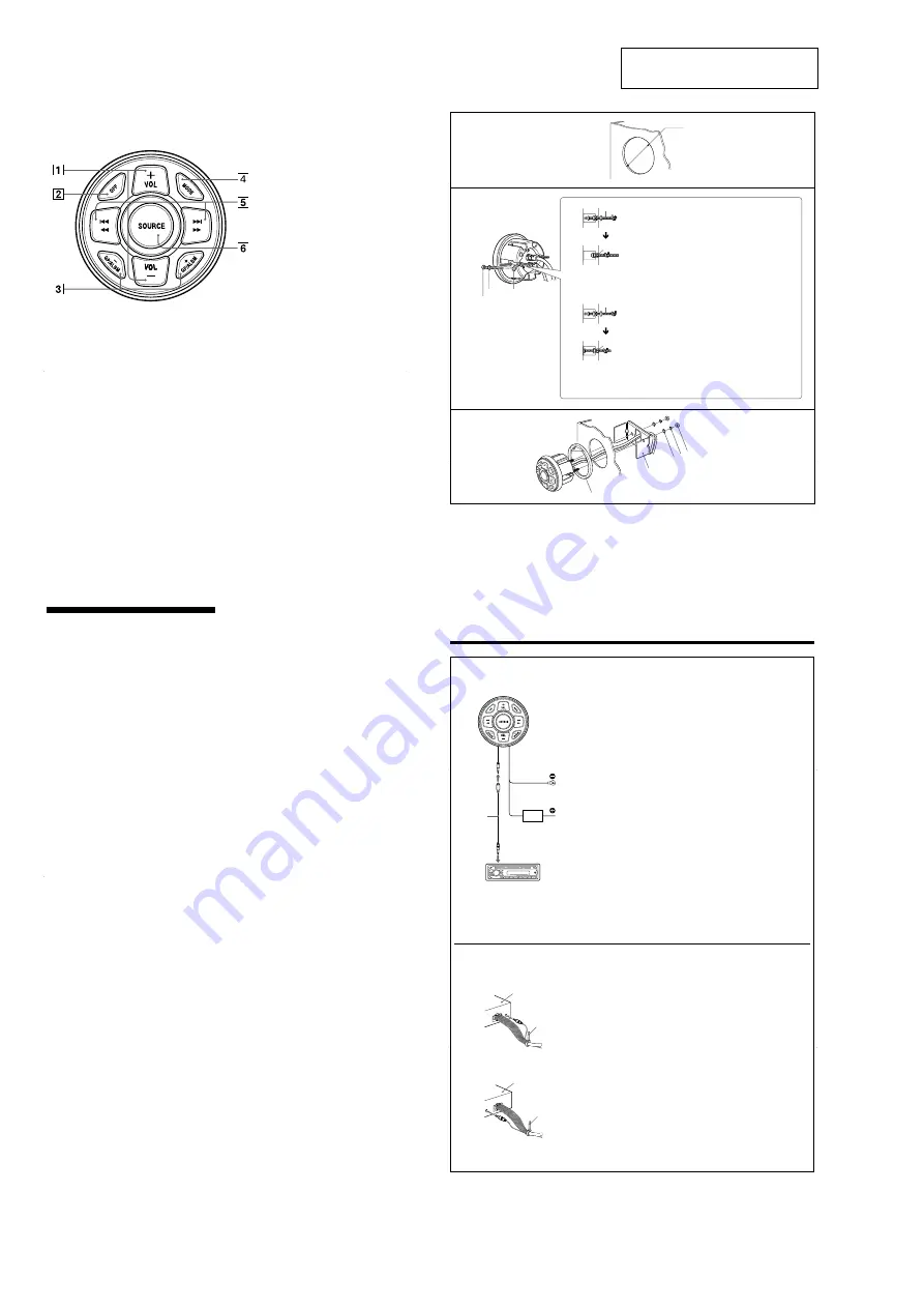
Fuse replacement
If the fuse blows, check the power connection and replace the fuse. If the fuse blows again after replacement, there
may be an internal malfunction.
Warning
Use a fuse with the specified amperage rating. Use of a higher amperage fuse may cause serious damage.
Remplacement du fusible
Si le fusible fond, verifiez le branchement de l’alimentation et remplacez le fusible. Si le nouveau fusible fond de
nouveau, il est possible que l’appareil soit defectueux.
Avertissement
Utilisez un fusible en respectant le niveau d’intensité spécifié. L’utilisation d’un fusible d’une intensité supérieure
peut provoquer des dommages.
Sustitución del fusible
Si el fusible se funde, verifique la conexion de la alimentacion y sustituyalo. Si el fusible vuelve a fundirse despues
de sustituirlo, es posible que exista algun fallo de funcionamiento interno.
Advertencia
Utilice un fusible que disponga del amperaje especificado. El uso de fusibles con un amperaje superior puede
provocar daños graves.
Austauschen der Sicherung
Wenn die Sicherung durchbrennt, überprüfen Sie den Stromanschluss und tauschen die Sicherung aus. Brennt die
neue Sicherung ebenfalls durch, kann eine interne Fehlfunktion vorliegen.
Achtung
Verwenden Sie eine Sicherung mit dem angegebenen Ampere-Wert. Bei einer Sicherung mit einem höheren Ampere-
Wert kann es zu schweren Schäden kommen.
Sostituzione del fusibile
Se il fusibile si brucia, controllare i collegamenti dell’alimentazione e sostituire il fusibile. Se dopo la sostituzione il
fusibile si brucia di nuovo, e possibile che si tratti di un problema interno.
Avvertenza
Utilizzare un fusibile con l’amperaggio specificato. L’uso di un fusibile con amperaggio superiore a quanto
specificato potrebbe provocare gravi danni.
Zekeringen vervangen
Als de zekering doorbrandt, moet u de voedingsaansluiting controleren en de zekering vervangen. Brandt de
zekering vervolgens nogmaals door, dan kan er sprake zijn van een defect in het apparaat.
Waarschuwing
Gebruik een zekering met het opgegeven vermogen. Als u een zekering gebruikt met een hoger vermogen, kan dit
ernstige beschadigingen tot gevolg hebben.
Connections/Connexions/Conexiones/Anschlüsse/Collegamenti/Aansluitingen
5
A
Master unit
Appareil principal
Unidad maestra
Hauptgerät
Unità principale
Hoofdeenheid
A
To a metal point connected to a ground on the boat
First connect the black ground lead, then connect the
orange/white power supply leads.
B
To a +12 V illumination circuit of the boat
Be sure to connect the black ground lead to it first.
Notes
• Be sure all the cords, connection plugs, and the divide box are
located and fixed in position so that they are not subjected to
high temperatures, vibration, sea water, rain, dust, etc.
• When you connect the remote commander to the master unit,
refer also to the Installation/Connections manual of the master
unit.
A
Vers un point métallique raccordé à la terre du bateau
Commencez par raccorder le câble de terre noir, puis
raccordez les câbles d’alimentation orange/blanc.
B
Vers un circuit d’éclairage du bateau de +12 V
Commencez par raccorder le câble de terre noir.
Remarques
• Veillez à ce que tous les câbles, les fiches des connexions et le
boîtier de dérivation soient situés et fixés dans une position qui
ne soit pas soumise à des températures élevées, à des vibrations,
à l’eau de mer, à la pluie, à la poussière, etc.
• Lorsque vous raccordez la telecommande a l’appareil principal,
reportez-vous egalement au guide Installation/Connexions de
l’appareil principal.
A
A un punto metálico conectado a un punto de
conexión a masa del barco
En primer lugar, conecte el cable negro de conexión a
tierra y, a continuación, conecte los cables de
alimentación naranjas/blancos.
B
A un circuito de iluminación de +12 V del barco
Asegúrese de conectar el cable negro de conexión a tierra
primero.
Notas
• Asegúrese de que todos los cables, las clavijas de conexión y la
caja de división están situados y fijados en una ubicación en la
que no estén expuestos a altas temperaturas, vibraciones, agua
marina, lluvia, polvo, etc.
• Cuando conecte el control remoto a la unidad maestra, consulte
también el manual de instalación/conexiones correspondiente.
Master unit
Appareil principal
Unidad maestra
Hauptgerät
Unità principale
Hoofdeenheid
After connecting, bundle up the connecting cords of the
remote commander with other connecting cords of the
audio equipment by attaching the supplied clamp
7
. Be
sure to leave some slack in the connecting cord between
the plug and the clamp as illustrated.
Une fois les raccordements effectués, regroupez les
câbles de raccordement de la télécommande avec les
autres câbles de raccordement de l’équipement audio à
l’aide du collier
7
fourni. Faites en sorte que les câbles
de raccordement restent lâches entre la fiche et le collier,
ainsi qu’il est illustré.
Una vez realizada la conexión, agrupe los cables de
conexión del control remoto con otros cables de
conexión del equipo de audio colocando la abrazadera
suministrada
7
. Asegúrese de dejar cierta holgura en el
cable de conexión entre la clavija y la abrazadera tal y
como se muestra en la ilustración.
7
7
To prevent plug from falling off/Pour éviter que la fiche ne tombe/Para evitar que la clavija se caiga/
So verhindern Sie, dass sich der Stecker löst/Per evitare che la spina si stacchi/Voorkomen dat de stekker losraakt
Master unit
Appareil principal
Unidad maestra
Hauptgerät
Unità principale
Hoofdeenheid
B
A
An ein an Masse auf dem Boot angeschlossenes
Metallteil
Schließen Sie zuerst die schwarze Masseleitung und dann
die orange-weiße Stromversorgungsleitung an.
B
An einen +12-V-Beleuchtungsschaltkreis des Boots
Achten Sie darauf, die schwarze Masseleitung zuerst
daran anzuschließen.
Hinweise
• Achten Sie darauf, alle Kabel, Verbindungsstecker und den
Teiler so zu verlegen und zu fixieren, dass sie vor hohen
Temperaturen, Vibrationen, Wasser, Regen, Staub usw.
geschützt sind.
• Wenn Sie die Fernbedienung an das Hauptgerät anschließen,
schlagen Sie bitte auch in der Installations-/Anschlussanleitung
zum Hauptgerät nach.
A
Ad un punto metallico collegato alla massa
sull’imbarcazione
Collegare innanzitutto il cavo di massa nero, quindi
collegare i cavi di alimentazione arancione/bianchi.
B
A un circuito di illuminazione da +12 V dell’imbarcazione
Accertarsi di collegare prima il cavo di massa nero.
Note
• Accertarsi che tutti i cavi, le spine di collegamento e la divide
box siano posizionati e fissati in luoghi non soggetti a
temperature elevate, vibrazioni, acqua di mare, pioggia,
polvere e così via.
• Quando il telecomando viene collegato all’unità principale,
consultare inoltre il manuale di installazione/dei collegamenti
dell’unità principale.
A
Naar een metalen punt dat is aangesloten op een
aardingspunt op de boot
Sluit eerst de zwarte aardingskabel aan en vervolgens de
oranje/witte voedingskabel.
B
Naar een +12 V-verlichtingscircuit op de boot
Sluit de zwarte aardingskabel er eerst op aan.
Opmerkingen
• Zorg ervoor dat alle snoeren, stekkers en de verdeeldoos op een
plaats zijn vastgemaakt waar ze niet worden blootgesteld aan
hoge temperaturen, trillingen, zeewater, regen, stof enzovoort.
• Als u de afstandsbediening aansluit op de hoofdeenheid, moet
u ook de gebruiksaanwijzing voor installatie/aansluitingen van
de hoofdeenheid raadplegen.
Nachdem Sie die Anschlüsse vorgenommen haben,
bündeln Sie die Verbindungskabel der Fernbedienung
und der Audiogeräte mithilfe des mitgelieferten
Kabelbinders
7
. Lassen Sie das Verbindungskabel
zwischen dem Stecker und dem Kabelbinder unbedingt
etwas durchhängen, wie in der Abbildung gezeigt.
A collegamento completato, unire i cavi di collegamento
del telecomando con gli altri cavi di collegamento
dell’apparecchiatura audio utilizzando l’apposito fermo
7
in dotazione. Accertarsi di lasciare lievemente
allentato il cavo di collegamento tra la spina e il fermo,
come illustrato.
Nadat u de afstandsbediening hebt aangesloten,
bevestigt u de bijgeleverde klem
7
om de
aansluitsnoeren van de afstandsbediening met de
andere aansluitsnoeren van de audioapparatuur te
bundelen. Zorg ervoor dat het aansluitsnoer tussen de
stekker en de klem enigszins slap hangt, zoals in de
afbeelding wordt weergegeven.
Fuse (1A)


