background image

Using the Menu


16

The setting items (icons) in the selected menu are 
displayed in yellow.

4

Press the 

M

 or 

m

 button to select “LANGUAGE,” 

then press the 

,

 or ENTER button.

The selected item is displayed in yellow.

5

Press the 

M

 or 

m

 button to select a language, then 

press the 

,

 or ENTER button.

The menu changes to the selected language.

To clear the menu

Press the MENU button.
The menu disappears automatically if a button is not 
pressed for one minute.

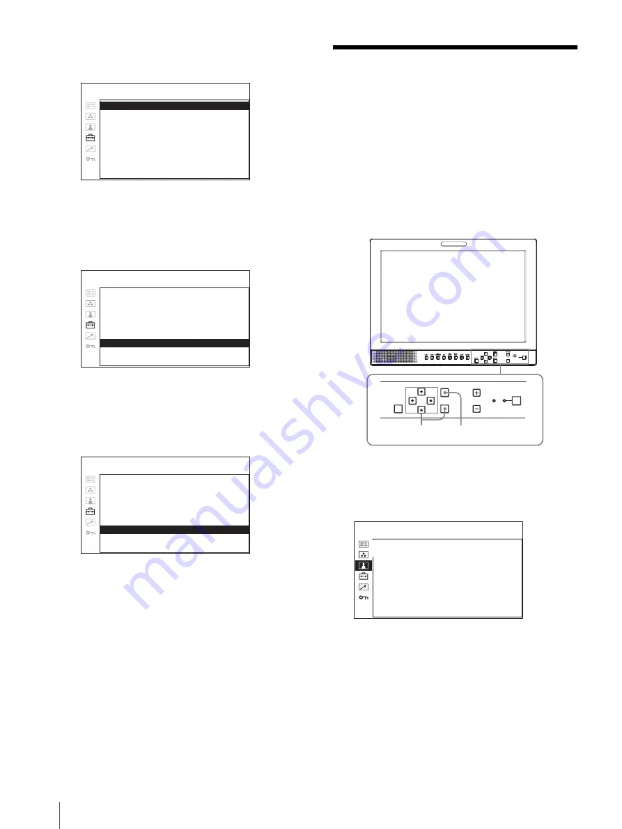
Using the Menu

The unit is equipped with an on-screen menu for making 
various adjustments and settings such as picture control, 
input setting, set setting change, etc.  You can also 
change the menu language displayed in the on-screen 
menu.

To change the menu language, see “Selecting the Menu 
Language” on page 15.

The current settings are displayed in place of the 

x


marks on the illustrations of the menu screen.

1

Press the MENU button.

The menu appears.
The menu presently selected is shown in yellow.

2

Press the 

M

 or 

m

 button to select a menu, then press 

the 

,

 or ENTER button.

The menu icon presently selected is shown in 
yellow and setting items are displayed.

R G B / C O M P   S E L :  

xxxx

xxx

C O M P O N E N T   L E V E L :


xxx

xxxx

N T S C   S E T U P :  

xxxxxx

x

S C A N :  

xx

xxxxx 

G A M M A :  

xxxx

xxx

F O R M AT   D I S P L AY:  

xxx

xxxx

L A N G U A G E :  

xx

ENGLISH

B A C K G R O U N D :  

xxxxx

xx

I / P   M O D E :  

xxxx

xxx

USER CONFIG – SYSTEM SETTING 1/2

R G B / C O M P   S E L :


xxxx

xxx

C O M P O N E N T   L E V E L :


xxx

xxxx

N T S C   S E T U P :  

xxxxxx

x

S C A N :  

xx

xxxxx 

G A M M A :  

xxxx

xxx

F O R M AT   D I S P L AY:  

xxx

xxxx

L A N G U A G E :


x

E N G L I S H

B A C K G R O U N D :  

xxxxx

xx

I / P   M O D E :  

xxxx

xxx

USER CONFIG – SYSTEM SETTING 1/2

R G B / C O M P   S E L :


x

xx

C O M P O N E N T   L E V E L :  

xxxxx

N T S C   S E T U P :  

x

S C A N :  

xxxxxx 

G A M M A :  

xx

F O R M AT   D I S P L AY:  

xx

L A N G U A G E :


E N G L I S H

B A C K G R O U N D :  

xx

I / P   M O D E :  

x

USER CONFIG – SYSTEM SETTING 1/2

RESET

MENU

VOLUME

KEY

INHIBIT

ENTER

1

1

2~4

1

C O N T R O L  
  C O N T R A S T :


xx

  B R I G H T N E S S :  

xx

  C H R O M A :  

xx

  P H A S E :  

xx

  A P E R T U R E :  

x

  B A C K L I G H T :  

x

USER CONTROL

Summary of Contents for LMD-1510W

Page 1: ...LCD Monitor Operating Instructions Before operating the unit please read this manual thoroughly and retain it for future reference LMD 1510W 4 281 153 11 1 2011 Sony Corporation ...

Page 2: ...ng to qualified service personnel Servicing is required when the apparatus has been damaged in any way such as power supply cord or plug is damaged liquid has been spilled or objects have fallen into the apparatus the apparatus has been exposed to rain or moisture does not operate normally or has been dropped WARNING To reduce the risk of fire or electric shock do not expose this apparatus to rain...

Page 3: ...can radiate radio frequency energy and if not installed and used in accordance with the instruction manual may cause harmful interference to radio communications Operation of this equipment in a residential area is likely to cause harmful interference in which case the user will be required to correct the interference at his own expense You are cautioned that any changes or modifications not expre...

Page 4: ...s product contains mercury Disposal of these materials may be regulated due to environmental considerations For disposal or recycling information please contact your local authorities or the Telecommunications Industry Association www eiae org ...

Page 5: ...ols 9 Front Panel 9 Input Signals and Adjustable Setting Items 10 Rear Panel 11 Installing to the Rack 12 Connecting the AC Power Cord 13 Attaching the Input Adaptor 13 Selecting the Default Settings 14 Selecting the Menu Language 15 Using the Menu 16 Adjustment Using the Menus 17 Items 17 Adjusting and Changing the Settings 18 STATUS menu 18 COLOR TEMP BAL menu 18 USER CONTROL menu 19 USER CONFIG...

Page 6: ...D monitor s screen Do not place a heavy object on the LCD monitor s screen This may cause the screen to lose uniformity If the unit is used in a cold place horizontal lines or a residual image may appear on the screen This is not a malfunction When the monitor becomes warm the screen returns to normal The screen and the cabinet become warm during operation This is not a malfunction On Burn in For ...

Page 7: ...et is in contact with a rubber or vinyl resin product for a long period of time the finish of the cabinet may deteriorate or the coating may come off On Moisture Condensation If the unit is brought directly from a cold place to a warm place or the unit is warm and the ambient temperature cools suddenly by air conditioning for example moisture may condense on the surface or inside of the unit or cr...

Page 8: ...gnal aspect etc by operating the equipment connected to the PARALLEL REMOTE connector Monitor stand with tilt function A monitor stand with tilt function is equipped for desk top use It shall be removed when mounted on the rack Rack mount The monitor supports the VESA 100 100 mm standard It can be mounted on an EIA standard 19 inch rack using an optional mounting bracket For more information see I...

Page 9: ...previous value This button functions when the menu item is adjusted displayed on the screen ENTER button Press to confirm a selected item on the menu f ASPECT select button Sets the aspect ratio of the picture 4 3 or 16 9 g SCAN select button You can change the scan size of the picture Press to change the scan size among over 5 over scan normal 0 scan and full screen set on the SCAN menu page 20 h...

Page 10: ...al is input this can be switchable 4 When BKM 320D or BKM 341HS is used SDI signals can be input 5 When a PC signal is input to the HDMI IN connector using a DVI conversion cable this can be adjusted Input signal Item Video Y C B W Component RGB SDI 4 HDMI SD HD SD HD SD HD SD HD DVI 5 CONTRAST a a a a a a a a a a BRIGHT a a a a a a a a a a CHROMA a a a a a a PHASE a NTSC APERTURE a a a a a a a a ...

Page 11: ...ess the EXT SYNC button to use the sync signal through this connector IN connector When this unit operates on an external sync signal connect the reference signal from a sync generator to this connector Note When inputting a video signal with the jitters etc the picture may be disturbed We recommend using the TBC time base corrector OUT connector Loop through output of the IN connector Connect to ...

Page 12: ...e signal input through these connectors If you input signals to both Y C IN and VIDEO IN the signal input to the Y C IN is selected Y C IN OUT 4 pin mini DIN These are the input output connectors for a Y C separate signal Connect them to the Y C separate input output connectors on equipment such as a VCR video camera or another monitor VIDEO IN OUT BNC These are the input output connectors for a c...

Page 13: ...ocks To disconnect the AC power cord Pull out the AC plug holder while pressing the lock levers Attaching the Input Adaptor Before attaching the input adaptor disconnect the power cord BKM 320D BKM 341HS Note Do not connect the equipment other than BKM 320D or BKM 341HS It causes damage to the unit or the equipment LINE VIDEO IN OUT AUDIO IN OUT AC power cord AC IN socket AC plug holder Supplied L...

Page 14: ...rther and then press the or ENTER button The confirmation screen is displayed Confirm the selected area When the setting is wrong press the button to return to the previous screen 3 3 4 5 3 1 2 COLOR TEMP COMPONENT LEVEL NTSC SETUP 1NORTH AMERICA LOW BETA7 5 7 5 2LATIN AMERICA PAL PAL N AREA ARGENTINA LOW SMPTE 0 PARAGUAY LOW SMPTE 0 URUGUAY LOW SMPTE 0 NTSC PAL M AREA OTHER AREA LOW BETA7 5 7 5 3...

Page 15: ...rench German Spanish Italian Japanese Chinese for displaying the menu and other on screen displays ENGLISH English is selected in the default setting The current settings are displayed in place of the x marks on the illustrations of the menu screen 1 Press the 1 standby switch to turn on the unit 2 Press the MENU button The menu appears The menu presently selected is shown in yellow 3 Press the M ...

Page 16: ...he x marks on the illustrations of the menu screen 1 Press the MENU button The menu appears The menu presently selected is shown in yellow 2 Press the M or m button to select a menu then press the or ENTER button The menu icon presently selected is shown in yellow and setting items are displayed RGB COMP SEL xxxxxxx COMPONENT LEVEL xxxxxxx NTSC SETUP xxxxxxx SCAN xxxxxxx GAMMA xxxxxxx FORMAT DISPL...

Page 17: ...22 To clear the menu Press the MENU button The menu disappears automatically if a button is not pressed for one minute About the memory of the settings The settings are automatically stored in the monitor memory To reset items that have been adjusted Pressing the RESET button while you are adjusting any of the menu items resets the menu item to the previous setting Adjustment Using the Menus Items...

Page 18: ...re Model name and serial number Option COLOR TEMP BAL menu The COLOR TEMP BAL menu is used for adjusting the picture white balance You need to use the measurement instrument to adjust the white balance Recommended Konica Minolta color analyzer CA 210 FORMAT xxxxxxxxx xxxxxxxx COLOR TEMP xxx GAMMA xx COMPONENT LEVEL xxxxx NTSC SETUP x RGB COMP SEL xx SCAN MODE xxxxxxxx STATUS 1 2 LMD 1510W xxxxxxx ...

Page 19: ... the setting the lower the intensity PHASE Adjusts color tones The higher the setting the more greenish the picture The lower the setting the more purplish the picture APERTURE Adjusts the picture sharpness The higher the setting the sharper the picture The lower the setting the softer the picture BACKLIGHT Adjusts the backlight When the setting is changed the brightness of the backlight is change...

Page 20: ...elay by the picture processing to the minimum level when the signal is input INTER FIELD Performs interpolation depending on the movement of the images between the fields It takes longer than LINE DOUBLER for processing the picture INTER FIELD is the factory setting LINE DOUBLER The processing time is shorter Performs interpolation by repeating each line in the data receiving sequence regardless o...

Page 21: ... the film When 16 9 aspect ratio is selected with the ASPECT select button You can select either 4 3 or OFF When 4 3 aspect ratio is selected with the ASPECT select button You can select either 16 9 or OFF 4 3 16 9 Output 4 3 16 9 4 3 16 9 4 3 MARKER ENABLE xxx MARKER SELECT xxx CENTER MARKER xx SAFETY AREA xxx MARKER LEVEL x USER CONFIG MARKER SETTING CENTER MARKER Select ON to display the center...

Page 22: ...isplayed in black indicating the items are locked Troubleshooting This section may help you isolate the cause of a problem and as a result eliminate the need to contact technical support The display is colored in green or purple t Select the correct input from the RGB COMP SEL setting in the USER CONFIG menu page 19 The unit cannot be operated t The key protection function works Set the KEY INHIBI...

Page 23: ...c terminal function VIDEO output BNC type 1 Loop through with 75 Ω automatic terminal function AUDIO output Phono jack 1 Loop through RGB COMPONENT output connectors RGB Component output BNC type 3 Loop through with 75 Ω automatic terminal function AUDIO output Phono jack 1 Loop through External synchronized output connector BNC type 1 Loop through with 75 Ω automatic terminal function Built in sp...

Page 24: ...ys verify that the unit is operating properly before use SONY WILL NOT BE LIABLE FOR DAMAGES OF ANY KIND INCLUDING BUT NOT LIMITED TO COMPENSATION OR REIMBURSEMENT ON ACCOUNT OF THE LOSS OF PRESENT OR PROSPECTIVE PROFITS DUE TO FAILURE OF THIS UNIT EITHER DURING THE WARRANTY PERIOD OR AFTER EXPIRATION OF THE WARRANTY OR FOR ANY OTHER REASON WHATSOEVER Pin number Functions 1 Designating LINE input ...

Page 25: ...e 16 9 4 3 ITU R BT 1358 480 60P 525 483 60 Progressive 16 9 4 3 SMPTE 293M 1080 24P 1 1125 1080 24 Progressive 16 9 SMPTE 274M 1080 25P 1125 1080 25 Progressive 16 9 SMPTE 274M 1080 30P 1 1125 1080 30 Progressive 16 9 SMPTE 274M 1080 50I 1125 1080 25 2 1 interlace 16 9 SMPTE 274M 1080 60I 1 1125 1080 30 2 1 interlace 16 9 SMPTE 274M BTA S 001B 720 50P 750 720 50 Progressive 16 9 SMPTE 296M 720 60...

Page 26: ...Rear Side Bottom Mass Approx 5 8 kg 12 lb 13 oz 1 378 15 124 9 5 155 7 6 1 4 200 7 8 2 5 1 8 100 4 15 19 32 100 4 75 2 3 90 35 8 96 8 37 8 67 7 2 3 4 264 4 101 2 204 3 81 8 165 1 61 2 216 4 85 8 4 M5 76 2 3 114 6 4 5 8 Unit mm inches ...

Page 27: ...Sony Corporation ...

Reviews: