background image

– 8 –

KV
-G21M2

RM-869

Operations

10

-EN

Adjusting the
picture

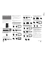
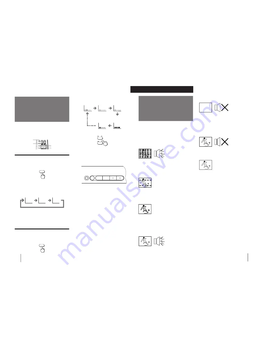
Each time you press SELECT, the screen changes as
follows:

2

Press +/– to adjust the item.

3

To adjust other items, repeat steps 1 and 2.

Note

You can also use SELECT and 

.


+/– on the TV to adjust the

picture setting.

If the picture color is abnormal when receiving
programs through the 

˘

 (antenna) terminal

Change the “TV SYSTEM” or “COLOR SYSTEM”
setting or adjust the “COLOR” level in the on-screen
display until the color becomes normal.

If the picture is abnormal when receiving
programs through the 

 (video input) jack

Change the “COLOR SYSTEM” setting or adjust the
“COLOR” level in the on-screen display until the color
becomes normal.

Note

Normally set “COLOR SYSTEM” to “AUTO”.

If the sound is distorted or noisy when
receiving programs through the 

˘

 (antenna)

terminal

Change the “TV SYSTEM” setting in the on-screen
display until the sound becomes clear.

Note on the SOUND MODE button

The sound mode feature is unavailable for your TV. Thus, the
SOUND MODE button on the remote commander is not used
for your TV.

Selecting the picture mode

Press PIC MODE until the mode you want
appears.

Each time you press PIC MODE, the screen changes as
follows:

Note

If you change the picture mode after the following
adjustments, the adjustment changes in accordance with the
picture mode.

Adjusting the picture setting

1

Press SELECT until the item you want to
adjust appears.

÷

0

SOUND

MODE

SELECT
PIC MODE

PIC MODE

High contrast
picture

Soft picture
(good for video
games)

DYNAMIC

STANDARD

SOFT

+/–

SELECT

PICTURE

COLOR

BRIGHT

HUE

SHARPNESS

(Operative for
NTSC signal
only)

SELECT

–      

PROGR

      +


.

      +

Front of TV

Normal
picture

Additional Information

11

-EN

Troubleshooting

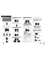
No picture
No sound

/

Press 

U

 or 

u

.

/

Check the antenna connection.

/

Check the VCR connections.

/

Check the power cord connection.

/

Check the standby mode.

Good picture
No sound

/

Press 

.

 +.

/

Press 

¤

.

No color

/

Adjust the “COLOR” level in the on-
screen display.

/

Check the “COLOR SYSTEM” setting.

TV cabinet creaks

/

Even if the picture or the sound is normal,
changes in the room temperature
sometimes make the TV cabinet expand or
contract, making a noise. This does not
indicate a malfunction.

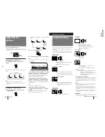
Note on the remote commander

The supplied remote commander is used on several models of
the TV.  If you do not find instructions for some controls that
are on the remote commander, that means your TV does not
employ the features of those controls, e.g. 

L

 and SOUND

MODE.

Notes

When you turn on the TV, you may hear the “boon” sound
that is caused by the demagnetization of the TV. This does not
indicate a malfunction.

The picture color may become abnormal if you change the
direction of your TV. To obtain the normal picture color, press

U

 on the TV to turn off the TV for five minutes and then turn

it on again.

Design and specifications are subject to change without notice.

All contents in the instruction manual are subject to change
without notice.

WARNING

Do not install the appliance in a confined space, such as
a bookcase or built-in cabinet.

If you have any problems, read this manual again and
check the countermeasure for each of the symptoms
listed below.
If the problem persists after trying the methods below,
contact your nearest authorized service center or dealer.

Snowy picture
Noisy sound

/

Check the antenna.

/

Check the antenna connection on the TV
and on the wall.

/

Check the “TV SYSTEM” setting.

Dotted lines or stripes

/

This may be caused by local interference
(e.g. cars, neon signs and hair dryers).
Adjust the antenna for minimum interference.

Double images or “ghosts”

/

This may be caused by reflections from
nearby mountains or buildings. A highly
directional antenna may improve the
picture.

Good picture
Noisy sound

/

Check the “TV SYSTEM” setting.

Additional Information

Summary of Contents for KV-G21M2

Page 1: ...MODEL COMMANDER DEST CHASSIS NO MODEL COMMANDER DEST CHASSIS NO KV G21M2 RM 869 Russia SCC U11B A SERVICE MANUAL BG 2S CHASSIS TRINITRON COLOR TV ...

Page 2: ...500 mVrms high impedance Outputs A earphone jack minijack Ú monitor output jacks phono jacks D video 1 Vp p 75 ohms audio 500 mVrms Picture tube 21 in Tube size cm 54 Measured diagonally Screen size cm 51 Measured diagonally Dimensions w h d mm 516 464 478 Mass kg 22 Design and specifications are subject to change without notice SPECIFICATIONS CAUTION SHORT CIRCUIT THE ANODE OF THE PICTURE TUBE AN...

Page 3: ...nt 14 3 4 G2 Screen and White Balance Adjustments 15 4 SELF DIAGNOSIS FUNCTION 16 5 CIRCUIT ADJUSTMENTS 5 1 Adjustments with Commander 17 5 2 Adjustment Method 18 5 3 A Board Adjustment after IC003 Memory Replacement 21 5 4 Picture Distortion Adjustment 21 6 DIAGRAMS 6 1 Block Diagram 23 6 2 Circuit Boards Location 26 6 3 Schematic Diagrams and Printed Wiring Boards 26 1 Schematic Diagrams of A an...

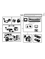
Page 4: ...ating instructions mentioned here are partial abstracts from the Operating Instructions Manual The page numbers of the Operating Instruction Manual remain as in this manual 3 1 PROGR SELECT PROGR VOLUME TV VIDEO SELECT VHF LOW B G 1 2 3 1 2 Ú Ú D ...

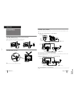
Page 5: ...to video and audio outputs VCR to antenna socket Ú D Signal flow Front of TV Camcorder D to video and audio outputs Signal flow to video input D video and audio inputs to Ú monitor output D video and audio outputs to video input D video and audio inputs When recording through the Ú monitor output jack Do not change the channel or video input while recording with a VCR otherwise the channel or vide...

Page 6: ...ted EN 5 Press on the remote commander or on the TV again To start presetting channels automatically from the specified program position Press PROGR or number buttons on the remote commander or PROGR on the TV until the required program position appears on the screen after step 4 of Presetting channels automatically Presetting channels manually 1 Press SELECT on the remote commander or the TV unti...

Page 7: ...F SLEEP TIMER 90M C I Displaying on screen information Press E G The program position local system and TV settings are displayed on the screen E G Setting the Sleep Timer You can set the TV automatically turned off as you program Press C I To cancel the Sleep Timer press C I repeatedly until SLEEP TIMER OFF appears or turn off the TV Changing the on screen display language You can use buttons on t...

Page 8: ...nections Check the power cord connection Check the standby mode Good picture No sound Press Press No color Adjust the COLOR level in the on screen display Check the COLOR SYSTEM setting TV cabinet creaks Even if the picture or the sound is normal changes in the room temperature sometimes make the TV cabinet expand or contract making a noise This does not indicate a malfunction Note on the remote c...

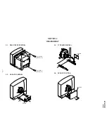
Page 9: ...V G21M2 RM 869 2 1 REAR COVER REMOVAL 2 2 A BOARD REMOVAL 2 4 SERVICE POSITION SECTION 2 DISASSEMBLY Four screws BVTP 4 16 1 2 Two screws BVTP 4 16 Lever Lever A board 2 3 F1 BOARD REMOVAL A board F1 board ...

Page 10: ...LACEMENT OF MULTI BUTTON 2 6 TERMINAL BOARD BRACKET REMOVAL 2 7 DEMAGNETIZATION COIL REMOVAL Two claws A board Terminal board bracket A board Terminal board bracket 1 Demagnetization coil 2 Tension spring Picture tube Cut Cut Multi button Multi button Three screws BVTP 3 12 SCREWING TORQUE 7 1 kg cm 2 5 2 REPLACEMENT OF LIGHT GUIDE Light guide Cut Cut Light guide Two screws BVTP 3 12 SCREWING TORQ...

Page 11: ...he rubber too hard so as not to damage the inside of anode cap A metal fitting called the shatter hook terminal is built into the rubber 3 Do not turn the foot of rubber over too hard The shatter hook terminal will stick out or damage the rubber REMOVAL OF ANODE CAP NOTE After removing the anode short circuit the anode of the picture tube and the anode cap to the metal chassis CRT shield or carbon...

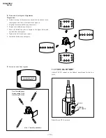
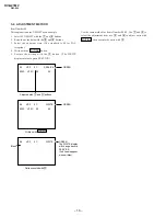
Page 12: ... and degauss with the degausser 3 1 BEAM LANDING 1 Input a white signal with the pattern generator Contrast Brightness 2 Set the pattern generator raster signal to green 3 Move the deflection yoke to the rear and adjust with the purity control so that the green is at the center and the blue and the red take up equally sized areas on each side See Figures 3 1 through 3 3 4 Move the deflection yoke ...

Page 13: ...ng Adjustment 1 Moving vertically adjust the V STAT magnet so that the red green and blue dots are on top of each other at the center of the screen 2 Moving horizontally adjust the H STAT VR so that the red green and blue dots are on top of each other at the center of the screen 3 2 CONVERGENCE Preparation Before starting this adjustment adjust the focus horizontal size and vertical size Minimize ...

Page 14: ...Slightly loosen the deflection yoke screws 2 Remove the deflection yoke spacer 3 Move the deflection yoke as shown in the figure below and optimize the convergence 4 Tighten the deflection yoke screws 5 Install the deflection yoke spacer B G R B G R R G B R G B R G B R G B B G R B G R R G B B G R B G R R G B a d screen corner misconvergence b a c d a d c b a to d Permalloy assembly Fix a Permalloy...

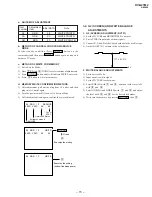
Page 15: ...al DATA 28 20 20 3 4 G2 SCREEN AND WHITE BALANCE ADJUSTMENTS 1 G2 SCREEN ADJUSTMENT RV701 1 Set the PICTURE and BRIGHTNESS to normal 2 Put to VIDEO input mode without signals 3 Connect R G and B of the C board cathode to the oscilloscope 4 Adjust G2 RV701 volume to the value below Item number 09 0A 0B Adjustment Item RDR GDR BDR 177 2 V DC 2 WHITE BALANCE ADJUSTMENTS 1 Set to Service Mode 2 Input ...

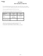
Page 16: ...60ss each time The flickering frequency responding to each failed device is shown below SECTION 4 SELF DIAGNOSIS FUNCTION Board name Ref No Device Flickering Frequency A Board IC003 NONVOLATILE MEMORY ST24C04FB6 1 A Board IC300 Y C JUNGLE TDA8375A 3 All the devices are checked one after another from the left of the table If an error is found the responding LED will start flickering So if more than...

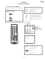
Page 17: ...he values in memory 8 All user control goes to the standard state 5 Service data initialization Be sure not to use usually 2 Write 50Hz adjustment data to 60Hz or viceversa The screen display is 1 4 Select the adjustment item 3 6 Raise lower the data MUTING Writes Executes the writing RM 869 SERVICE Mode 08 Data HSF 50 Depends on the signals PAL SECAM 50 NTSC 60 Adjustment item 00 Mode Item 00 V3 ...

Page 18: ...ecuted with 0 GREEN The WRITE display will change back to SERVICE 2nd line disappear when written 0C VSF 08 00 V3 2C 052S 00 V3 2C 052S Blank 5 2 ADJUSTMENT METHOD Item Number 08 This explanation uses V SHIFT as an example 1 Select 08 V SHIFT with the 1 and 4 buttons 2 Raise lower the data with the 3 and 6 buttons 3 Select the optimum state The standard is 0F for PAL reception 4 Write with the MUT...

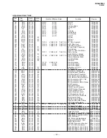
Page 19: ...l Threshold MSP3410D 1F WLL 00 FF 05 W G Monaural Threshold MSP3410D 20 ACG 00 01 01 ACG Switch auto constant MSP3410D 21 CDB 00 3F 28 ACG Gain at Constant Mode MSP3410D 22 FGP 00 7F 24 FM Prescale for B G I DK MSP3410D 23 FMP 00 7F 40 FM Prescale for M MSP3410D 24 FMH 00 7F 20 FM Prescale for HDEV Mode MSP3410D 25 WGP 00 7F 3C W G Prescale MSP3410D 26 NIP 00 7F 7F NICAM Prescale MSP3410D 27 SCP 0...

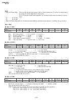
Page 20: ... 0 2 AV input model 1 1 2 AV input and RGB input model No TOP for teletext model 1 only FLOF available 0 both FLOF and TOP available AV MUT 1 AV multi is always muted if no signal input 0 not muted always Other optional bits are effective if set to 1 Item No 3F OP1 Item No NICAM HDEV 1 V Curve XTAL SEL SECAM 2nd Lang Initial data 0 0 0 0 1 1 1 1 XTAL SEL 0 0 only 4 43 XTAL 0 1 only 3 58 XTAL 1 0 n...

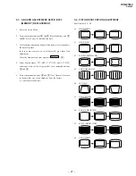
Page 21: ...rmal picture In case some items are not well adjusted give them fine adjustment Write the data per each item number MUTING 4 Select item numbers 3E OP0 3F OP1 and 40 OP2 and respectively set the bit per model with command buttons 3 and 6 5 Press commander buttons 8 and Test Normal to return to the data that was set on shipment from the factory Cancel Service Mode 00 HSF H SHIFT 01 HSZ H SIZE 02 PA...

Page 22: ... 22 KV G21M2 RM 869 MEMO ...

Page 23: ...R AC CORD 27 1 574 062 11 CORD POWER WITH CONNECTOR 2 5A 250V 28 1 452 032 00 MAGNET DISC 29 4 051 736 12 PIECE A 90 CONV CORRECT 30 4 302 404 03 SCREW WASHER HEAD P 4X16 31 1 900 212 58 LEAD ASSY FOCUS 32 3 704 372 11 HOLDER HV CABLE REF NO PART NO DESCRIPTION REMARK FOR F35821806 F35821896 1 X 4034 816 2 BEZNET ASSY 2 3 2 4 059 721 01 BUTTON MULTI 3 4 059 714 01 PLATE GUIDE LIGHT 4 1 505 740 11 ...

Page 24: ...2MF 20 50V F35430106 F35430196 ONLY C234 1 126 967 11 ELECT 47MF 20 16V C235 1 104 665 11 ELECT 100MF 20 16V C236 1 104 666 11 ELECT 220MF 20 25V F35430106 F35430196 C236 1 124 484 11 ELECT 220MF 20 35V F35821806 F35821896 C237 1 104 665 11 ELECT 100MF 20 16V C238 1 136 167 00 FILM 0 15MF 5 50V C241 1 126 942 61 ELECT 1000MF 20 25V C242 1 164 232 11 CERAMIC CHIP 0 01MF 10 50V C243 1 126 964 11 ELE...

Page 25: ...001MF 10 500V C854 1 124 480 11 ELECT 470MF 20 25V C856 1 162 318 11 CERAMIC 0 001MF 10 500V C857 1 136 159 00 FILM 0 033MF 5 50V C860 1 102 228 00 CERAMIC 470PF 10 500V C861 1 107 654 11 ELECT 33MF 20 250V C875 1 128 562 11 ELECT 47MF 20 100V C876 1 107 369 11 MYLAR 0 068MF 10 100V C891 1 163 007 11 CERAMIC CHIP 680PF 10 50V C898 1 137 150 11 MYLAR 0 01MF 10 100V C900 1 163 133 00 CERAMIC CHIP 47...

Page 26: ... DIODE RD4 7ESB2 FERRITE BEAD FB101 1 410 397 21 FERRITE 1 1UH FB102 1 410 397 21 FERRITE 1 1UH FB103 1 410 397 21 FERRITE 1 1UH FB601 1 410 397 21 FERRITE 1 1UH FB603 1 410 397 21 FERRITE 1 1UH FB610 1 410 397 21 FERRITE 1 1UH FB612 1 410 397 21 FERRITE 1 1UH FB801 1 410 397 21 FERRITE 1 1UH IC IC001 8 752 891 61 IC CXP85220A 060S IC002 8 759 805 37 IC L78LR05D MA IC003 8 759 370 33 IC ST24C04FB6...

Page 27: ...417 8 729 424 67 TRANSISTOR UN2216 F35430106 F35430196 Q417 8 729 027 56 TRANSISTOR DTC143TKA T146 F35821806 F35821896 Q418 8 729 424 67 TRANSISTOR UN2216 F35430106 F35430196 Q418 8 729 027 56 TRANSISTOR DTC143TKA T146 F35821806 F35821896 Q561 8 729 200 17 TRANSISTOR 2SA1091 O Q801 8 729 140 50 TRANSISTOR 2SC3209LK Q802 8 729 821 87 TRANSISTOR 2SD1878 CA Q821 8 729 209 15 TRANSISTOR 2SD2012 Q902 8...

Page 28: ...K 5 1 10W R266 1 216 073 00 RES CHIP 10K 5 1 10W R301 1 216 073 00 RES CHIP 10K 5 1 10W R302 1 216 063 91 RES CHIP 3 9K 5 1 10W R303 1 216 025 91 RES CHIP 100 5 1 10W R304 1 216 025 91 RES CHIP 100 5 1 10W R305 1 216 025 91 RES CHIP 100 5 1 10W R306 1 216 025 91 RES CHIP 100 5 1 10W R307 1 216 025 91 RES CHIP 100 5 1 10W R308 1 216 033 00 RES CHIP 220 5 1 10W R309 1 216 033 00 RES CHIP 220 5 1 10W...

Page 29: ...6 057 00 RES CHIP 2 2K 5 1 10W R804 1 216 049 91 RES CHIP 1K 5 1 10W R805 1 216 081 00 RES CHIP 22K 5 1 10W R809 1 247 756 11 CARBON 2 2K 5 1 2W F R811 1 216 343 00 METAL OXIDE 0 33 5 1W F R812 1 216 075 00 RES CHIP 12K 5 1 10W R816 1 249 435 11 CARBON 33K 5 1 4W R820 1 216 655 11 METAL CHIP 1 5K 0 50 1 10W R821 1 215 911 11 METAL OXIDE 100 5 3W F R822 1 216 429 00 METAL OXIDE 270 5 1W F R823 1 24...

Page 30: ...532 21 SWITCH TACTILE F35430106 F35430196 S906 1 692 431 21 SWITCH TACTILE F35821806 F35821896 SPARK GAP SG801 1 519 422 11 GAP SPARK SURFACE WAVE FILTER SWF401 1 760 771 11 FILTER SURFACE WAVE TRANSFORMER T601 1 429 137 21 TRANSFORMER CONVERTER SRT T605 1 424 682 11 TRANSFORMER LINE FILTER T801 1 437 195 11 TRANSFORMER HORIZONTAL DRIVE T851 1 453 250 11 TRANSFORMERASSY FLYBACK NX 1746 M3A THERMIS...

Page 31: ... R719 1 215 480 00 METAL 300K 1 1 4W R720 1 249 923 11 CARBON 1K 5 1 4W F R721 1 215 489 00 METAL 680K 1 1 4W R722 1 249 923 11 CARBON 1K 5 1 4W F R723 1 215 479 00 METAL 270K 1 1 4W R724 1 249 923 11 CARBON 1K 5 1 4W F R725 1 249 419 11 CARBON 1 5K 5 1 4W R726 1 249 419 11 CARBON 1 5K 5 1 4W R727 1 249 419 11 CARBON 1 5K 5 1 4W R728 1 249 407 11 CARBON 150 5 1 4W R729 1 249 408 11 CARBON 180 5 1 ...

Page 32: ...TRUCTION 4 063 784 01 INDIVIDUAL CARTON 4 063 797 01 CUSHION RIGHT LOWER 4 063 802 01 CUSHION UPPER ASSY 4 063 803 01 CUSHION LOWER ASSY 4 063 804 01 CUSHION LEFT UPPER 4 063 805 01 CUSHION RIGHT UPPER 4 063 806 01 CUSHION LEFT LOWER 4 392 003 11 BAND HOLD 4 392 004 11 CLIP 4 395 957 01 BAG PROTECTION ACCESSORIES AND PACKING MATERIALS F35821806 F35821896 1 417 151 21 MATCHING TRANSFORMER ANTENNA 1...

Reviews: