


3
KLV-32L400A/37L400A
KLV-32L400A/37L400A
TABLE OF CONTENTS
SECTION TITLE
PAGE
SECTION TITLE
PAGE
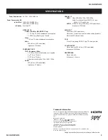
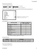
Specifi cations ................................................................................. 4
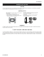
Warnings and Cautions .................................................................. 6
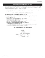
Safety-Related Component Warning .............................................. 7
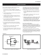
Safety Check-Out ........................................................................... 9
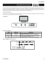
Self-Diagnostic Function ............................................................... 10
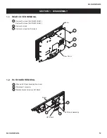
SECTION 1: DISASSEMBLY ............................................................... 12
1-1. Rear Cover Removal ............................................................ 12
1-2. HL1 Board Removal
............................................................. 12
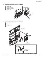
1-3. UM Board and Jack Holder Removal ................................... 13
1-4. BG2A Board and RF Bracket Removal ................................ 13
1-5. G Bracket and GM Board Removal ...................................... 14
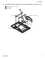
1-6. VESA Arms, Under Cover and Table-Top Stand Removal
(KLV-32L400A ONLY) .......................................................... 15
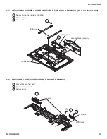
1-7. VESA Arms, Under Cover and Table-Top Stand Removal
(KLV-32L400A ONLY) .......................................................... 16
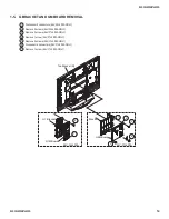
1-8. Speaker, Light Guide and HL5 Board Removal ................... 16
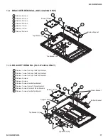
1-9. Brackets Removal (KLV-32L400A ONLY) ............................ 17
1-10. Bracket Removal (KLV-37L400A ONLY) .............................. 17
1-11. LCD Panel Removal ............................................................. 18
1-12. Inverter Board Removal ...................................................... 18
SECTION 2: SERVICE ADJUSTMENTS ............................................. 19
2-1. Using the Remote Commander for Electrical Adjustments .. 19
2-2. Accessing Service Adjustment Mode ................................... 19
2-3. Viewing the Service Menus .................................................. 19
2-4. Changing Service Data ........................................................ 20
2-4-1. Exiting Service Mode ................................................. 20
2-5. Verifying Service Data Changes .......................................... 20
SECTION 3: DIAGRAMS ..................................................................... 21
3-1. Circuit Boards Location ........................................................ 21
3-2. Printed Wiring Boards and
Schematic
Diagrams
Information
......................................... 21
3-3. Block Diagram
...................................................................... 23
3-4. Schematics and Supporting Information .............................. 24
BG2A Board Schematic Diagram (1 of 8) ............................ 24
BG2A Board Schematic Diagram (2 of 8) ............................ 25
BG2A Board Schematic Diagram (3 of 8) ............................ 26
BG2A Board Schematic Diagram (4 of 8) ............................ 27
BG2A Board Schematic Diagram (5 of 8) ............................ 28
BG2A Board Schematic Diagram (6 of 8) ............................ 29
BG2A Board Schematic Diagram (7 of 8) ............................ 30
BG2A Board Schematic Diagram (8 of 8) ............................ 31
G1M Board Schematic Diagram (KLV-32L400A ONLY) ....... 34
G5M Board Schematic Diagram (KLV-37L400A ONLY) ....... 37
HL1 Board Schematic Diagram ............................................ 40
HL5 Board Schematic Diagram ............................................ 42
UM Board Schematic Diagram ............................................. 44
3-5. Semiconductors ................................................................... 46
SECTION 4: EXPLODED VIEWS ........................................................ 47
4-1. Rear Cover Assembly and Table-Top Stand Assembly ....... 47
4-2. Chassis ................................................................................ 48
4-3. Connectors (KLV-32L400A Only) ......................................... 49
4-4. Connectors (KLV-37L400A Only) ......................................... 50
4-5. Bezel Assembly and LCD Panel (KLV-32L400A Only) ......... 51
4-6. Bezel Assembly and LCD Panel (KLV-37L400A Only) ......... 52
4-7. Screw Legend ...................................................................... 53
SECTION 5: ELECTRICAL PARTS LIST ............................................ 54
APPENDIX A: ENCRYPTION KEY COMPONENTS ..........................A-1


