background image

27

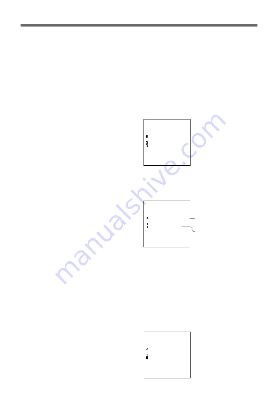
M A N U A L   A D J U S T

L o a d : F a c t o r y D a t a

( W h i t e )

L u m i n a n c e : 0 7 F
B r i g h t n e s s : 0 7

U N I T   T Y P E : L D U - 3 0

• Load: Factory Data (White) [D]: Displays white by reading the

factory preset B, R and G data

• Load: Factory Data (Blue)

*

: Displays blue by reading the factory

preset B, R and G data

• Load: Factory Data (Red)

*

: Displays red by reading the factory preset

B, R and G data

• Load: Factory Data (Green)

*

: Displays green by reading the factory

preset B, R and G data

• Save: [E]: Stores the currently displayed revised data in the memory

* Even when you select “Load: Factory Data (Blue)”, “(Red)” or “(Green)” mode, the

display unit always reads B, R and G data. If you save the data after displaying any
color, B, R and G data will return to the factory preset data. You cannot save single
color data.

If necessary, you can set the luminance and brightness of the whole unit to
the level at which you can easily make adjustment. If this is not required,
skip steps 3 to 5 below.

3

Press the SETUP button.

Adjustment can be made only in unit.

4

To change the luminance or brightness of the whole unit, select
“Luminance” or “Brightness” with the 

 or 

 button, then change the

data with the 

 or 

ı

 button, or the numeric buttons.

The adjustable range is 256 levels from 000 to 0FF for luminance, and
16 levels from 00 to 0F for brightness.
The level increases by 1 when you press the 

 button and decreases by

1 when you press the 

ı

 button. You can also select the level by

pressing the numeric buttons that correspond to its level (for example,
to set it to 07F, press 0, 7 then F).

Example: Setting the brightness to 0A

Mode

Luminance

Brightness

(Continued)

A D J U S T   S e t   U p

L o a d : F a c t o r y D a t a

( W h i t e )

L u m i n a n c e : 0 7 F
B r i g h t n e s s : 0 7

U N I T   T Y P E : L D U - 3 0

A D J U S T   S e t   U p

L o a d : F a c t o r y D a t a

( W h i t e )

L u m i n a n c e : 0 7 F
B r i g h t n e s s :   O A

U N I T   T Y P E : L D U - 3 0

Summary of Contents for JumboTron

Page 1: ...JumboTron Unit Alignment Controller 3 864 807 13 1 JME UA200 Operating Instructions Before operating the unit please read this manual thoroughly and retain it for future reference 1998 by Sony Corporation ...

Page 2: ...ipment For the customers in Europe This product with the CE marking complies with both the EMC Directive 89 336 EEC and the Low Voltage Directive 73 23 EEC issued by the Commission of the European Community Compliance with these directives implies conformity to the following European standards EN60950 Product Safety EN55103 1 Electromagnetic Interference Emission EN55103 2 Electromagnetic Suscepti...

Page 3: ...Only 29 When Using the Unit Alignment Sensor JME US35C JME US1515 or JME US1540 30 When Using the Unit Alignment Sensor JME US30L 36 Checking the JumboTron Display Unit Functions 44 Selecting the check mode 44 Resetting the microprocessor in a JumboTron display unit to its initial condition UNIT Reset 46 Checking the operation of the indicator on the rear of a JumboTron display unit LED Check 46 C...

Page 4: ...ny heavy object on it If the power cord has been damaged a fire or electric shock hazard may occur To disconnect the power cord pull it out by the plug Never pull the cord itself Do not use a damaged power cord Do not drop any liquid or solid object into the cabinet On cleaning Clean the case and front panel with a dry soft cloth or a soft cloth slightly moistened with a mild detergent solution Do...

Page 5: ...less of whether it is day or night indoors or outdoors Images to be displayed on the JumboTron screen The JumboTron system can display the following three types of images a Video images input from equipment such as a VCR video camera and video disc INPUT 1 b Computer graphics INPUT 2 c Mixed images of INPUT 1 and INPUT 2 INPUT 1 images are superimposed on the monochrome area of INPUT 2 images Over...

Page 6: ... cells for the CRT type and 16 cells for the LED type There are four unit types the JTU 35 series with 35 mm picture element pitch and JTU 17 series with 17 5 mm pitch of the CRT type and the LDU 15 series with 15 mm pitch and LDU 30 series with 30 mm pitch of the LED type You can configure a large JumboTron screen by arranging the JumboTron display units vertically and horizontally to suit variou...

Page 7: ...ts 144 cells 576 dots NTSC max 40 units 160 cells 640 dots PAL max 48 units 192 cells 768 dots LED type LDU 30 series RGB trio dot B R G Picture element pitch 2 dots 4 dots Cell Front panel 4 cells 8 dots 4 cells 16 dots Unit 2 panels 16 dots 2 panels 32 dots JumboTron screen NTSC max 30 units 480 dots PAL max 36 units 576 dots NTSC max 20 units 640 dots PAL max 24 units 768 dots ...

Page 8: ...ideo camera Switcher Microphone Audio amplifier Speaker system Frame synchronizer Screen site Computer JTC C200 ICU controller Monitor Modem JME UA200 unit alignment controller JumboTron screen JTA LS200 ABC sensor unit JTC P200 image control unit ICU Power source JME SA200 screen alignment controller Cellular phone Public telephone line Digital data card Audio mixer Monitor Overview of the JumboT...

Page 9: ...ight emitting element of R G and B which composes a JumboTron display unit and adjust its lumincance This allows you to obtain luminance uniformity of the whole screen Automatic luminance adjustment After measuring the data of a cell which is emitting light correctly using a unit alignment sensor not supplied you can adjust other cells automatically to the same data as the correct cell Function ch...

Page 10: ...n select and display the desired signal among eleven signals WHITE BLUE RED GREEN STAIR STEP COLOR BAR V vertical color bar COLOR BAR H horizontal color bar CHARACTERS BEAM BLANKING TEST and RASTER ADJUST button Adjusts the luminance of a JumboTron display unit UNIT CONTROL button Checks the functions of a JumboTron display unit DEMO demonstration button Used for the demonstration function 6 OPERA...

Page 11: ... be adjusted 2 COM connector D sub 9 pin Connect a computer to display the data for demonstration 3 SENSOR connector Half pitch 20 pin Connect a unit alignment sensor not supplied 4 AC IN connector Connect the AC power supply of 100 240 V Use the supplied AC power cord which fits the AC outlet in your area 1 2 3 4 ...

Page 12: ...Instructions supplied with the unit alignment sensor Connecting several JumboTron display units You can combine several units as a small screen and connect them to the controller for a simple demonstration Press the DEMO button on the controller to perform demonstration Up to 16 units can be connected Connections to 100 240 V AC JTU 35 JumboTron display unit rear JME US30L unit alignment sensor bo...

Page 13: ...gnal WHITE BLUE RED GREEN STAIR STEP COLOR BAR V COLOR BAR H CHARACTERS BEAM BLANKING TEST RASTER White signal Blue signal Red signal Green signal Uniform bit signal Vertical color bar signal Horizontal color bar signal Character signal Pattern with alternate line blanking Scrolls all the test signals Adjusts the luminance of red green and blue separately in the range of 256 levels Operations and ...

Page 14: ...G 8 CHARACTERS 7 Example Selecting COLOR BAR V by pressing or ı button or numberic button 5 5 Press the ENTER button The selected test signal is displayed on the JumboTron display unit Title menu UNIT type select menu Type of test signal Current luminance Current brightness Scroll speed Color bar width Luminance of R G and B of the cell in the upper left corner of the unit The data is displayed in...

Page 15: ...te There are some items that cannot be specified according to the test signals The cursors of these items are shown as and the levels of the data are shown as or Continued Items to be specified Luminance Brightness Scroll speed Color bar width Clock of the output signal Number of display lines S P G S e t U p S P G C O L O R B A R V B R T 0 7 S P D 0 3 L U M 0 7 F W I D 0 1 B L U E 0 7 F R E D 0 7...

Page 16: ... to 0F 1024 levels in the range from 000 to 3FF 1024 levels in the range from 000 to 3FF 1024 levels in the range from 000 to 3FF If you change the CLK setting while the JumboTron display unit is in operation the unit cannot receive the signal from this controller In this case disconnect the unit then turn on back the power of the unit If you increase the number of display lines with SPD scroll sp...

Page 17: ... 140 60 180 70 1C0 80 200 90 240 A0 280 B0 2C0 C0 300 D0 340 E0 380 F0 3C0 FF 3FF Relation between luminance and brightness BRT brightness indicates the adjustable range of the brightness for a JumboTron display unit emitted LUM luminance shows the tone with the set brightness JTU 35 JTU 17 series Brightness of a JumboTron display unit LDU 15 LDU 30 series ...

Page 18: ... 17 Adjustment mode G1V White G1V Blue G1V Red G1V Green REF VOLTAGE G1V Blue B G1V Red R G1V Green G REF VOLTAGE B REF VOLTAGE R REF VOLTAGE G Adjustment Changes the luminance level of white three colors simultaneously for each pixel in white display by changing the voltage applied to the cell Changes the luminance level of blue for each pixel in white display by changing the voltage applied to t...

Page 19: ...adjustment range of the current applied to blue red and green LEDs Changes the luminance level in blue display by changing the current applied to a blue LED Changes the luminance level in red display by changing the current applied to a red LED Changes the luminance level in green display by changing the current applied to a green LED Changes the luminance level in blue display by changing the adj...

Page 20: ... MANUAL with the or button and press the ENTER button The controller enters manual adjustment mode UNIT type select menu Title menu S O N Y J u m b o T r o n J M E U A 2 0 0 v e r X X X S e l e c t U N I T T y p e J T U 3 5 S e r i e s J T U 1 7 S e r i e s L D U 1 5 S e r i e s L D U 3 0 S e r i e s G 3 0 S e r i e s A D J U S T M E N U M A N U A L S E N S O R U N I T T Y P E J T U 3 5 Manual adj...

Page 21: ...4 G1 VOLTAGE G 8 G1 VOLTAGE R 9 G1 VOLTAGE B A PWM Green G 7 PWM Red R 6 PWM Blue B 5 JTU 17 G1V White 0 G1V Blue 1 G1V Red 2 G1V Green 3 REF VOLTAGE 4 G1V Green G 7 G1V Red R 6 G1V Blue B 5 REF VOLTAGE B 8 REF VOLTAGE R 9 REF VOLTAGE G A LDU 15 LDU 30 If White 0 If Blue 1 If Red 2 If Green 3 If Range 4 If Blue B 5 If Green G 7 If Red R 6 If Range B 8 If Range R 9 If Range G A 2 Selecting the targ...

Page 22: ...utton and decreases by 1 when you press the ı button You can also select the level by pressing the numeric buttons that correspond to its level for example to set it to 07F press 0 7 then F Example Setting the brightness to 0A 9 Press the ENTER button to finish the setting The selected target of adjustment luminance and brightness data are stored in the memory The stored data are retained even aft...

Page 23: ...d M A N U A L A D J U S T A D J P W M W H I T E T a r g e t C E L L L u m i n a n c e 0 7 F B r i g h t n e s s 0 7 H 0 1 V 0 1 U N I T T Y P E J T U 3 5 M A N U A L A D J U S T A D J P W M W H I T E T a r g e t C E L L L u m i n a n c e 0 7 F B r i g h t n e s s 0 7 H 0 4 V 0 3 U N I T T Y P E J T U 3 5 Target of adjustment UNIT CELL PIXEL UNIT CELL PIXEL UNIT CELL PIXEL UNIT CELL PIXEL Selectabl...

Page 24: ...V 03 01 H V 04 01 H V 01 02 H V 02 02 H V 03 02 H V 04 02 H V 01 03 H V 02 03 H V 03 03 H V 04 03 H V 01 04 H V 02 04 H V 03 04 H V 04 04 01 H V 02 03 04 16 16 01 03 02 04 LDU 30 H V 02 01 H V 03 01 H V 04 01 H V 05 01 H V 06 01 H V 07 01 H V 08 01 H V 01 02 H V 02 02 H V 03 02 H V 04 02 H V 05 02 H V 06 02 H V 07 02 H V 08 02 H V 01 03 H V 02 03 H V 03 03 H V 04 03 H V 05 03 H V 06 03 H V 07 03 H...

Page 25: ...ot be adjusted To adjust the luminance of another cell Press the HOLD button to cancel the HOLD mode then follow steps 10 to 13 To adjust the luminance of another pixel or in another manual adjustment mode Press the ENTER button then follow steps in procedures 3 and 4 Adjustment mode PWM White PWM Blue PWM Blue B PWM Red PWM Red R PWM Green PWM Green G G1 VOLTAGE G1 VOLTAGE B R G G1V White G1V Blu...

Page 26: ... changing the revised data Load Factory Data mode After displaying these revised data you can store them in the memory Save mode The Load Factory Data mode is available only for the following versions of the JumboTron display unit LDU 3050 with serial number 1001758 and later numbers program ROM ver 1 2 and later versions LDU G3050 with serial number 1000001 and later numbers program ROM ver 1 2 a...

Page 27: ... the whole unit to the level at which you can easily make adjustment If this is not required skip steps 3 to 5 below 3 Press the SETUP button Adjustment can be made only in unit 4 To change the luminance or brightness of the whole unit select Luminance or Brightness with the or button then change the data with the or ı button or the numeric buttons The adjustable range is 256 levels from 000 to 0F...

Page 28: ...ut 15 seconds the display returns to that in step 2 When you select Save in step 2 Press the WRITE button The displayed data are saved and the selected test signal with the SPG button appears After about 15 seconds the display returns to that in step 2 Pressing the ENTER button cancels saving and the display returns to that in step 2 To save the factory preset data Perform steps 2 to 8 to display ...

Page 29: ...res vary with the unit alignment sensor you are using For connection with the unit alignment sensor see page 12 For installing the sensor to the cell refer to the Operating Instructions of a respective sensor Adjusting the Luminance Automatically Using a Unit Alignment Sensor JTU 35 LDU 15 and LDU 30 Only POWER switch HOLD button ADJUST button ENTER button CURSOR ı buttons ...

Page 30: ...e the Operating Instructions of the JME US35C JME US1515 or JME US1540 Measuring the Correct Luminance Fit the unit alignment sensor to the cell where the correct luminance the original luminance for the adjustment is obtained then measure the luminance to store the data in the controller 1 Set the POWER switch to ON The title menu appears in the display window then display changes to the UNIT typ...

Page 31: ...o n S e l e c t L U M 3 F F F I X B R T 0 0 7 F I X H 0 1 V 0 1 U N I T T Y P E L D U 1 5 S E N S O R M E A S U R E P o s i t i o n S e l e c t L U M 3 F F F I X B R T 0 0 7 F I X H 0 4 V 0 1 U N I T T Y P E L D U 1 5 Numbering a cell position 7 Press the HOLD button The selected cell is stored in the memory and stops blinking HOLD appears in the display window JTU 35 LDU 15 H V 01 01 H V 01 02 H ...

Page 32: ...nment sensor is turned off until adjustment is made The SENSOR ADJUST menu is restored JME UA200 After measurement During measurement JumboTron display unit Unit alignment sensor S E N S O R M E A S U R E M e a s u r i n g N o w L U M 3 F F F I X B R T 0 0 7 F I X H 0 4 V 0 1 U N I T T Y P E L D U 1 5 S E N S O R M E A S U R E M e a s u r i n g E n d P U S H A n y K e y L U M 3 F F F I X B R T 0 0...

Page 33: ... the cell in the bottom right corner of the unit 3 Press the HOLD button The selected cell is stored in the memory and stops blinking HOLD appears in the display window Luminance of the unit for adjustment Brightness of the unit for adjustment Position of the cell to be adjusted S E N S O R A D J U S T P o s i t i o n S e l e c t L U M 3 F F F I X B R T 0 0 7 F I X H 0 1 V 0 1 U N I T T Y P E L D ...

Page 34: ... Judgement is displayed and the display changes to the Adjust Result menu by pressing the ENTER button When Judgement is OK Press the ENTER button once in the Adjust Result menu to restore the SENSOR ADJUST menu When Judgement is NG Check an NG dot in the Adjust Result menu then readjust it For the Adjust Result menu see page 35 After adjustment During adjustment S E N S O R A D J U S T A d j u s ...

Page 35: ...step 1 on page 33 When NG still appears adjustment failure may be caused by the light emitting limits of the cell It is recommended that you replace the cell that contains the NG dot Finishing the adjustment Select Quit from the SENSOR ADJUST menu with the or button and press the ENTER button A d j u s t R e s u l t 1 2 3 4 U N I T T Y P E L D U 1 5 C e l l H 0 4 V 0 4 B R G B R G B R G B R G 2 0 ...

Page 36: ... of the JME US30L Note WhenyouusetheJME US30LfortheLDU G3050displayunit check thatyouareusingtheprogramver 3 1 0orlaterversionsoftheunit alignmentcontroller Theversionisshowninthetitlemenu Theearlier versionsofthecontrollerdonotprovideproperadjustment Measuring the Correct Luminance Fittheunitalignmentsensortothepositionofthefrontpanelwherethe correctluminance theoriginalluminancefortheadjustment ...

Page 37: ...tomeasuretheluminance Theeightdotsinthetop leftcorneroftheselectedpositionblink Example Measuringtherighthalfofthefrontpanel S E N S O R M E A S U R E P o s i t i o n S e l e c t L U M 3 F F F I X B R T 0 0 7 F I X H R V U N I T T Y P E L D U 3 0 7 PresstheHOLDbutton Theselectedpositionisstoredinthememoryandthedotsstop blinking HOLD appearsinthedisplay S E N S O R M E A S U R E W a i t i n g S t a...

Page 38: ... w L U M 3 F F F I X B R T 0 0 7 F I X H R V U N I T T Y P E L D U 3 0 S E N S O R M E A S U R E M e a s u r i n g E n d P U S H A n y K e y L U M 3 F F F I X B R T 0 0 7 F I X H R V U N I T T Y P E L D U 3 0 Note Theunitalignmentsensorissettoadjustcellswhoseluminancehasbeen adjustedtoalowerlevelthanthefactorypresetlevel Ifyoutrytomeasure theluminanceofacellwhichisadjustedtoahigherlevelthanthefact...

Page 39: ...t is selected When Panel is selected Thedisplayshowsthefrontpanelpositionselectmenu S E N S O R A D J U S T P o s i t i o n S e l e c t L U M 3 F F F I X B R T 0 0 7 F I X H L V U N I T T Y P E L D U 3 0 1 Pressthe or ıbuttontoselectthepositionofthefrontpanel whereyouwanttoadjusttheluminance Theeightdotsinthetop leftcorneroftheselectedpositionblink Example Adjustingthelefthalfofthefrontpanel S E N...

Page 40: ...ontpanelwherethesensoris fittedisautomaticallyadjusted Thefollowingdisplayappears During adjustment After adjustment S E N S O R A D J U S T A d j u s t i n g N o w L U M 3 F F F I X B R T 0 0 7 F I X H L V U N I T T Y P E L D U 3 0 S E N S O R A D J U S T A d j u s t E N D W r i t e N o w L U M 3 F F F I X B R T 0 0 7 F I X H L V U N I T T Y P E L D U 3 0 AdjustEND appearsandtheadjusteddataisstor...

Page 41: ...ontheleft halfofthefrontpanel S E N S O R A D J U S T P o s i t i o n S e l e c t L U M 3 F F F I X B R T 0 0 7 F I X H 0 1 V 0 8 U N I T T Y P E L D U 3 0 2 PresstheHOLDbutton Theselecteddotisstoredinthememoryandstopsblinking HOLD appearsinthedisplay S E N S O R A D J U S T W a i t i n g S t a r t L U M 3 F F F I X B R T 0 0 7 F I X H 0 1 V 0 8 H O L D U N I T T Y P E L D U 3 0 3 Movetheunitalign...

Page 42: ... 1 V 0 8 U N I T T Y P E L D U 3 0 AdjustEND appearsandtheadjusteddataisstoredinthememory Then Judgement isdisplayedafterabout10seconds When Judgement is OK Press the ENTER button once to restoretheSENSORADJUSTmenu When Judgement is NG Press the ENTER button once to restoretheSENSORADJUSTmenu thenreadjusttheluminance byrepeatingfromstep1onpage39 Numbering a dot position Thetop leftdotonthefrontpan...

Page 43: ...entotheSENSORADJUSTmenu A d j u s t R e s u l t 1 2 3 4 U N I T T Y P E L D U 3 0 B R G B R G B R G B R G 2 0 0 0 0 0 0 0 0 0 0 0 0 1 0 0 0 0 0 0 0 0 0 0 0 0 3 0 0 0 0 0 0 0 0 0 0 0 0 4 0 0 0 0 0 0 0 0 0 0 0 0 PresstheENTERbuttontorestoretheSENSORADJUSTmenu and readjusttheluminanceofanNGdotbyrepeatingfromstep1onpage39 When NG stillappears checktheluminanceofanNGdotandthatofan OKdotbyeyefromadistan...

Page 44: ...oprocessor in a unit to its initial condition Checks the operation of the indicator on the rear of a unit Checks the blinking and lighting operations of a unit Checks the operation of the test signal generator built in a unit Checks the communication between the controller and a specified unit by displaying the unit type in use in the display window Displays the revised light emission data of each...

Page 45: ...nit type select menu U N I T C O N T R O L U N I T R e s e t C u r s o r C h e c k U N I T S P G L E D C h e c k U N I T T Y P E J T U 3 5 U N I T T y p e R e v i s e D a t a JTU 35 JTU 17 LDU 15 U N I T C O N T R O L U N I T R e s e t L E D C h e c k C u r s o r C h e c k U N I T T Y P E L D U 1 5 U N I T S P G U N I T T y p e R e v i s e D a t a U N I T C o n d i t i o n F a n S p e e d F a s t ...

Page 46: ...processor in a JumboTron display unit to its initial condition UNIT Reset Use this function to reset a unit by sending the reset signal to the microprocessor built in the unit The unit is reset to the normal light emitting condition Select UNIT Reset from the UNIT CONTROL menu The following display appears in the display window and after about a second the display returns to the UNIT CONTROL menu ...

Page 47: ...on to finish checking The display window returns to the UNIT CONTROL menu The indicators which are lit or blinking turn off The indicator blinks The indicator lights The indicator turns off The indicator blinks in red The indicator lights in red The indicator lights in green The indicator blinks in green U N I T C O N T R O L L E D C h e c k M e n u B l i n k O f f O n U N I T T Y P E J T U 3 5 U ...

Page 48: ...nks again The cell which does not blink is shown in white if you select W in step 2 If you select B that cell is shown in black To check if the frame of a unit lights up JTU 17 and LDU 15 only 2 Press or to select Frame W or Frame B and press the ENTER button The outmost dots around the unit light up If the SPG Mode test signal mode is set to WHITE you may not check if they light or not In this ca...

Page 49: ...u select Stair Step Color Bar or Characters not selectable for LDU 15 and LDU 30 the selected test signal scrolls When you select Free Running various test signals automatically scroll one after another 3 To stop scrolling press the button to select Stop then press the ENTER button 4 Press the UNIT CONTROL button to finish checking The display window returns to the UNIT CONTROL menu U N I T C O N ...

Page 50: ...e signal to display its unit type JTU 35 JTU 17 LDU 15 or LDU 30 in the display window Example Checking the communication with the unit No 02 3 To check other units press the ENTER button again then repeat step 2 4 Press the UNIT COTNROL button to finish checking The display window returns to the UNIT CONTROL menu If the selected unit number does not exist or the communication is not carried out c...

Page 51: ...asic clock G1V to check the revised data of voltage applied to each cell CELL Down to check for defective cells in a specified unit Ip to check the HV High Voltage current value of a specified unit Specifies the screen you want to check SCREEN No all is displayed automatically You cannot change this item Specifies the setting number of the switch on the rear of the unit to be checked 1 96 G1V to c...

Page 52: ...To check the revised light emission data of each dot The light emission data of each dot in a JumboTron display unit are adjusted to light evenly You can check the revised data of each dot in the display window In step 2 on page 51 set SCREEN No JTU 17 LDU 15 and LDU 30 only and UNIT Address then select one of the following modes JTU 35 PWM The revised pulse width data of each dot for the selected...

Page 53: ...1 F 1 F 1 F 1 F 1 F 1 F 1 F 1 F 1 F 1 F 1 F 1 F B 3 R G 1 F 1 F 1 F 1 F 1 F 1 F B 4 R G 1 F 1 F 1 F 1 F 1 F 1 F 1 F 1 F 1 F 1 F 1 F 1 F 1 F 1 F 1 F 1 F 1 F 1 F Dot number 1 4 B R G B 1 R G 1 1 F 1 F 1 F 2 1 F 3 1 F 4 1 F B 2 R G 1 F 1 F 1 F 1 F 1 F 1 F 1 F 1 F 1 F 1 F 1 F 1 F 1 F 1 F 1 F 1 F 1 F 1 F B 3 R G 1 F 1 F 1 F 1 F 1 F 1 F B 4 R G 1 F 1 F 1 F 1 F 1 F 1 F 1 F 1 F 1 F 1 F 1 F 1 F 1 F 1 F 1 F...

Page 54: ...e cells JTU 35 and JTU 17 only The JumboTron display unit checks for defective cell and shows it in the display window In step 2 on page 51 set SCREEN No JTU 17 only and UNIT Address then select CELL Down to display the data in the display window HV current value U N I T C O N T R O L C e l l D o w n S C R E E N N o A 1 1 U n i t A d d r e s s 0 1 U N I T T Y P E J T U 3 5 M O D E C e l l D o w n ...

Page 55: ...eaning Thermal OK or NG B R G Power OK or NG 3 Press the UNIT CONTROL button to finish checking If the selected unit number or screen number does not exist or the communication is not carried out correctly The Communication Error appears in the display window instead of the data Check the cause and try to repeat the steps above Checking the fan operation Checking the internal temperature of the un...

Page 56: ...lecting Slow Specifications Power requirements 100 to 240 V AC 50 60 Hz Current consumption 0 2 A Peak inrush current 1 Power ON current probe method 26 05 A 230 V 2 Hot switching inrush current measured in accordance with European standard EN55103 1 9 95 A 230 V Dimensions 200 240 90 mm 77 8 91 2 35 8 inches Mass 1 6 kg 3 lb 8 oz Operating temperature 0 C to 45 C 32 F to 113 F Operating humidity ...

Reviews: