


HXR-MC1500C/MC1500P/MC2000E/MC2000J/MC2000N/MC2000U
2-1
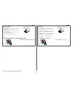
2. REPAIR PARTS LIST
Follow the disassembly in the numerical order given.
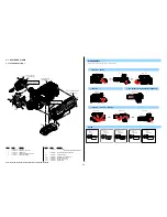
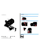
IDENTIFYING PARTS
Link
ACCESSORIES
ASSEMBLY
(ENGLISH)
NOTE:
• -XX, -X mean standardized parts, so they may have some differences from the original
one.
• Items marked “
*
” are not stocked since they are seldom required for routine service.
Some delay should be anticipated when ordering these items.
• The mechanical parts with no reference number in the exploded views are not sup-
plied.
• Due to standardization, replacements in the parts list may be different from the parts
specified in the diagrams or the components used on the set.
• CAPACITORS:
uF:
μ
F
• COILS
uH:
μ
H
• RESISTORS
All resistors are in ohms.
METAL: metal-film resistor
METAL OXIDE: Metal Oxide-film resistor
F:
nonflammable
• SEMICONDUCTORS
In each case, u:
μ
, for example:
uA...:
μ
A... , uPA... ,
μ
PA... ,
uPB...
,
μ
PB... ,
μ
PC... ,
μ
PC... ,
uPD...,
μ
PD...
(JAPANESE)
【使用上の注意】
• ここに記載されている部品は, 補修用部品であるため, 回路図及びセットに付いてい
る部品と異なる場合があります。
• -XX, -Xは標準化部品のため, セットに付いている部品と異なる場合があります。
•
*
印の部品は常備在庫しておりません。
• コンデンサの単位でuFはμFを示します。
• 抵抗の単位Ωは省略してあります。
金 被:金属被膜抵抗。
サンキン:酸化金属被膜抵抗。
• インダクタの単位でuHはμHを示します。
• 半導体の名称でuA..., uPA..., uPB..., uPC..., uPD...等はそれぞれμA..., μPA..., μPB...,
μPC..., μPD...を示します。
The components identified by mark
0
or dotted line with mark
0
are critical for
safety.
Replace only with part number specified.
Les composants identifiés par une marque
0
sont critiques pour la sécurité.
Ne les remplacer que par une pièce portant
le numéro spécifié.
• Color Indication of Appearance Parts
Example:
(SILVER) : Cabinet’s Color
(Silver) : Parts Color
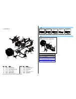
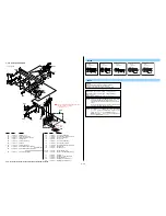
qj
MS-452 Board
2
Grip Belt Bracket (F)
4
Shoulder Pad Assy
qf
Handle Plate (A)
qd
Handle Plate (C)
qs
Handle Assy
6
Frame (R)
3
Grip Base
5
Cabinet (R) Section
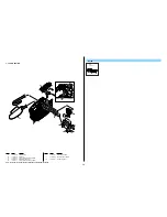
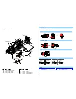
[Disassembly]
[Exploded View]
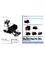
• MO-028 Board
• SP-053 Board
qh
VC Block Section
[Disassembly]
[Exploded View]
• IF-171 Board
• MM-097 Board
• US-017 Board
• VC-614 Board
• FP-1149 Flexible Board
• FP-1176 Flexible Board
• FP-1180 Flexible Board
• FP-1214 Flexible Board
• FP-1296 Flexible Board
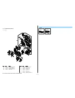
qk
Cabinet (L) Section
[Disassembly]
[Exploded View]
• JS-037 Board
• JK-398 Board
qg
Battery Panel Section
[Disassembly]
[Exploded View]
• BA-012 Board
• DC-114 Board
• HP-158 Board
q;
Handle Cover Assy
• FP-793 Flexible Board
qa
Handle Lower Cover
• MC-201 Board
1
Grip Section
[Disassembly]
[Exploded View]
• NS-023 Board
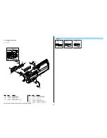
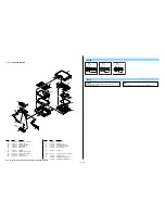
7
Lens Section
[Disassembly]
[Exploded View]
• CM-114 Board
• EC-004 Board
• LD-269 Board
• FP-1294 Flexible Board
• FP-1295 Flexible Board
9
View Finder/
LCD Panel Section
[Disassembly]
[Exploded View]
• BH-002 Board
• HI-079 Board
• RE-042 Board
• PD-427 Board
• FP-1293 Flexible Board
8
Microphone Holder
(93000) Assy
View Position
Right View
Left View
Front View
Bottom View
Top View
Back View
• Abbreviation
CH :
Chinese
model
CND :
Canadian
model
J
: Japanese model
図面番号で部品を指定するときは基板名
又はブロックを併せて指定してください。
お願い
• 外装部品色表示
例:
(SILVER) :セットの色を表す。
(Silver) :部品の色を表す。
0
印の部品,または
0
印付の点線で囲ま
れた部品は,安全性を維持するために,
重要な部品です。
従って交換時は,必ず指定の部品を使用
してください。